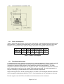
1
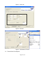
Industrial Contact Image Sensor
User’s Manual for all Versions
English version prepared by:
Gordon Scherwinsky
Page 1 of 1
CIS User’s Manual
Tichawa Vision GmbH
DISCLAIMER
Please note the following important points:
• The CIS is not intended for and may not be used for life
support applications.
• CIS internal and external LED light sources should be
treated as though they fall under Laser Class 3R
• We reserve us the right to improve the product
• With the documentation you will also get a datasheet of
your CIS with specifications
• Make sure that the cooling of the CIS is adequate. You
are able to cool the CIS over a chassis connection or a
cooling system
• Only connect the camera link cable when system is
offline
For safety reasons:
• Allow only trained persons to operate the light source
• Operate the light source only with the protective window
in place
• Do not look directly into the light source
For further details, please refer to
IEC 60285-1 “Safety of Laser Products”
Page 2 of 2
CIS User’s Manual
Tichawa Vision GmbH
1.
Frequently Asked Questions...............................................................................................5
1.1 What is a CIS sensor?.....................................................................................................5
1.2 What is the difference between a CIS and a conventional line scan camera?..................5
1.3 What are the advantages of a CIS compared to a conventional line scan camera?.........5
1.4 What are the advantages of a conventional line scan camera compared to a CIS?.........5
1.5 Why can't I buy an industrial CIS at the price of a scanner? ............................................5
1.6 How do I control the exposure of a CIS ...........................................................................5
1.7 The sharper imaging of a CIS in contrast to a conventional camera may cause
interferences if periodical patterns are inspected. What can I do?.............................................5
1.8 What distance between object and sensor (= working distance) is possible? ..................5
1.9 What is the depth of field of a CIS? .................................................................................5
1.10
Which is the local resolution of a CIS? .........................................................................5
1.11
Which local resolution do I need for my application? ....................................................6
1.12
Which line rate does my application require? ...............................................................6
1.13
What kind of illumination is best for my requirement?...................................................6
1.14
Which colour of lighting is best for my application?.......................................................6
1.15
What is PRNU like (= variation of pixel counts) at constant lighting in comparison
between a CIS and a conventional line scan camera? ..............................................................6
1.16
At which Bit does a CIS operate? .................................................................................6
1.17
Is there a difference in focus of an image taken by a CIS compared to a conventional
line scan camera? .....................................................................................................................6
1.18
What is the spectral sensitivity of a CIS like?................................................................6
1.19
Is it possible to build a sensor without gaps?................................................................6
1.20
What do I have to take care of when I install a CIS?.....................................................7
1.21
Design Rules and Choice of Materials..........................................................................7
1.1.1 Software Standards and Test Methods .....................................................................7
1.1.2 Firmware Standards and Test Methods.....................................................................7
1.1.3 Choice of Materials ...................................................................................................7
1.2 Validation ........................................................................................................................7
1.2.1 Standard Products ....................................................................................................7
1.2.2 Modified Standard Products ......................................................................................7
1.2.3 Customer Specific Products ......................................................................................7
1.3 Life Expectance and Long Term Availability ....................................................................7
1.3.1 MTBF ........................................................................................................................7
1.3.2 List of Single Source Components and supplier history.............................................8
1.3.3 Supply List ................................................................................................................8
2.
Introduction to the Industrial Contact Image Sensor............................................................8
2.1 General Characteristics ...................................................................................................8
2.1.1 Description................................................................................................................8
2.1.2 Scan geometry..........................................................................................................8
2.1.3 Illumination................................................................................................................9
2.1.4 RGB Modus ..............................................................................................................9
2.1.5 Software control ........................................................................................................9
2.1.6 Regulatory compliance..............................................................................................9
2.2 Industrial CIS Models ......................................................................................................9
2.2.1 Resolution.................................................................................................................9
2.3 MiniCIS 4 Models ..........................................................................................................10
2.3.1 Resolution and Sensorhead possibilities .................................................................10
2.4 MidiCIS Models .............................................................................................................11
2.4.1 cross-section of a MidiCIS.......................................................................................12
2.5 Modular CIS ..................................................................................................................12
Page 3 of 3
2.5.1 cross-section of a modular CIS ..............................................................................13
2.5.2 Power Consumption................................................................................................13
2.5.3 Operating requirements ..........................................................................................13
2.6 Basic CIS Operation ......................................................................................................15
2.7 GRIN lens operation ......................................................................................................15
2.8 Cautions for installation .................................................................................................16
2.8.1 Electrostatic discharge ............................................................................................16
2.8.2 Window damage .....................................................................................................16
2.8.3 LED shielding..........................................................................................................16
2.8.4 Thermal control .......................................................................................................16
3.
Electrical Interfacing .........................................................................................................17
3.1 Warning.........................................................................................................................17
3.2 Connectors, cables and signals .....................................................................................17
3.2.1 Power connector Type 03221 (CIS 4, 25 dpi CIS)...................................................17
3.2.1.1 Power connector Type 00091 (MiniCIS 4) ........................................................18
3.2.1.2 Power connector Type 03974 (modular CIS, MIDICIS).....................................18
3.2.1.3 CameraLink interface........................................................................................18
3.2.1.4 Control signals..................................................................................................19
3.2.1.5 Data bus ...........................................................................................................19
3.2.1.6 Serial communication .......................................................................................20
Control commands .....................................................................................................................20
3.3 Status commands..........................................................................................................20
3.4 Scan commands............................................................................................................21
3.5 Image data commands ..................................................................................................21
3.6 Setup commands...........................................................................................................22
3.7 Calibrating the Shading Correction ................................................................................23
3.7.1 Calibrating the Shading Correction RGB .................................................................24
3.8 Difference between real pixel count and logical pixel count ...........................................25
4.
CIS handling instructions ..................................................................................................25
4.1 Electrostatic discharge ..................................................................................................25
4.2 Protecting Against Dust, Oil and Scratches ...................................................................26
4.3 Cleaning the Sensor Window ........................................................................................26
4.4 Proper Grounding of the CIS .........................................................................................26
5.
Software ...........................................................................................................................26
5.1 Tichawa Vision User interface .......................................................................................26
5.1.1 Install UI..................................................................................................................26
5.1.2 Handling of the User interface.................................................................................26
5.2 Tichawa Vision CIS configurator....................................................................................29
5.2.1 Install Configurator ..................................................................................................30
5.2.2 Handling of the Configurator ...................................................................................30
5.3 Short introduce for Camexpert (Dalsa Grabber) Software and Camera File...................32
6.
Troubleshooting................................................................................................................32
6.1 Simple problems............................................................................................................32
6.2 Troubleshooting using the serial interface .....................................................................32
6.3 Optical tests...................................................................................................................33
6.4 Safety Matrix .................................................................................................................33
Page 4 of 4
1. Frequently Asked Questions
1.1 What is a CIS sensor?
A CIS is a compact line scan camera which is mounted directly to the object under inspection as
we can know it from fax scanners or document scanners. The CIS consits of a scanning line, a
SELFOC lens and a light source.
1.2
What is the difference between a CIS and a conventional line scan camera?
The sensor of a conventional line scan camera is small (10 - 50 mm length) with small pixels (5 20 µm) and reducing optics.
The sensor of a CIS is as wide as the object under inspection (up to 4 m), the optics produce
images at a 1 :1 scale.
1.3 What are the advantages of a CIS compared to a conventional line scan camera?
- Simple to mount, no big distance necessary
- Simple to adjust
- Constant picture angle over the total reading width
- No distortion by the lens
- Clearly sharper images
1.4 What are the advantages of a conventional line scan camera compared to a CIS?
- better depth of field (DOF)
- lower weight
1.5
Why can't I buy an industrial CIS at the price of a scanner?
- Better quality
- Higher line rate due to more complex electronics
- Bigger scanning distance (10 -14 mm instead of 0.3 mm) due to more complex lenses
- Robust built (solid metal housing)
1.6
How do I control the exposure of a CIS
By an internal or external light source which is controlled by a timer inside the CIS.
1.7
The sharper imaging of a CIS in contrast to a conventional camera may cause
interferences if periodical patterns are inspected. What can I do?
The option "multiple flashing" surpresses interferences as far as possible.
1.8 What distance between object and sensor (= working distance) is possible?
The modular CIS allows a working distance of 10 mm up to 30 mm (25 dpi) .
1.9 What is the depth of field of a CIS?
As a rule 0,1-16 mm depending on the application, focal length and light wave length.
25 dpi ~ 16 mm; ….; 200 dpi ~ 2 mm; 400 dpi ~ 1 mm; 600 dpi ~ 0,5 mm
; 1200 dpi ~ 0,43 mm (different lense)
1.10 Which is the local resolution of a CIS?
TiVi offers CIS units of 25 dpi (1.016 mm pixel grid) up to 2400 dpi (10.5 µm pixel grid).
Page 5 of 5
1.11 Which local resolution do I need for my application?
There is no clear answer to this question as it very much depends on the algorithmics used.
General speaking the smallest object to be recognized should at least be the size of 2 - 5 pixels.
Typical questions of interpolation such as defining the centre of mass etc. can be solved at a
much finer grid than the pixel grid.
1.12 Which line rate does my application require?
For most applications we recommend square pixels. The line rate is the result of transport speed
divided by pixel size.
For example: The pixel size of a 200 dpi sensor is 127 µm. At a feed speed of 1 m/sec the line
rate required is:
1m/sec ./. 0.000127 m = 8000 Hz = 8 kHz
The sensor should be operated at a line rate of 8 kHz.
1.13 What kind of illumination is best for my requirement?
One-sided reflective light is sufficient for flat structures (print).
Spacial structures (crinkled materials) require double-sided reflective light (in feeding direction in
front and behind the sensor).
Transparent and printed materials often require transmissive light.
Special applications (e.g. scanning of security papers) often require a combination of reflective
and transmissive light. CIS supports multiplex operation with two light sources.
1.14 Which colour of lighting is best for my application?
Red light is usually best for simple B/W applications.
1.15 What is PRNU like (= variation of pixel counts) at constant lighting in comparison
between a CIS and a conventional line scan camera?
Under ideal conditions (Ulbrichtkugel) a conventional line scan camera shows a typical PRNU of
10 %.
In real conditions the amplitude usually falls down to a half at the rim of the image area due to
the lens and the Law of Lambert.
Typical for a CIS is a PRNU of approx. 30 %, however, it can be reduced by internal correction
down to 1 - 2 %.
1.16 At which Bit does a CIS operate?
The industrial CIS internally operates at a 10 Bit resolution, after correction 8 Bit are read-out.
In scanners CIS-Elements are operated at resolutions between 12 and 16 Bit.
1.17 Is there a difference in focus of an image taken by a CIS compared to a conventional
line scan camera?
The focus of a line scan camera is mostly limited by the lens. At high line rates you have to open
the aperture almost completely. The B/W transition is usually 3 - 5 pixels.
The transition of a CIS is 1 - 2 pixels.
1.18 What is the spectral sensitivity of a CIS like?
Alike with CCD or CMOS cameras the pixels of a CIS are made of silicium and show as a typical
features their peak of spectral sensitivity in the near infra red light.
1.19 Is it possible to build a sensor without gaps?
The elements of a CIS are made of lined-up chips. At the joints there is either no interference (25
- 200 dpi) or interpolation is already effected by the CIS (1200-2400 dpi).
All in all the distortion observed with a CIS is smaller than the distortion of a lens and more easy
to correct (linear context, no polynom necessary).
Page 6 of 6
1.20 What do I have to take care of when I install a CIS?
A CIS is much closer to the object under inspection than a conventional camera. Therefore:
- There should be some protection to avoid that the objects jam up or fall off and damage the
sensor.
- You should take precautions against ESD, especially in applications with glass and fast running
synthetic fabrics as well as with all other materials which are charging statically<
- CIS sensors with internal light source are - as all other LED light sources - subject to the Laser
Protection Regulations, usual protection class III A. You have to obey the relevant regulations.
1.21 Design Rules and Choice of Materials
1.1.1
•
Software Standards and Test Methods
Software is subjected to the methods carried out at Tichawa Vision. No additional tests
or verifications will be done.
1.1.2
•
Firmware Standards and Test Methods
Firmware is subjected to the methods carried out at Tichawa Vision. No additional tests
or verifications will be done.
1.1.3
Choice of Materials
•
No limitation on the materials used.
1.2
Validation
1.2.1
•
They are subjected to the standard tests carried out at Tichawa Vision. No additional
tests or verifications will be done.
1.2.2
•
Modified Standard Products
They are subjected to the standard tests carried out at Tichawa Vision. Modifications will
be tested and documented in addition to the standard tests.
1.2.3
•
1.3
Standard Products
Customer Specific Products
They are subjected to the standard tests carried out at Tichawa Vision.
An acceptance test procedure will also be carried out.
Life Expectance and Long Term Availability
1.3.1
•
MTBF
The MTBF will not be calculated if it's no part of the contract.
.
Page 7 of 7
1.3.2
•
1.3.3
•
List of Single Source Components and supplier history
These documents will not be supplied if it's no part of the contract.
Supply List
A supply list will not be provided if it's no part of the contract.
Specification of CIS
The camera needs a power supply of 24V (min. 1A) except when otherwise noted.
System requirements:
IBM-compatible PC, more than 256MB RAM, more than 1GHz-CPU, mouse, keyboard,
CameraLink Cable, Powercable
Software requirements:
Grabber-Software
Terminal Program (like ProcommPlus or similar)
Warning: Some combinations of Hardwdare, Grabber and terminal program might be too slow to
catch up with the data rate at the serial interface ! Ask your frame grabber vendor for details !
Connections:
The camera is connected to the grabber over the CameraLink Cable.
2. Introduction to the Industrial Contact Image Sensor
The CIS is intended for the monitoring and controlling of production lines in an industrial
environment.
2.1 General Characteristics
The CIS is available in a wide variety of configurations of length, speed and illumination
arrangement combinations. Certain characteristics are shared by these various models.
2.1.1 Description
The CIS is an innovative line scan camera generally built from end-to-end stackable linear
sensor modules mounted on a rigid substrate. The GRIN array optics in the CIS allow the
distance from the object to the sensor to be very short, producing constant unity magnification.
Illumination is provided by a linear array of LEDS focused by a continuous glass cylinder lens.
These elements are mounted with the control and processing electronics in a rigged metal case
thus providing high sensitivity, easy alignment and immunity to vibration.
The fully parallel construction of the CIS provides unparalleled speed and resolution. With its
inherent parallel structure, the line rate, spatial resolution and sensitivity of the CIS are constant
for all scanner lengths.
2.1.2 Scan geometry
• Contact – 0 mm working distance: This option is most suitable for textile materials,
including non-wovens. While a textile production environment typically is very dusty, the
textile material moving directly across the MiniCIS 4 window can keep the window clean.
This option is suitable for materials
• Non-Contact – 8 to 14 mm working distance:
that may not come into close contact with the glass window because either the window
Page 8 of 8
itself (e.g. with sheet metal) or the material under test (e.g. paper) might be damaged or
because the object under test is not flat.
2.1.3 Illumination
• Single sided or dual sided internal LED lighting is provided, either a single color or a
mixture of colors with several different wavelengths.
• Equivalent external LED sources under CIS control are available for backlighting.
• Single-piece cylinder lenses provide high uniformity and variable focal distance. Special
shaped lenses may be used for even higher light output
2.1.4
RGB Modus
We are able to build all CIS Versions in color. For this we use a monochrom standard
Sensor with a LED RGB light source. We flash the different LEDs red, green and blue.
Over the firmware and the electronic we give a full RGB image over the CameraLink
connector out.
2.1.5
Software control
•
•
•
•
A simple ASCII protocol controls parameters such as line rate, exposure, trigger mode
and flat-field correction.
All controls are handled through the CameraLink embedded serial port.
Every code line ends with char(13).
The pixelcorrection includes more than one layer and needs also “ENTER” between the
layers
2.1.6 Regulatory compliance
• IEC 60204-1 Electrical equipment of machines – Part 1: General requirements
• IEC 60285-1 Safety of Laser Products
• EN 61010-1 Safety requirements for electrical equipment for measurement, control, and
laboratory use - Part 1: General requirements
• EN 61326 Electrical Equipment for measurement, control and laboratory use – EMC
requirements
• EN 61000 Electromagnetic compatibility (EMC)
2.2
Industrial CIS Models
All CIS scanners are built up from linear image sensor dies typically 8 mm long. These dies are
mounted onto a substrate using COB (chip on board technology) for accurate and stable
alignment and minimal inter-die gaps with additional electronics to produce an imaging module.
The modules with an active length of approx. 260 mm are rigidly connected and attached to a
metal base to produce overall scanners with active lengths of up to 4160 mm.
2.2.1 Resolution
Table 1-2 shows the available configurations and the resulting pixel totals.
CIS 4
Modules
2
4
Active
Length
(mm)
520
1040
Total Pixel Count
200
dpi
4096
8192
300 dpi
400 dpi
600 dpi
6144
12288
8192
16384
12288
24576
Page 9 of 9
6
8
10
12
14
1560
2080
2600
3120
3640
12288
16384
20480
24576
28672
18423
24576
30720
36864
43008
24576
32768
40960
49152
57344
36864
49152
61440
73728
86016
Table 1 - Pixel Count vs. Scanner length
CIS 25 dpi
Modules
1
2
3
4
5
6
7
8
Active
Length
(mm)
520
1040
1560
2080
2600
3120
3640
4160
Total Pixel
Count
25 dpi
512
1024
1536
2048
2560
3072
3584
4069
Table 2 - Pixel Count vs. Scanner length
2.3 MiniCIS 4 Models
All MiniCIS 4 scanners are built up from linear image sensor dies approximately 8 mm long.
These dies are mounted directly on a substrate (chip on board technology) for accurate and
stable alignment and minimal inter-die gaps with additional electronics to produce an imaging
module. The MINICIS4 modules have an active length of 57 mm minimum to 307 mm maximum.
•
•
•
•
•
•
•
•
•
Flat Line Scan Camera
Scan width 57, 89, 104, 216 or 307 mm
Line rates up to 12 kHz
100, 200, 300, 400 or 600 dpi corresponding to approx. 4, 8, 12, 16 or 24 dots per mm
up to 5376 Pixels
Optional Shading Correction
Camera Link Interface
Built-in Light Source & Optics
Interface Cable for Multihead Version has a length up to 5 Mtr.
2.3.1 Resolution and Sensorhead possibilities
Table 1 shows the available configurations and the resulting pixel totals.
Table 2 shows the available configurations of possible sensorheads, length and line frequency.
Modules
1
Active
Length
(mm)
89
Total Pixel Count
200 dpi
400 dpi
600 dpi
704
1408
-
Page 10 of 10
1
1
1
104
216
307
832
1728
2432
1664
3456
-
2496
5376
-
Table 1 - Pixel Count vs. Scanner length
Resolution Taps LF 307
Sensor
mm
LF 216
mm
LF 104
mm
LF 89
mm
200 dpi
2,8 kHz
11,2 kHz
1,9 kHz
3,9 kHz
1,4 kHz
5,6 kHz
2 kHz
3,7 kHz
6 kHz
4 kHz
3 kHz
6 kHz
2 kHz
-
7,1 kHz
3,8 kHz
3,5 kHz
-
300 dpi
400 dpi
600 dpi
1
4
1
2
1
2
4
1
4
2 kHz
-
LF 57mm Max.
possible
Sensorheads
8
2
8
4
8
5,5 kHz
4
2
8
3,4 kHz
2
-
Table 2 – Sensorheads
2.4
MidiCIS Models
•
•
•
•
•
•
•
•
•
•
Flat Line Scan Camera
Scan width 130, 260, 390, 520
Line rates up to 40 kHz
100, 200, 300, 400,600,900,1200,2400 dpi corresponding to approx. 4, 8, 12, 16, 24, 36,
48, 96 dots per mm
up to 49536 Pixels
Integrated Shading Correction
Camera Link Interface
Built-in Light Source & Optics
Interface Cable for Multihead Version has a length up to 5 Mtr.
RGB or Monochrom
Page 11 of 11
2.4.1
2.5
cross-section of a MidiCIS
Modular CIS
•
•
•
•
•
•
•
•
•
•
Flat Line Scan Camera
Scan width 130, 260, 390, 520
Line rates up to 40 kHz
25,100, 200, 300, 400,600,900,1200,2400 dpi corresponding to approx. 1,4, 8, 12, 16,
24, 36, 48, 96 dots per mm
up to 49536 Pixels
Integrated Shading Correction
Camera Link Interface
Built-in Light Source & Optics
Interface Cable for Multihead Version has a length up to 10 Mtr.
RGB or Monochrom
Page 12 of 12
2.5.1
cross-section of a modular CIS
2.5.2 Power Consumption
Table 1 shows the typical power consumption of the sensor array and associated electronics and
the illuminators. These are calculated using a 16 KHz scan rate. Changing the scan rate (and,
therefore, the illumination duty cycle) will change the power consumption of the illuminator.
Length
(mm)
Sensor (W)
Light (W)
520
1040
1560
2080
2600
3120
14
17
28
34
42
51
56
68
70
85
84
102
Table 1 - Power consumption
2.5.3 Operating requirements
All models require careful attention to heat sinking. Although operation in free air is safe, the CIS
should be firmly mounted to a heat conduction surface to maximize heat transfer from the
illuminator to maximize LED life and to avoid heating the sensors unnecessarily. The case
temperature should be maintained in the range of 0 to 40C. At temperatures below the local dew
point, condensation can form on the window, both inside and outside. At such temperatures, it
may be necessary to provide heated air to raise the window temperature.
When mounting the CIS, use all mounting holes in the base. Use the largest diameter bolts that
will fit through the holes (generally M4 or 3/16”). Use lockwashers or the equivalent on the nuts.
Provide support near the CIS for all cables to minimize stress on the connectors.
Page 13 of 13
The permissible storage temperature range is -10 to 60C. Bring the scanner to within the
operating temperature limits before applying power.
Resistance to shock and vibration complies with EN 61010-1. Windows and glass rods must be
taken out to comply !
The CIS is not sealed. Keep moisture and liquids away from all areas.
Page 14 of 14
2.6 Basic CIS Operation
Correct operation of CIS depends on an understanding of the basic arrangement of the
components. These are shown in Figure 1.
Figure 1 - CIS component layout
Illumination is provided by a row of LEDs and focused on the object to be viewed by a cylindrical
glass rod. Light reflected from the object is focused on a row of silicon detectors by a solid array
graded index (GRIN) rod lenses. The distance from the object to the input face of the GRIN
lenses is equal to the distance from the output face to the sensor surface. The operating
distance – from the outside of the window to the surface of the object – can be in the range of 0
to 14 mm and is preset at the factory. The depth of field is approximately 20% of the distance
from the window to the object plane and centered on the object plane.
For transmissive objects, the internal light source may be omitted and replaced by a source
behind the object. In special situations, both front and back sources may be used. A second
front source may be added to the other side of the sensor for symmetrical front illumination.
2.7 GRIN lens operation
GRIN lenses are a stacked array of glass rods each having an index of refraction that increases
from the center to the outside. This index profile causes light rays entering a GRIN at an angle to
be bent back towards the center of the rod. As a result, the GRIN acts as a lens that will focus
rays originating at a specific distance from the input face on to a plane the same distance from
the output face. Rays originating closer or farther away than the focal distance will not be
sharply focused. Because the operation of GRIN lenses is symmetric, the magnification is
always exactly 1.
A single GRIN will make an image with a size defined by its acceptance cone. To make
extended images, rows of rods are placed side by side so their cones overlap. For continuous
Page 15 of 15
coverage, two or more rows of grins in a hexagonal array are used. For stability, the rods are
surrounded by glass plates and glued into place. Figure 2 shows the construction.
Figure 2 - GRIN lens construction
2.8 Cautions for installation
Because the CIS operates close to the object under inspection certain precautions must be taken
to minimize the chance for damage.
2.8.1 Electrostatic discharge
The CIS may be damaged by the high electrostatic charges generated by moving rubber,
plastic or similar materials. Please make sure that the case is properly grounded using
several short connections of sufficient diameter. Keep connections between the CIS case
and electronics ground as short as possible (1 meter or less). Long ground lines in
conjunction with high energy might damage the device!
2.8.2 Window damage
The CIS can be damaged by materials falling directly onto the window. Please make sure
that the CIS is not subject to impacts from parts falling onto the window or to stress by
parts being pressed against the window or its frame by a transport system.
2.8.3 LED shielding
Assure that the LED illuminator or reflections from the illuminator cannot be viewed
directly when the scanner is in its operating position.
2.8.4 Thermal control
Mount the scanner firmly on a plate that conducts heat away efficiently to maintain the
enclosure temperature within the specified temperature range.
Page 16 of 16
3. Electrical Interfacing
Before attempting to operate the CIS in an industrial setting, all equipment should be interfaced
and tested for compatibility and proper operation. Testing should include operation ant the
required production speeds using the desired synchronization methods and hardware.
3.1 Warning
CameraLink components may be severely damaged by electrostatic discharge! Before
connecting the sensor CameraLink port make sure that
•
•
•
All equipment is disconnected from mains supply
Sensor ground and data processing equipment ground are connected
Standard ESD protection is provided
3.2 Connectors, cables and signals
The CIS may have up to four types of external connectors for power, CameraLink, external
illuminators and optional external rotary encoder. These are illustrated in figure 3.
+24 VDC
and
Ground
rotary
encoder
Ext.Light
Control
Camera Link 1
(Master)
3.2.1
Camera Link 2
(Slave)
Camera Link n
(Slave)
Power connector Type 03221 (CIS 4, 25 dpi CIS)
WARNING: It is extremely important that only the correct voltages be applied to your
scanner. Incorrect or reversed voltages will damage the scanner.
The power connector is located on the end of the scanner corresponding to the last pixel read
out. The pinout is shown in Table 3 and the connector is shown in Figure 4.
Pin
Signal
1
+24V
2
+24V
3
Reserved
4
Reserved
5
Return(gnd)
6
Return(gnd)
Table 3 - Power connector pinout
Figure 4 - Power
The pin configuration is MIL-C-5015 14S-6.
The mating connector for the power connector is an Amphenol type GTx06yyy-14S, where y
indicates the type of wire connection required and yyy indicates the type of cable strain relief
required. See the Amphenol GT series catalog 12-024 for details and drawings.
Page 17 of 17
3.2.1.1 Power connector Type 00091 (MiniCIS 4)
Pin
Signal
1
2
3
4
5
6
+24V
+24V
Prog
nc
Return(gnd)
Return(gnd)
Cable
color
white
yellow
green
brown
Figure 5 - Power
The power consumption has a maximum of
1,5 A and the regulation of the DC voltage
supply should be ± 1 V.
The mating connector for the power
connector is a hirose 6 pin.
Table 4 - Power connector pinout
3.2.1.2 Power connector Type 03974 (modular CIS, MIDICIS)
Pin
Signal
Cable
A1
A2
A3
A4
+24V
+24V (LED)
shield
Return(gnd LED)
1
2
yellow
3
A5
Return(gnd)
4
Figure 6 - Power
PIN A1 is the right PIN
Table 5 - Power connector pinout
The mating connector for the power connector is a SUBD 5 pin.
3.2.1.3 CameraLink interface
The CIS uses high-density 26-pin MDR26 connectors for CameraLink control signals, data
signals, and serial communications. The pinout and functions correspond to the requirements of
the CameraLink specification. Any standard
CameraLink cable up to 10 meters may be used.
Page 18 of 18
3.2.1.4 Control signals
Camera Link provides four camera control signals, CC1 through CC4, that can be defined by the
camera manufacturer. When the CIS is in the triggered mode, these signals are used for
triggering and optionally for illumination exposure control. In standard configuration exposure
control is generated by the internal CPU according to the software commands. Figure 5 shows
the timing considerations.
Strobe
CC1
Line Valid
Data
LED Light
Figure 5 - Trigger timing
The rising edge of the CC1 signal initiates scan of a line and exposure time. The wait time
between lines should be taken between the end of the Line Valid signal and the initiation of the
exposure.
The CIS allows use of up to four independent light sources and four partitions of the sensors.
Generally, the sensors are partitioned only in RGB scanners. In all other cases, the CC1 signals
control the exposure but the triggering is initiated only by CC1. Only CC1 is used in single-color
monochrome scanners.
When the CIS is not in the triggered mode, all line initiation and exposure timing is generated by
the internal CPU according to the software commands.
WARNING: Do not exceed 100 kHz repetition rate with any CC1 signal. Frequencies
higher than 100 kHz can damage the scanner.
3.2.1.5 Data bus
CIS uses one or more Camera Link Base configuration connectors in the 8-bit mode. Ports A
and B are used for data transmission with each channel carrying one-half of the scan data. Do
not use Port C. It may contain test data that will corrupt the image files.
Page 19 of 19
3.2.1.6 Serial communication
All software commands are sent via the internal Camera Link serial port. The port should be set
for the standard parameters: 9600 Baud, no handshake, no parity, 1 start bit, 8 data bits, 1 stop
bit.
Control commands
The serial interface uses a set of simple ASCII commands to configure and operate the CIS.
The following rules always apply to commands sent and received:
•
•
•
•
•
•
A carriage return <CR> ends each command. The linefeed character is ignored.
All values are assumed to be in decimal.
The commands consist of a single-character command and parameters.
The camera will answer each command with either "<Ready>", "<Error x: Error
Message>" or “<Unknown Command >”.
The ">" followed by a Carriage return <CR> are always the last characters returned
by the camera.
Values to be sent are shown as [value]. Do not send the square bracket characters.
3.3 Status commands
On power up, the CIS will execute its startup sequence by initializing all hardware, performing a
memory test, reporting any errors, and by restoring saved parameter settings and correction
coefficients. The CIS will report a list of available commands after the startup sequence has been
completed. Information on the status and configuration may be requested at any time using the
commands in Table 3. All commands are case-sensitive.
Command
List available
commands
Show software version
Show current
parameters
Save current
parameters
Get Temperature
Get Replace-Flags
Get channel to pix.
Get pixels to chan.
Get analog Gain
Get analog Offset
Get Chan. Stat.
Get Sensor Character.
Syntax
Effect
? <CR>
Displays command list
v<CR>
Displays software version
#<CR>
Lists current settings
S<CR>
Saves current settings
t<CR>
r<CR>
j[Channel]<CR>
i[Channel]<CR>
g<CR>
o<CR>
c<CR>
+<CR>
Gets the temperature inside the
CIS
Shows the Replace-Flags
Displays channel to pixel numeric
Displays pixel to channel numeric
Displays gain level
Displays offset level
Displays channel statistic
Displays Sensor Specification
Table 2 - Status command list
Page 20 of 20
3.4 Scan commands
Scan commands select the operating mode and set scan timing in the free running (not
triggered) mode. Table 4 shows the scan control commands.
Command
Set trigger mode
Line Frequency (free
running mode)
Exposure time
Light on/off
Syntax
M[mode]<CR>
F[freq]<CR>
Value
mode = 0
mode = 1
mode = 2
(optional)
mode = 3
(reserved)
mode = 4
(optional)
mode = 5
(optional)
mode = 6
(optional)
Effect
Free running / LED
Triggered by CC1 / LED
Triggered by external /
LED
reserved
Free running / neon lamp
freq = 100 …
Channel = 0,1,2,3
exp = 0 …65535
E[Color],
exp<CR>
L1<CR>=Light on
L0<CR>=Light off
L[value]<CR>
Triggered by CC1 / neon
lamp
Triggered by external /
neon lamp
Sets line frequency in free
running mode to freq in Hz
(see note 1)
Sets exposure time for
Color x
Sets exposure time in µs
(see note 2)
Turns the light on or off
Table 3 - Scan command list
Note 1: If the requested frequency has a shorter period than the exposure time in any channel,
the command is ignored and an error message is returned.
Note 2: If the requested exposure time is longer than the period set by F in channel x, the
command is ignored and an error message is returned.
3.5 Image data commands
The CIS includes capabilities for correcting darkfield and brightfield non-uniformities, for setting
output levels, and for collecting image data statistics. The commands controlling these functions
are shown in Table 5.
For enabling and disabling the correction see Table 7.
Command
Set Darkfield level
(analog/digital)
Set Brightfield level
(analog/digital)
Initiate correction
Syntax
Value
D[value],[value]<CR>
value = 0 … 64
B[value],[value]<CR>
value = 0 … 255
Sets the brightfield
level to [value]
C[value]<CR>
value = 0
other values for
test purposes
only
Initiates correction
calculations
Page 21 of 21
Effect
Sets the darkfield level
to [value]
value = 0
Clear / restore
correction data
Z[value]<CR>
value = 1
value = 2
Store correction data
$<CR>
None
Show statistics
s<CR>
None
Set Cycles
Q[value]<CR>
value=1 … 255
Clear correction data
but do not clear RPLC
flags
Load correction data
from Flash
Clear correction data
and RPLC flags
Stores current
correction data in nonvolatile memory
Displays current
sensor statistics e.g.
maxmimum Pixel,
resolution,Mode..
Number of lines used
for offset and
pixelcorrection
Automated
Offsetcalibration from
startchannel to
stopchannel
Autoset offset
I[startCH],[stopCH]<CR> Channel=0…xx
Set analog Gain
G[channel],[value]<CR>
value=0 … 63
255= all channels
Set analog Offset
O[channel],[value]<CR>
value= - 255 /
+255
255= all channels
Col=
Pixel=
Displays pixel
minimum and maxium
value
Pixelstatistics
p[col],[pixel]<CR>
Table 4 - Image data command list
3.6
Setup commands
The commands in table 6 assist in setting up systems using the CIS 4.
Command
Set video mode
Reboot
Syntax
V[mode]<CR>
!<CR>
Value (see note
1)
mode = 0 / 1
mode = 2 / 3
mode = 4 / 5
mode = 6 / 7
Effect
mode = 8 / 9
Displays live video
Displays constant zero
Displays constant 80h
Displays sawtooth test
pattern
Displays 2D test pattern
None
Reboots the CIS CPU
Table 5 setup command list
NOTE 1: Even values enable the flat field correction, odd values disable the flat field correction.
The other commands should not be used since they are not meant for the use of the CIS.
Commands and diagnostic data, which are not specified, serve the producer for diagnostic
use. They are not documented and subject to change.
Page 22 of 22
Setting the Camera Up
Step by step instructions to run the Camera
- Connect the power cable with the camera and the power supply
- Open your grabber program and the camera file for your camera
- Open your terminal software and check the following parameters:
COM PORT of your cameralink connection ( e.g. COM3)
Baud rate 9600 baud
no parity
1 start bit
8 data bits
2 stop bits
- Apply your test pattern on the camera keeping to the proper image distance
(e. g. 10 mm) showed at the label of the camera
- Turn light on (internal camera light or external light)
- Grab an image (e. g. left click on the read-in-symbol)
3.7
Calibrating the Shading Correction
Set camera up as stated above
set the digital dark level to a value close to zero, e. g. around 8..20 counts
set the digital bright level to a value close to full scale, e. g. 230 counts
grab images with a white reference object such as a sheet of white paper
clear old correction values using the “Z0” command
modify operating conditions (line rate, exposure, light level) to achieve pixel values
between 50% and 100% of the digital bright value. (The correction mechanism typically
employs a digital gain of 1..2 with starting value 1)
start a shading correction calibration cycle using the “C0” command
PHASE 1
Measuring the pixel dark values
The CIS will ask you to switch off the light and will turn off its internal light
source(s). Please avoid any stray light since it will deteriorate the results.
After all lights are OFF, then press any key to continue. The CIS will
average over the number of lines specified using the “Q” command and
save the results.
PHASE 2
Measuring the pixel bright values
The CIS will ask you to turn the light on and will turn on its internal light
source(s). After all lights are ON, then press any key to continue. The CIS
will average over the number of lines specified using the “Q” command and
save the results.
PHASE 3
Calculation and Storage
The CIS will calculate and load offset and gain correction values for each
single pixel. When you are satisfied with the result, you can store the pixel
correction values permanently using the “$” command.
NOTE 2
Statistic Data will be grabbed after the pixel correction and therefore
Page 23 of 23
submitted by the correction values.
3.7.1
Calibrating the Shading Correction RGB
The diffrence to the monochrom correction is, that 3 lines(RGB) has to be in range(3.7).
Not only one line.
Sensorboard 200dpi
Sensor Chip #1
(Pixel 1-64)
Sensor Chip #27
(Pixel 1664-1728)
Camera Link Data
Port A
Pixel 1
Pixel 1728
Sensor #1
Port B
Pixel 1
Sensor #3
Pixel 1
Pixel 1728
Sensor #2
Pixel 1728
Pixel 1
Sensor #4
Page 24 of 24
Pixel 1728
3.8
Difference between real pixel count and logical pixel count
•
•
real pixel are actually available and useable
logical pixel are available but not useable
If you have an odd count of sensors, which are transferred, over more than 1 CamerLink port you
will automatic generate virtual "dummy pixels".
(e.g. MiniCIS A4)
27 Sensors + 1 Dummy Sensor
Sensor 1
Tap 1
Sensor 1-7
Tap 2
Sensor 8-14
Tap 3
Sensor 15-21
Tap 3
Sensor 22-28
Virtual "dummy
Sensor"
13 Sensors
14 Sensors
middle
+
1 Dummy
Sensor/ Pixel
Port A
Port B
CameraLink
Port
14 Sensors + 13
Sensors + 1 dummy
Sensor = 28
Sensors
o
real pixel + dummy pixel = logical pixel
4. CIS handling instructions
Although the CIS is housed in a rugged aluminum enclosure, certain precautions are necessary
to prevent damage to the electronics and to the window.
4.1 Electrostatic discharge
The CIS sensor contains optical sensors and high-bandwidth electronics susceptible to
electrostatic discharge. Please treat the sensor and its CameraLink ports according to standard
ESD guidelines such as:
•
•
Avoid static charge buildup
Always ground the sensor and related equipment before electrical connection
Special care is required in environments like transport of webs, foils and paper where buildup of
very high electrostatic charges routinely occurs. Be sure the CIS is grounded using short copper
braid (<500 mm) before starting the material transport.
Page 25 of 25
4.2 Protecting Against Dust, Oil and Scratches
The CIS window is part of the optical path and should be handled like other optical components,
with extreme care. Dust can obscure one or more pixels, producing dark patches on the sensor
response. Dust is most visible when the illumination is collimated or when the focus is set near
the surface of the glass. The dark patches from dust on the glass will shift position as the angle
of illumination changes. Dust is normally not visible with diffuse illumination if the focus is far from
the window. Dust can normally be removed by blowing the window surface using an oil free
compressed air blower, unless the dust particles are being held by an electrostatic charge, in
which case either an ionized air blower or wet cleaning is necessary.
Oil is usually introduced during handling. Touching the surface of the window barehanded will
leave oily residues. Using rubber fingercots and rubber gloves can prevent oil contamination.
However, the friction between the rubber and the window may produce electrostatic charge that
may damage the sensor. To avoid ESD damage and to avoid introducing oily residues, ground
the CIS enclosure when cleaning the window.
Scratches on the window can be caused by improper handling, cleaning or storage of the CIS.
Tools should never come in contact with the window surface. The CIS should be stored only in
containers where it is not properly secured to prevent contact between the window and the
container. Scratches diffract incident illumination. When exposed to uniform illumination, a
sensor with a scratched window will normally have brighter pixels adjacent to darker pixels. The
location of these pixels changes with the angle of illumination.
4.3 Cleaning the Sensor Window
Use compressed air to blow off loose particles. This step alone is usually sufficient to clean the
sensor window.
If further cleaning is required, use lens cleaning paper moistened with alcohol or acetone.
Lint-free ESD-safe cloth wipers that do not contain particles that can scratch the window may
also be used.
Whatever the technique used, always wipe the window carefully and slowly.
4.4 Proper Grounding of the CIS
The CIS is grounded via the Camera Link Cable Shield. Be sure that the Data Processing
Equipment at the other end of the Camera Link Cable is properly grounded, especially in
applications with zero working distance, where the material under inspection might build up very
high electrical charges and feed them directly to the CIS. When grounding the CIS, please keep
in mind to keep it isolated from machine ground to avoid ground loops!
5. Software
5.1
Tichawa Vision User interface
5.1.1
Install UI
It gives 2 options to install the UI :
a) execute setup.exe and follow the instructions of the menu
b) unpack the TIVICISIF.zip in one folder
5.1.2
Handling of the User interface
a) execute TIVICISIF.exe
b) go to the menu options [1] (figure 1)
Page 26 of 26
c) now are 2 options available
I. serial communication over an COM port [2] (figure 2)
II.
serial communication over the grabber dll file [3] (figure 2)
d) the fastest way will be to use the grabber dll, because its not nessasary
to configure an COM port with the Grabber Software. A couple fo
grabbers don’t have this possibility
e) after you chose the communication type connect the camera [4]
(figure 2)
f) if the communication was right the software will show “camera
connected” [5] (figure 2)and open more menus. If you go back to the
status menu the red parts will be green now [7] (figure 2) , (figure 1)
g) otherwise the COM Port or Grabber dll which you choose is wrong
h) To check the hardware parameters of the CIS go to the menu “sensor
info” [6] (figure 2)
i) In the Sensor Info you are able to see the sensor specifications [8] and
the Camera Software Version [9] (figure 3). This menu is only for your
information and could help to write an camera file.
j) After you checked this information you can go to the parameter menu
[10] figure 3
k) In the parameter menu it’s possible to set the basic parameters of the
CIS. I.e. for shading correction [11] (figure 4). This parameters are
explained in 3.3 of the documentation.
l) The last menu is the command menu. Here it’s possible to turn the light
on/off and to reboot the camera. Also the terminal is over the terminal
button [12] (figure 5) available where you could type in the commands
directly. More about commands in 3.3 of the documentation. The
terminal [13] (figure 5) works like a usally terminal software i.e.
hyperterminal. The grayed-out buttons [14] (figure 5) are currently not
available.
[1]
Red means not connected
Temperature
Page 27 of 27
Figure 1 – Status
[6]
[7]
[2]
[3]
[5]
[4]
Figure 2 – Options
[9]
[10]
[8]
Page 28 of 28
Figure 3 – sensor info
[11]
Figure 4 – Parameter
[14]
[13]
[12]
Figure 5 – Commands and Terminal
5.2
Tichawa Vision CIS configurator
Page 29 of 29
5.2.1
Install Configurator
It gives 2 options to install the UI :
a) execute setup.exe and follow the instructions of the menu
b) unpack the CISKonfigurator.zip in one folder
5.2.2
Handling of the Configurator
a) execute CISKonfigurator.exe
b) choise the typ of CIS which you want, depends on your requirements
[1] (figure 1)
c) choise the type of color, depends on your used object [2] figure 1
d) choise the resolution, depends on the smallest error or accuracy which
you wish [3] figure 1
e) choise the scan width, depends on the size of the object [4] figure 1
f) after you choose parameter [3] and [4] the configurator will show you
the pixel size and the maximum pixel count of the unit [5] figure 1
g) type in the line rate [6] figure 1, depends on your transport speed, and
the configurator will caculate the possibility and the CIS version (K). its
also possbile to type in the transport speed [7] fiure 1 and the
Configrator will calcualte the line rate which will be needed.
h) Choise the light source, depends on your used object and error type
[8] figure 1
i) The light source color [9] figure 1 depends on [2] figure 1 and the
color of the object. If you choose an Color sensor in [2] the light source
will be automatic RGB. If you have an object which could be have
different colors than its better to use a white light source.
j) Optionally the MAXI CIS has an external trigger connector over RS422
[10] figure 1. This is useful if an direct trigger to the CIS is necesseray.
k) After the configuration it’s possible to print out [11] figure 1 the unit
specifications [12] figure 2
Page 30 of 30
[1]
[2]
[3]
[5]
[4]
[6]
[7]
[8]
[9]
[10]
[11]
Figure 1 – Configurator Interface
Page 31 of 31
[12]
Figure 2– Configurator printout
5.3
Short introduce for Camexpert (Dalsa Grabber) Software and Camera File
6. Troubleshooting
If the CIS does not seem to be operating correctly, please try the steps listed in this section.
Unless something is damaged, one of these should correct the problem.
6.1
Simple problems
•
•
•
•
Are the Camera Link connections all in place?
Is the computer running with the proper software and setup files?
Is the power supply connected and turned on?
Is the CIS in free running mode? If not, is a trigger provided?
6.2 Troubleshooting using the serial interface
The following commands can aid in debugging. (The complete command protocol is described in
section 3.)
Page 32 of 32
•
•
•
To quickly verify serial communications send the ? command. The CIS returns a list
of all available commands.
To verify the camera setup, send the # command. The CIS returns a list of current
settings.
Use the test pattern “V” feature to verify the proper timing and connections between
the camera and the frame grabber and verify the proper output along the digital
processing chain.
6.3 Optical tests
If you suspect that the CIS is sending data but that the image amplitude is too low turn off the
corrections (Z0) and try the following:
•
•
•
6.4
For reflective applications, check if there is a reflective target that can be seen by the
sensor
For transmissive applications, check if there is a path where light can pass from the
source to the sensor
In both cases, daylight or room light should be visible for the sensor at low line rates.
Safety Matrix
Features in brackets are projected yet.
Product
Problem
Pinned supply unit
Over-voltage
supply unit
Excess
temperature T2
Excess
temperature T3
Crash
FPGA uncharged
LED guard
Amplified ESD
guard CL
Acceleration
Excess
temperature
MINICIS
MIDICIS
MAXICIS
Protective diode
OVLO
Protective diode
OVLO
---
SW control
LEDs off
Tempwächter
Protective diode
Tw. OVLO
Transzorb Dioden
(SW control
LEDs off)
(Tempwächter)
---
(Watchdog)
(CPU reset)
Kap. Kopplung
---
(Watchdog)
(CPU reset)
Kap. Kopplung
Protective diode
Sensor
(label)
Sensor
(label)
Sensor
(label)
-----
Caution
Attachment 1 Configuration sheet of your CIS
Page 33 of 33
notes
visible ?
visible ?