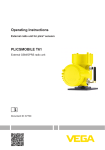
1
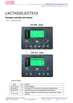
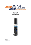
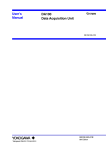
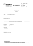
AcuDC 200 Series Power Meter User’s Manual Your Power and Automation Partner This manual may not be altered or reproduced in whole or in part by any means without the expressed written consent of Accuenergy. The information contained in this document is believed to be accurate at the time of publication, however, Accuenergy assumes no responsibility for any errors which may appear here and reserves the right to make changes without notice. Please ask the local representative for latest product specifications before ordering. [Document #1501E2122 Revision Date: Jul., 2012] I AcuDC 200 Series Copyright2012© V1.22 Accuenergy Tech. Ltd. AcuDC 200 Series Please read this manual carefully before doing installation, operation and maintenance of AcuDC 200 series DC meter. Safety Alert Symbol: Carries information about circumstances which if not considered may result in injury or death. Electric Shock Symbol: Carries information about procedures which must be followed to reduce the risk of electric shock and danger to personal health. DANGEROUS Potential Danger Symbol: Carries information about nearby hazards. Safety operation procedures must be followed to avoid personal injuries. Alarm Symbol: Carries information about user operation procedures which if not follow may cause malfunction of the meter and may result in injury. Installation and maintenance of the AcuDC 200 series DC meter should only be performed by qualified, competent personnel who receive appropriate training and should have experience with high voltage and current devices. II III AcuDC 200 Series Accuenergy shall not be responsible or liable for any damages cause by improper meter installation and or operation. AcuDC 200 Series Content Chapter 1 Introduction……………………………………………………………………………1 1.1 AcuDC 200 Overview………………………………………………………………………2 1.2 Application Area……………………………………………………………………………3 1.3 AcuDC 200 Series……………………………………………………………………………4 Chapter 2 Installation………………………………………………………………………………5 2.1 Appearance and Dimensions………………………………………………………………6 2.2 Installation Method…………………………………………………………………………8 2.3 AcuDC 200 Wiring Diagram………………………………………………………………14 2.3.1 Auxiliary Power Requirement………………………………………………………15 2.3.2 Voltage and Current Input…………………………………………………………17 2.3.3 I/O Setting……………………………………………………………………………22 2.3.4 Communication……………………………………………………………………28 Chapter 3 Basic Operation and Setup……………………………………………………………33 3.1 Display Panel and Keys……………………………………………………………………34 3.2 Real-Time Metering Mode ………………………………………………………………36 3.3 Parameter Setting Mode…………………………………………………………………37 IV Appendix…………………………………………………………………………………………65 Appendix A Technical Data and Specification………………………………………………66 Appendix B Ordering Information……………………………………………………………70 Appendix C Hall Effect Sensor Specifications…………………………………………………72 Appendix D Revision Information……………………………………………………………76 V AcuDC 200 Series Chapter 4 Communication……………………………………………………………………47 4.1 Modbus Protocol Introduction……………………………………………………………48 4.2 Communication Format…………………………………………………………………52 4.3 AcuDC 200 Address Table………………………………………………………………… 60 AcuDC 200 Series Starting! Congratulations! You have purchased an advanced, versatile, multifunction power meter. This meter can work as a remote terminal unit (RTU) that contributes to your system's stability and reliability by providing real-time power quality monitoring and analysis. When you open the package, you will find the following items. 1. AcuDC 200 series meter 2. Removable 14 pin terminal 3. Installation clips 4. User’s manual 5. Maintenance guarantee card 1 1 2 1 1 Please read this manual carefully before operating or installing the AcuDC 200 meter to avoid unnecessary trouble. You can read part of this manual depends on how you use the AcuDC 200 meter. Chapter 1 Basic function, specification and application area of AcuDC 200 meter. VI AcuDC 200 Series Chapter 2 Installation and wiring details of AcuDC 200 meter. Chapter 3 Real-time metering data display and parameter setting method of AcuDC 200 meter. Chapter 4 Communication protocol format and address table of AcuDC 200. Appendix Technical data and specifications of AcuDC 200 and ordering information. VII AcuDC 200 Series VIII AcuDC 200 Series Chapter 1 Introduction 1.1 AcuDC 200 Overview 1.2 Application Area 1.3 AcuDC 200 Series 1 1 AcuDC 200 Series 1.1 AcuDC 200 Overview Powerful Multifunction Power Meter AcuDC 200 Series multifunction intelligent power meter can measure DC voltage and current with high accuracy. Analog output can be used in DCS system or industry control system. Large character LCD display with backlight provides clear real-time monitoring data readout. This DC meter is designed to meet the requirement for DC power measurement and monitoring. Small Size and Easy Installation With the size of DIN96 ×48 and 71mm depth after mounting, the AcuDC 200 meter can be installed in a small gear. Fixing clips are used for easy installation and removal. Ease of Use AcuDC 200 utilizes a large character LCD display for clear electrical parameters readout. All setting parameters are accessible by using front panel keys or 2 High safety, high reliability AcuDC 200 meter was designed according to industry standards. The meter receives IEC and UL emission and immunity compliances and is able to operate reliably under high power disturbance condition. 1.2 Application Area Solar and Wind Energy Systems Industry Control Systems DC Energy Management Systems Large UPS Systems 3 AcuDC 200 Series communication port (if equipped). Setting parameters are protected in EEPROM, which will maintain its content after the meter is powered off. With the backlight of the LCD, the display can be easily read under dim environment. The backlight "ON" time duration is programmable. AcuDC 200 Series 1.3 AcuDC 200 Series This manual is based on AcuDC 223. Other models may not contain certain functions, please refer to the following table for details: Function Parameter Voltage (V) Current ( I ) Power (P) Energy(E) DI RO 4~20mA /0~5V Measuring I/O options AO Alarm Communication LCD display ● 4 function AcuDC AcuDC AcuDC 221 222 223 RS485 MODBUS ☉ option Blank NA ● ● ● AcuDC 211 AcuDC AcuDC 212 213 ● ● ● ● ● ● ● ● ● ☉ ☉ ☉ ☉ ☉ ☉ ☉ ☉ ☉ ☉ ☉ ☉ ☉ ☉ ☉ ● ● ● ☉ ☉ ☉ ● ● ● AcuDC 200 Series Chapter 2 Installation 2.1 Appearance and Dimensions 2.2 Installation method 2.3 AcuDC 200 Wiring Diagram 2.3.1 Auxiliary Power Requirement 2.3.2 Voltage and Current Input 2.3.3 I/O Setting 2.3.4 Communication 5 5 AcuDC 200 Series 2.1 Appearance and Dimensions The installation method is introduced in this chapter. Please read this chapter carefully before installation work. Appearance ⑧ ② Accuenerg y ③ V/A P E ④ ① ⑤ ⑦ ⑥ Figure2.1 Appearance of AcuDC 200 meter 6 AcuDC 200 Series Table2.1 Part name of AcuDC 200 meter Part Name 1. Enclosure 2. Front Casing 3. LCD Display 4. Key 5. Key Cover 6. Installation Clip 7. Input Terminals 8. Extend Wiring Terminals Description The AcuDC 200 meter enclosure is made of high strength anticombustion engineering plastic Visible portion (for display and control) after mounting onto a panel Large bright blue backlight LCD display Four keys are used to select display and to set parameters of the meter Close the cover to avoid wrong key operation Use for locating the meter to the panel Auxiliary power, voltage and current input Communication: DI,RO,AO 7 AcuDC 200 Series 48.00 ( 1.89'') ( 1.89'') 48.00 Dimension (mm/inch) 60.00 (2.36'') 96.00 (3.78'') 71.00 (2.80'') Figure 2.2 Dimension of AcuDC 200 2.2 Installation Method Environment Before installation, please make sure that the environment meets the following conditions. 8 AcuDC 200 meter’s working temperature range is from -25⁰C to 70⁰C. Operating the meter beyond this range may result in abnormal performance or damaging meter permanently. AcuDC 200 meter’s storage range is from -40⁰C to 85⁰C. 2. Humidity AcuDC 200 meter’s working humidity range is from 0 to 95% non-condensing. 3. Position AcuDC 200 meter should be installed in a dry and dust free environment. Avoid exposing meter to excessive heat, radiation and high electrical noise source. 9 AcuDC 200 Series 1. Temperature AcuDC 200 Series Installation Steps AcuDC 200 Series meter is typically installed on the panel of switch gear. 1. Cut a rectangular hole on the panel of the switch gear. cut 0.5 90 +0.5 90± -0.0 0.0 panel 0.50.5 Fig 2.3 Panel Cutting 10 0.5 44 +0.5 -0.0 The cutting size is as fig 2.3, Unit: mm (inch). u Acc Panel r ene gy 0 19 EV Fig 2.4 Put the meter into the rectangular hole 3. Install clips back to the meter from the backside and push the clip tightly so that the meter is fixed on the panel. 11 AcuDC 200 Series 2. Remove installation clips from the meter and insert the meter into the rectangular hole from the front side. AcuDC 200 Series Fig 2.5 Use the clips to fix the meter on the panel Space required for Installation There should be enough spacing for users to run wires to the meter, install and remove wiring terminal connectors, and operate the meter without interfering or damaging nearby equipment. Recommended minimum space around the meter is shown in Table2.2 and Fig 2.6. 12 AcuDC 200 Series Side Fig 2.6 Space around the meter Table 2.2 Minimum Space temperature <50⁰C ≥50⁰C a 25 38 b 25 38 Minimum distance(mm) c d e 38 64 25 51 76 38 f 25 38 13 AcuDC 200 Series 2.3 AcuDC 200 Wiring Diagram There are two terminal strips at the back of AcuDC 200. Top diagram: I/O ports and Communication terminals. DIGITAL INPUTS AO RELAY OUTPUTS RS-485 DI1+ DI2+ DI3+ DI4+ DIC AO+ AO- R11 R12 R21 R22 A B S 9 10 11 12 13 14 15 16 17 18 19 20 21 22 Bottom diagram: Power, Voltage Input and Current Input ports. POWER L 1 N 2 G 3 NC 4 VOLTAGE INPUT V+ V5 6 Note: NC means no connection Fig 2.7 Wiring terminals 14 CURRENT INPUT I8 I+ 7 Before setting up the meter's wiring, please make sure that the switch gear has an earth ground terminal. Connect both the meter's and the switch gear's ground terminal together. The following ground terminal symbol is used in this user’s manual. 2.3.1 Auxiliary Power Requirement DANGEROUS Only the qualified personnel could do the wire connection work. Make sure the power supply is cut off and all the wires are electroless. Failure to observe it may result in severe injury. There are 2 options for the Auxiliary Power Supply for the AcuDC 200 series meter: 1. Standard: 100 - 240Vac (50/60Hz) or 100-300Vdc 2. Low Voltage DC Option: 20-60Vdc The 2 options must be chosen according to the application. Please see the ordering information appendix for further details. The first option is mainly used under illumination power conditions, the other is used under accumulator battery conditions. Typical power consumption of the 15 AcuDC 200 Series Safety Earth Connection AcuDC 200 Series meter is less than 2W. A regulator or a UPS should be used when the power supply undulates too much. Pin numbers for the auxiliary power are 1, 2 and 3 (L, N, G). A switch or circuit-breaker shall be included in the building installation, in close proximity to the equipment, and within easy reach of the operator. It shall be marked as the disconnecting device for the equipment. 1A FUSE Note Make sure the voltage of power supply is the same as what the meter needed for its auxiliary power. Power Supply 1 L 2 N 3 G AcuDC 200 Fig 2.8 power supply Note Make sure the auxiliary p owe r te r m i n a l G i s connected to the earth ground terminal of the switch gear. 16 A fuse (typical 1A/250Vac) should be used in auxiliary power supply loop. No.3 terminal must be connected to the ground terminal of switch gear. 1 L 2 N 3 G EMI FILTER 1A FUSE Power Supply L 1 L N 2 N AcuDC 200 G 3 G Groud Fig 2.9 power supply under EMI filter Choice of power supply wire could be AWG22-16 or 0.6-1.3mm2. 2.3.2 Voltage and Current Input Voltage is directly input into the meter or via hall effect sensor. The wiring diagram is as follows: 17 AcuDC 200 Series An isolated transformer or EMI filter should be used in the auxiliary power supply loop if there is power quality problem in the power supply. AcuDC 200 Series Vdc+ VdcVoltage Hall Effect Sensor _ + Output Input + _ 1 V+ AcuDC 240 3 V- External DC Power Voltage Wiring using Voltage Hall Effect Sensor Fig 2.10 Voltage wiring There are three wiring configurations for current: 1) Direct Input (shown in Fig 2.11); 2) Current Shunt option (shown in Fig. 2.12); 3) Hall Effect Sensor option (shown in Fig 2.13) 18 vdc+ vdc- AcuDC 200 Series vdc+ vdc- 8 Ishunt 75mV AcuDC 200 7 I+ Load Fig 2.11 Current direct input wiring 8 I- 7 I+ AcuDC 200 Load Fig 2.12 Current input wiring with Shunt 19 AcuDC 200 Series Vdc+ Vdc- Current Hall Effect Sensor + Output _ Load 7 I+ AcuDC 200 8 I External DC Power Fig 2.13 Current input wiring with Hall Effect Sensor Wiring diagrams shown in Fig 2.14, 2.15 and 2.16 represent different scenarios in which both voltage input and different current input options are used. Fig 2.17 is voltage and current input with voltage and curret Hall Effect Sensors. 20 6 7 6 7 AcuDC 200 AcuDC 200 8 8 Load Fig 2.14 Voltage and Current direct input Fig 2.15 Voltage and Current input with Shunt Vdc+ Vdc+ Vdc- Vdc- Voltage Hall Effect Sensor 5 V+ 6 Load Current Hall Effect Sensor V- Output AcuDC 200 7 I+ 8 I- External DC Power Fig 2.16 Voltage and Current input with Hall Effect Sensor Load Current Hall Effect Sensor + Output _ + + Input _ _ + _ External DC Power Output 5 V+ 6 VAcuDC 200 7 I+ 8 I- External DC Power Fig 2.17 Voltage and Current input with Hall Effect Sensors 21 AcuDC 200 Series 5 5 AcuDC 200 Series Current direct input wiring is used for current smaller than 10A, the current signal wire choose AWG 15~16 or 1.5~2.5 mm2 or greater corss section. Current wiring using shunt method is used for current larger than 10A, the current signal wire choose AWG 15~16 or 1.5~2.5mm2 or the same resistance rate wire. 2.3.3 I/O Setting Digital Input External power supply is required for the 4 Digital Inputs (if equipped) of the AcuDC 220 Series. Input terminals are DI1+(9), DI2+(10), DI3+(11), DI4+(12), DIC(13). The circuit drawing of the digital input is simplified as fig 2.17. k DI+ Photo Coupler 16~30Vdc + COM OUT AcuDC 200 22 Fig 2.18 Simplified DI input circuit Relay Output Two relay outputs (RO), R11,R12 (terminal 16, 17) and R21, R22 (terminal 18,19), can be added to the meter as options. ROs can be used as remote control electric switches in power systems. Relay type is mechanical Form A contact with 3A/250V or 3A/30Vdc. A mediate relay is recommended in the output circuit as in Fig 2.18. 23 AcuDC 200 Series The external power supply voltage range for DI is from 16Vdc to 30Vdc. In order to compensate for interference, voltage of the external power supply may be higher when the DI's load is located at a distance; however, the maximum currert for the circuit must not be over 20mA. Wires with cross-section of 0.6~1.5mm2 (AWG 16~22) should be used for DI. AcuDC 200 Series R11 auxiliary power _ + mediate relay 27 AcuDC 200 R12 28 wires of mediate relay Fig 2.19 Relay Output The two relays in AcuDC 200 Series can be used to control field switches or other devices. The maximum mechanical response time for the relay is 3ms. Three output modes are available: latching, momentary and alarming. For latching mode, two output status are available: "ON" and "OFF". For momentary mode, output of the relay changes from "OFF" to "ON" for a time interval of "Ton" then goes back to "OFF". "Ton" can be set from 30~5000ms. Output mode and pulse width can only be set through communication. The alarming mode will be discussed in detail in the following chapter under the "alarming" section. The wire of relay output should be chosen between AWG22 (0.5mm2)~AWG16 (1.5mm2) 24 One analog output (AO) channel can be added to the AcuDC 200 meter as an option. Two types of AO signals are available: 4-20mA or 0~5V. Each meter can only support one type of output (either 4~20mA option or 0~5V option). Please specify your analog output requirement before ordering. Analog output can track voltage, current and power. The output range is fixed(4~20mA or 0~5V),but the input range can be set due to different applications. Setting procedure is as follows: Analog output settings can be modified by pressing the front panel keys on all AcuDC 200 Series models. In addition to front panel key pressing, AcuDC 220 Series' setting can be modified using RS485 communication. 1. Select track object: voltage, current or power. 2. Set tracking for the upper and lower limit. Maximum upper limit values for voltage, current and power are 600V, 9999A, 6000kW respectively. The upper limit must be less than the maximum upper limit value and greater than the lower limit 25 AcuDC 200 Series Analog Output AcuDC 200 Series value. The lower limit must be equal to or greater than 0. Appropriate upper and lower limit settings help to increase tracking accuracy and efficiency. 3. The relationship among AO output(out), upper limit(U) and lower limit(L) and measuring value(M) is as follows: 1): Voltage output option for AO: out=[(M-L)/(U-L)]*5V 2): Current output option for AO: out=4+[(M-L)/(U-L)]*16mA Two examples will be used to demostrate the above two relationships. AO tracking object and its setting is as follows: Table 2.3 Tracking object and its Setting number Setting number 0 1 2 26 Tracking object Voltage Current Power Set AO to track voltage, upper limit is 600V, lower limit is 0, when the measuring value is 300V, the AO output should be: out=[(M-L)/(U-L)]*5V=[(300-0)/(600-0)]*5V=2.5V. 2. Example 2: Current output option for AO Set AO to track power, upper limit is 10kW, lower limit is 4kW, when the measuring value is 6kW, the AO output should be: out=4+[(M-L)/(U-L)]*16mA=4+[(300-0)/(600-0)]*16mA=9.333mA. Note: 1. Upper limit must be greater than lower limit. 2. If measuring value is less than the lower limit, the output will be 0V/4mA. If the measuring value is greater than the upper limit, the output will be 5 V/20mA. 27 AcuDC 200 Series 1. Example 1: Voltage output option for AO AcuDC 200 Series VCC Vout VCC Load + Vout - R1 AcuDC 200 + - Load R2 Voltage Output AcuDC 200 R Current Output Fig 2.20 Analog Output Output Capability: 4~20mA, Max Load Resistance 500 Ohm; 0~5 V, Max Output Current 20mA. 2.3.4 Communication AcuDC 200 series uses RS485 serial communication and the Modbus-RTU protocol. The terminals of communication are A, B, and S (20, 21, 22). A is differential signal +, B is differential signal - and S is connected to shield of twisted pair cable. Up to 32 28 Typical RS485 network topologies include line, circle and star (wye). 1. Line AcuDC 200 meters are connected one by one (daisy chain format) from the master in the RS485 net as in fig 2.20. 232/485 Converter 232/485转换器 屏蔽双绞线 Shielded Cable 防反射电阻 Anti-reflecting Resistor Rt Ground 单点接大地 PC 主机 EV150 AcuDC 200 AcuDC 200 EV150 AcuDC 200 EV150 Fig 2.21 Line mode 29 AcuDC 200 Series devices can be connected on a RS485 bus. Use good quality shielded twisted pair cable, AWG22 (0.5mm2) or larger. The overall length of the RS485 cable connecting all devices cannot exceed 1200m (4000ft). AcuDC 200 is used as a slave device of master like PC, PLC, data collector or RTU. If the master does not have an RS485 communication port, a converter (such as a RS232/RS485 or a USB/RS485 converter) will be required. AcuDC 200 Series As shown in Fig 2.20, an anti signal reflecting resistor (typical value 120~300 ohm /0.25W) is added to the end of the circuit beside the last AcuDC 200 meter if the communication quality is distorted. 2. Circle AcuDC 200 meters are connected in a closed circle for the purpose of high reliability. No anti signal reflecting resistor is needed for circle mode. 232/485 Converter 232/485转换器 Shielded Cable 屏蔽双绞线 Ground 单点接大地 PC 主机 EV190 AcuDC 200 EV190 AcuDC 200 AcuDC 200 EV190 AcuDC 200 EV190 AcuDC 200 EV190 AcuDC 200 EV190 Fig 2.22 Circle mode 30 When connecting AcuDC 200 meters in the Wye mode, an anti signal reflecting resistor may be needed at the end of each line for better communication quality. 232/485 Converter 232/485转换器 屏蔽双绞线Shielded Cable Anti-reflecting Resistor Rt Ground 单点接大地 PC 主机 AcuDC 200 EV150 EV150 AcuDC 200 AcuDC 200 Rt EV150 AcuDC 200 AcuDC 200 EV150 AcuDC 200 Fig 2.23 Star mode A few points of recommendation for high quality communication are as follows: Good quality shielded twisted pair of cable AWG22 (0.6mm2) or larger is very important. 31 AcuDC 200 Series 3. Star AcuDC 200 Series The shield of each segment of the RS485 cable must be connected to the ground at one end only. Make sure the right connection of each point. Avoid T connection at each point. Keep cables away as much as possible from sources of electrical noise. An anti signal reflecting resistor (typical value 120~300ohm/0.25W) is normally added to the end of the circuit beside the last meter if the communication quality is distorted. Use RS232/RS485 or USB/RS485 converter with optical isolated output and surge protection 32 Chapter 3 Basic Operation and Setup 3.1 Display Panel and Keys 3.2 Real-Time Metering Mode 3.3 Parameter Setting Mode 33 AcuDC 200 Series 3.1 Display Panel and Keys The front of the meter consists of a LCD display panel and four control keys. All the display segments are illustrated in fig 3.1. 6 2 7 V 1 Kwh A KW max 5 min 1 2 3 4 addr bps 4 3 Fig 3.1 All Display Segments Table 3.1 Display Panel Description Numer Display 1 Data and Parameters 2 Unit Icon 34 Description Display metering data in metering mode. Indicating metering data unit, "V" for voltage, "A" for current, "KW" for Power, "Kwh" for Energy. 6 Limit Sign Upper/Lower limit value settings for AO. Digital Input Indicator No.1 to No.4 switches indicate status for DI1 to DI4 respectively. Parameter Icon "SET" icon and one of the following icons will be on at the same time in the setting mode. "addr" stands for device communication address setup; "bps" stands for communication rate setup; "A" stands for shunt current; "V" stands for shunt voltage. When setting up AO tracking object, "A" stands for tracking current and "V" stands for tracking voltage. Time for Backlight " icon is on, it indicates the time set for backlight. When " 7 Communication Icon When" " blinks, it indicates that communication is established between the meter and the master device. Users can read real-time metering data, set parameters and navigate the meter using the four control keys: , E, P and V/A from left to right respectively. The four keys are located underneath the key cover on the meter front. Note: This manual is written based on the AcuDC 223 (with full options) model. Some real-time metering display and parameter settings may not be available on certain models. 35 AcuDC 200 Series 3 4 5 AcuDC 200 Series 3.2 Real-Time Metering Mode Depending on model, the AcuDC 200 Series meter can display real-time metering data such as voltage, current, power and energy. When the meter is powered up, the default display parameter is either voltage or current (depends on model). LCD display backlight will turn on for the preset amount of time when any one of the four keys is pressed. Press V/A: First screen: Voltage display page. Voltage display: U=220.3V, Communication established; DI1 to DI4 are in the "OFF" state. Fig 3.2 Voltage Display Second screen: Current display page. A 36 Fig 3.3 Current Display Current display: As in fig 3.3, I=9.487A. DI2 and DI4 are "ON" whereas others are "OFF". Note: Communication icon blinks when the meter is communicating with the master Press P: Power display page. The picture shows that: P=350.6KW; DI1,DI3 are close; DI2, DI4 are open. Communication established. Fig 3.4 Power display Press E: Energy display page The picture shows: E=32768.9Kwh; all DIs are open. Communication established. Note: When the energy is greater than 99999.9Kwh, it will reset to 0 automatically. Fig 3.5 Energy display 3.3 Parameter Setting Mode and V/A to go to the parameter setting mode. In metering mode, Press 37 AcuDC 200 Series device. The blinking speed is relative to the data transfer rate. The faster the icon blinks, the higher the transfer rate is. AcuDC 200 Series Press to move cursor from left to right. The digit will be flashing when the cursor moves to it. Press E to increase 1 once a time. Press P to decrease 1 once a time. Press V/A to store the current setting and go to next screen. In any screen, press and V/A at the same time to exit the parameter setting mode. addr Fig 3.6 Local address Fig 3.7 Password input 38 Pa r a m e t e r s e t t i n g m o d e i s p a s s w o r d protected. Before entering the password and getting into the parameter setting mode, the meter's device communication address will display for 3 seconds as shown in Fig 3.6 A four digit password (0000 to 9999) is required everytime before accessing the parameter setting mode. The default password is 0000. The meter will return to the metering mode if a wrong password is entered. Password input page shown in Fig 3.7. 39 AcuDC 200 Series First Screen: Communication address setting. The address can be any integer between 1 and 247. As in fig 3.8, the communication address is 84. To change the address, press addr to move cursor, press P to increase the Fig 3.8 Communication Address Setting value by 1 and press E to decrease value by 1. Press V/A to store the current address and go to the next setting screen. Press V/A to go to the next screen if there is no need to change the address. Note: No more than two meters can have the same communication address on the same communication line according to the Modbus-RTU protocol. The second screen: Baud rate setting page. Modbus-RTU uses 8 data bit, no parity, 1 start bit and 1 stop bit. Baud rate can be selected from one of the five values:1200, 2400, 4800, 9600, 19200bps. Press P or E Fig 3.9 Baud rate setting page to select a suitable baud rate. Press V/A to go to next screen. Same baud rate should be used for all the meters on the same communication line. AcuDC 200 Series A Fig 3.10 Shunt current input full range setting V Fig 3.11 Shunt/Hall Effect Sensor output setting The third screen: Shunt / Hall Effect Sensor current input full range setting. The value input is the full range current value for the Shunt or Hall Effect Sensor. AcuDC 200 series support 1~9999A shunt. The value range in this screen is 1~9999. The fourth screen: Shunt / Hall Effect Sensor output voltage setting. The value input is the full range output voltage value for the Shunt or Hall Effect Sensor. For instance, 100mV shunt, enter 100; 5V Hall Effect Sensor, enter 50; 20mA Hall Effect Sensor, enter 20. AcuDC 200 series support 50~100mV arbitury voltage shunt. If it exceeds this range, the value will be reset to default 100. Our recommendation for shunt is 100mV shunt, it is better for accuracy. 40 The value here for shunt, the range is 50~100; for volage Hall Effect Sensor, the range is 1~100; for current Hall Effect Sensor, the range is 4-100. 4~XmA and 0~XmA types are not exchangable. SET The fifth screen: AO output setting. Please refer to “Analog output” in chapter two for detail information. Fig 3.12 AO output setting A The sixth screen: AO tracking lower limit setting page. Min Fig 3.13 AO tracking lower limit A Max The seventh screen: AO tracking upper limit page. Fig 3.14 AO tracking upper limit 41 AcuDC 200 Series A AcuDC 200 Series Kwh Fig 3.15 Energy clear page 42 The eighth screen: Energy clear page. It displays “CLE” and a digit at the same time. No change will be made if the digit is set to 0. Energy will be reset after pressing V/A if the digit is set to 1. The ninth screen: Backlight "ON" time setting page. The LCD display backlight will turn "OFF" after inactive for a period of time to conserve energy. The "ON" time can be set from 0 to 120 minute. The backlight will always be "ON" Fig 3.16 Back light “ON” time if the setting value is 0. As in fig 3.16, the setting time of the backlight is 5 minutes. The backlight will automatically turn "OFF" if no key activation within 5 minutes. The tenth screen: only when the meter voltage wiring is via voltage Hall Effect Sensor, there will be this screen. Otherwise, there is no such screen. The voltage input range is 0~1200Vdc. Fig 3.17 shows the voltage input is 1000V. Fig 3.17 Voltage Hall Effect Sensor setting As in fig 3.17, the password is 0001. Press V/A to store the new password and return back to and V/A keys to exit the first setting page. After finishing all of the settings, press the setting mode. Fig 3.17 Password setting Alarming AcuDC 200 Series meter can be used for alarming. Over/under limit alarm will be triggered when the metering parameter value falls outside of the preset value limit and does not resume back to normal within the preset time delay interval. When an alarm condition is met, the alarm channel relay will be activated (switch close) and the LCD display backlight will flash. Alarm setting steps are as follows: 43 AcuDC 200 Series The tenth screen: Password setting page. This is the last screen in setting mode. The password can be changed in this page. It is important to remember the new password. AcuDC 200 Series 1. Set RO output mode to alarming (2). 2. Select alarming object. For example: voltage for AcuDC 221 (1); current for AcuDC 222 (2). 3. Set alarming delay time (0~255s) 4. Set alarming limit value. 5. Sign of inequality selection. 6. RO alarm channel selection (0: RO1; 1: RO2; 2: RO1, RO2). Alarming parameters Address 0105H 0106H 0107H 0108H 010BH 010CH 44 Parameter RO1 output mode Pulse width of RO1 RO2 output mode Pulse width of RO2 Alarming object Sign of inequality Range 0-level, 1-pulse, 2-alarming 30~5000ms 0-level, 1-pulse, 2-alarming 30~5000ms 0: no; 1: voltage; 2: current; 3: power 0: <, 1: > Alarming value 010DH 010EH Alarming delay time RO alarm channel AcuDC 200 Series 010FH 0100H current: 0~9999.0 voltage: 0~600.0 power: 0~ 6000.0 0~255 s 0~RO1; 1~RO2; 2~RO1,RO2 Here is an example to show how this works If we want to trigger an alarm at RO1 when the current is over 10.005A with a time delay of 15 seconds, we should set the alarm parameters as follows: 1) Set RO1 output mode to 2 (This means RO1 works under alarming mode). 2) Set alarming object to 2 (current). The alarming limit value should be set as 10.005. 3) Set alarming delay time as 15 seconds. 4) Set sign of inequality to 1. 5) Set RO alarm output channel as 0. After setting up the alarm parameters, when the alarm condition is met (current goes above 10.005A for 15 seconds), RO1 will be activated (contact closed) and the 45 AcuDC 200 Series LCD display backlight will flash. Note: If "RO alarm output channel" is set as 2 and RO1 is set to alarming mode, when an alarm condition is met, the alarm signal will be sent to both of the relay outputs but only RO1 will be triggered (since RO2 is not in alarming mode). If none of the relay output is set to alarming mode, no relay will be triggered. 46 AcuDC 200 Series Chapter 4 Communication and Setup 4.1 Modbus Protocol Introduction 4.2 Communication Format 4.3 AcuDC 200 Address Table 47 47 AcuDC 200 Series 4.1 Modbus Protocol Introduction The ModbusTM RTU protocol is used for communication in the AcuDC 200 series meter. Data format and error check methods are defined in Modbus protocol. The half duplex query and respond mode is adopted in Modbus protocol. There is only one master device in the communication net. The others are slave devices, waiting for the query of the master. Only the master device can communicate with slave devices. The slave devices cannot communicate with each other. They can only response to the query of master device. 1. Transmission mode The mode of transmission defines the data structure within a frame and the rules used to transmit data. The mode is defined in the following which is compatible with Modbus RTU Mode*. Coding System Start bit Data bits 48 8bit Parity 1bit Stop bit 8bit Error checking None 1bit CRC AcuDC 200 Series 2. Protocol Framing Table 4.1 Data Framing Address 8-Bits Function 8-Bits Data N x 8-Bits Check 16-Bits Address Field The address field of a message frame contains eight bits. Valid slave device addresses are in the range of 1~247 decimal. A master addresses a slave by placing the slave address in the address field of the message. When the slave sends its response, it places its own address in this address field of the response to let the master know which slave is responding. Function Field The function code field of a message frame contains eight bits. Valid codes are in the range of 1~255 decimal. When a message is sent from a master to a slave device the function code field tells the slave what kind of action to perform. 49 AcuDC 200 Series Table 4.2 Function Code Code 01 02 03 05 16 Meaning Read Relay Output Read Digital Input Read Registers Control Relay Output Preset Multiple-Registers Action Obtain current status of Relay Output Obtain current status of Digital Input Obtain current binary value from one or more registers Force relay state to "ON" or "OFF" Place specific binary values into a series of consecutive Multiple-Registers Data Field The data field is constructed using sets of two hexadecimal digits, in the range of 00 to FF hexadecimal. The data field of messages sent from a master to slave devices contains additional information which the slave must use to take the action defined by the function code. This can include items like discrete and register addresses, the quantity of items to be handled, and the count of actual data bytes in the field. Check Field 50 Check field is used in the master and slave device to find errors in the data transmitting. Inaccuracy may occur within a data group due to noise or other 3. Error Check Method Every message includes an error checking field which is based on the Cyclical Redundancy Check (CRC) method. The CRC field checks the contents of the entire message. It is applied regardless of any parity check method used for the individual characters of the message. The CRC field is two bytes long, containing a 16-bit binary value. The CRC value is calculated by the transmitting device, and is appended to the message. The receiving device recalculates the CRC value during reception of the message, and compares the calculated value to the actual value it received in the CRC field. If the two values are not equal, an error will be reported. CRC calculation is first started by preloading the whole 16-bit register to 1’s. The process begins by applying successive 8-bit bytes of the message to the current contents of the register. Only the eight bits of data in each character are 51 AcuDC 200 Series interference when being transitted from one device to another. The check field guarantees the device does not respond to error messages in order to improve system reliability and efficiency. CRC16 error check method is adopted in Modbus Protocol. AcuDC 200 Series used for generating the CRC. Start and stop bits, and the parity bit, do not apply to the CRC. When generating the CRC, each 8-bit character is exclusive ORed with the register contents. The result is shifted towards the least significant bit (LSB), with a zero filled into the most significant bit (MSB) position. The LSB is extracted and examined, if the LSB equals to 1, the register is exclusive ORed with a preset, fixed value; if the LSB equals to 0, no action will be taken. This process is repeated until eight shifts have been performed. After the last (eighth) shift, the next 8-bit byte is exclusive ORed with the register's current value, and the process repeats for eight more shifts as described above. The final contents of the register, after all the bytes of the message have been applied,the final contents of the register, which should exchange the high-byte and the low-byte, is the CRC value. When the CRC is appended to the message, the low-order byte is appended first, followed by the high-order byte. 4.2 Communication Format All examples shown in this chapter follows the same format of Table 4.3. (All data is express in Hex) 52 AcuDC 200 Series Table 4.3 Protocol Format Addr Fun 11H 03H Data start reg HI 01H Data start reg LO 00H Data #of regs HI 00H Data #of regs LO 08H CRC16 HI 47H CRC16 LO 60H The meaning of each abbreviated word is, Addr: Address of slave device Fun: Function code Data start reg HI: Start register address high byte Data start reg LO: Start register address low byte Data #of reg HI: Number of register high byte Data #of reg LO: Number of register low byte CRC16 HI: CRC high byte CRC16 LO: CRC low byte 53 AcuDC 200 Series 1. Read Status of Relay (Function Code 01) Query This function code is used to read status of relay in the meter. 1=On 0=Off There are 2 relays in the meter. The address of each relay is: Relay1=0000H and Relay2=0001H. The following query is to read the relay status for the meter with communication address 17. Table 4.4 Read the status of Relay1 and Relay2 Query Message Addr Fun 11H 01H DO start reg HI 00H DO start reg LO 00H DO #of regs HI 00H DO #of regs LO 02H CRC16 HI BFH CRC16 LO 5BH Response The meter response includes the meter address, function code, quantity of data byte, the data, and error checking. An example response to read the status of Relay1 and Relay2 bits is shown as Table 4.5. The status of Relay1 and Relay2 is 54 AcuDC 200 Series responding to the last 2 bits of the data. Relay1: bit0 Relay2: bit1 Table 4.5 Relay status responds Addr 11H Fun 01H Byte count 01H Data 02H CRC16 HI D4H CRC16 LO 89H The content of the data is, 7 0 6 0 5 0 4 0 3 0 MSB (Relay 1 = OFF , Relay 2=ON) 2 0 1 1 0 0 LSB 2. Read Status of DI (Function Code 02) Query 1=On 0=Off There are 4 DIs in the meter. The address of each DI is DI1=0000H, DI2=0001H, DI3=0002H and DI4=0003H. The following query is to read the 4 DI status of the meter with communication address 17. 55 AcuDC 200 Series Table 4.6 Read the status of DI1~DI4 Query Message Addr Fun 11H 02H DI start addr HI 00H DI start addr LO 00H DI num HI 00H DI num LO 04H CRC16 HI 7BH CRC16 LO 59H Response The AcuDC 200 response includes the AcuDC 200 address, function code, quantity of data characters, the data characters, and error checking. An example response to read the status of 4 DIs is shown in Table 4.7. The DI status corresponds to the last 4 bits of the data. DI1: bit0 DI2: bit1 DI3: bit2 DI4: bit3 Table 4.7 Read Status of DI Addr 11H Fun 02H Byte count 01H 6 0 5 0 Data0 03H CRC16 HI E5H CRC16 LO 49H Data 7 0 56 MSB 4 0 3 0 2 0 1 1 0 1 LSB Query This function allows the master to obtain the measurement results from the meter. Table 4.8 is an example to read the measured data from slave device number 1, the data address for voltage V is 0200H. Table 4.8 Read V Query Message Addr Fun 01H 03H Data start addr HI 02H Data start Addr LO 00H Data # of regs HI 00H Data # of regs LO 01H CRC16 HI 85H CRC16 LO B2H Response The meter response includes the meter address, function code, quantity of data byte, data, and error checking. An example response to read V=0001H (0.01V) is shown in Table 4.9. Table 4.9 Read V Message Addr Fun 01H 03H Byte count 02H Data HI 00H Data LO 01H CRC16 HI 79H CRC16 LO 84H 57 AcuDC 200 Series 3. Read Data (Function Code 03) AcuDC 200 Series 4. Control Relay (Function Code 05) Query This message forces a relay to either turn "ON" or "OFF". Any relay that exists within the meter can be forced to either "ON" or "OFF" status. Relay addresses start at 0000H (Relay1=0000H Relay2=0001H). The data value FF00H will set the relay on and the value 0000H will turn it off; all other values are illegal and will not affect that relay. The example below is a request to the meter number 1 to turn on Relay1. Table 4.10 Control Relay Query Message Addr 01H Fun 05H DO addr HI DO addr LO 00H 00H Value HI FFH Value LO 00H CRC16 HI CRC16 LO 8CH 3AH Response The normal response to the command request is to retransmit the message as received after the relay status has been altered. Table 4.11 Control Relay Response Message 58 Addr 01H Fun 05H Do addr HI 00H Do addr LO 00H Value HI FFH Value LO 00H CRC16 HI 8CH CRC16 LO 3AH Query Function 16 allows the user to modify the contents of a multi-register. Any register that exists within the meter can have its contents changed by this message. The example below is a request to meter number 1 to preset alarming value(1000), alarming delay(4s), and alarming output to RO1. Table 4.12 Preset / Reset Multi-Register Message Addr Fun 01H 10H Value1 HI 07H Value1 LO D0H Data start reg HI 01H Value2 HI 00H Data start reg LO 0BH Value2 LO 05H Data # of reg HI 00H Value3 HI 00H Data # of reg LO 03H Value3 LO 01H Byte Count CRC HI 82H 06H CRC LO 3DH Response The normal response to a preset multi-register request includes the slave address, function code, data start register, the number of registers and error checking. 59 AcuDC 200 Series 5. Preset / Reset Multi-Register (Function Code 16) AcuDC 200 Series Table 4.13 Preset Multi-Registers Response Message Addr Fun 01H 10H Data start reg HI 01H Data start reg LO 0B H Data #of reg HI 00H Data #of reg LO 03H CRC16 HI F0H CRC16 LO 36H 4.3 AcuDC 200 Address Table Metering data is stored in these register areas. Use Modbus function code 03 to read metering data. Table 4.14 Metering data address table Address 0200H,0201H 0202H,0203H 0204H,0205H 0206H,0207H Parameter Voltage V Current I AO output Power Range Object Type Float Float Float Float Type of Access R R R R The relationship between the numerical value in the register of AcuDC 200 and the real physical value is shown in table below. (Rx is the numerical value in register of the meter) 60 AcuDC 200 Series Table 4.15 Metering data convert table Parameter Voltage V Current I Power Energy AO output Relationship Real =Rx Real =Rx Real =Rx Real =Rx/100 Real =Rx unit V A kW kWh V or mA (related with AO pattern) Parameter Setting Function code: 03 for Reading,16 for Presetting Table 4.16 System parameter address Address Parameter Range 0100H 0101H 0102H Access Code Address Baud rate Shunt full range current input 0~9999 1~247 1200~19200 0~9999(A): input range of Shunt / Hall Effect Sensor 0: No shunt/HCT; 1~100: Full range output of shunt / hall effect sensor 0-level, 1-pulse, 2-alarming 0103H 0104H Shunt full range output voltage 0105H RO1 output mode Object Type Word Word Word Type of Access R/W R/W R/W Word R/W Word R/W Word R/W 61 AcuDC 200 Series 0106H 0107H 0108H Pulse width of RO1 RO2 output mode Pulse width of RO2 0109H AO output 010AH Backlight "ON" time 010BH Alarming object 010CH Sign of inequality 010DH Alarming delay time 010EH RO alarm channel 010FH, 0110H Alarming value 0111H, 0112H Lower limit of AO 0113H, 0114H Upper limit of AO 0115H, 0116H Energy presetting Voltage Hall Effect 0117H Sensor Input Voltage Hall Effect 0118H Sensor Output 62 30~5000ms 0-level, 1-pulse, 2-alarming 30~5000ms 0: no; 1: voltage; 2: current; 3: power 0~120minute 0: no; 1: voltage; 2: current 3: power 0: <, 1: > 0~255 s 0~RO1; 1~RO2; 2~RO1,RO2 The same as reading data The same as reading data The same as reading data 0~9999999 Word Word Word R/W R/W R/W Word R/W Word R/W Word Word Word Float Float Float Long R/W R/W R/W R/W R/W R/W R/W 0~1200V Word R/W 1~5V Word R/W AcuDC 200 Series Please refer to chapter 3 for more information. Digital Iput (DI) Status: Function code: 02 for Reading Table 4.17 Digital Input (DI) Address Address 0000H 0001H 0002H 0003H Parameter DI1 DI2 DI3 DI4 Range 1=ON, 0=OFF 1=ON, 0=OFF 1=ON, 0=OFF 1=ON, 0=OFF Object Type Bit Bit Bit Bit Type of Access R R R R Relay Status and Control Function code: 01 for Reading, 05 for Controlling. Table 4.18 Relay Address Address Parameter Range Object Type Type of Access 0000H 0001H DO1 DO2 1=ON, 0=OFF 1=ON, 0=OFF Bit Bit R/W R/W 63 AcuDC 200 Series Analog output: Function code: 03 for Reading, 16 for Presetting. Table 4.19 AO Address Address 0109H Parameter Transform object Range 0~2 Object Type Word Type of Access R/W Note: 1. Object type: Bit-binary bit, Word-unsigned integer of 16 bit, Integer-signed integer of 16 bit, Dword-unsigned integer of 32 bit. 2. Type of access: R-Read only; Relay Output (RO) status, Digital Input (DI) status and general measurement parameters can be read from memory using function code 01, 02 and 03 respectively. R/W - Read and Write; data can be read from and written into memory using function code 16. Control command can be written using function code 05. Writing to "Read only" field is forbidden. 64 Appendix Appendix A Technical Data and Specifications Appendix B Ordering Information Appendix C Hall Effect Sensor Specifications Appendix D Revision Information 65 AcuDC 200 Series Appendix A Technical Data and Specifications 1. Measurement Parameter Voltage Current Power Energy Accuracy 0.2% 0.2% 0.5% 0.5% Resolution 0.01V 0.005A 0.01W 0.1kWh 2. Communication Parameter Type Baud Rate Protocol Isolate Voltage Function 66 Description RS485, Half Duplex, Optical isolated 1200~19200bps Modbus-RTU 2500Vac Read and Write setting parameters Read measuring data Execute operation instruction Range 0~600V 0.005~9999A 0.01~6,000,000W 0.1~99999.9kWh AcuDC 200 Series 3. Output Output Form Max Load Voltage Max Load Current Contact Resistance Isolate Voltage Contact Material Mechanical Endurance Output Form Range Resolution Load Capability Max Resistance Max Current Relay Output (RO) Mechanical Contact, Form A 250Vac/30Vdc 3A 100mΩ(Max) 4000Vac silver alloy 5×10⁶ cycles latching or pulse (30 to 5000ms) or alarming Analog output (AO) 4~20mA or 0~5V 12bit 4~20 mA, 0~5 V 500Ω 20mA 67 AcuDC 200 Series 4. Input Current Shunt Hall Current Thruster (HCT) Power Consumption Accuracy Input Voltage Input Impedence Load Isolate Voltage Input Type Input Resistance Input Voltage Range Max Input Current 68 Current 0~10A(Direct Input), 0~9999A(Extra current shunt or HCT, with programmable range) 50~100mV(Programmable) 0~5V, 0~4V, 0~20mA, 4~20mA 2W(Max) 0.2% Voltage 0~600V 2MΩ < 0.2W Digital Input (DI) 2500Vac rms Wet contact (Contact with power supply) 2K ohm (typical) 16~30Vdc 20mA AcuDC 200 Series 5. Environment Parameter Humidity Temperature Size Package Weight Description 0~95% Non-condensing -25%⁰C~70⁰C 165mm×70mm×115mm 0.4Kg 6. Power Supply Parameter Option 1 Option 2 Power Consumption Input Description 100~240Vac, 50/60Hz; 100~300Vdc 20~60 Vdc 2W 69 AcuDC 200 Series Appendix B Ordering Information Voltage Current Aux. PowerSupply DI Opution RO Opution AO Opution AcuDC 200 0AO: No Analog Output AO1: 4-20mA AO2: 0-5V 0RO: No Relay Output 2RO: 2 Relay Output (AcuDC 221/222/223 Only) 0DI: No Digital Input 4DI: 4 Digital Input (AcuDC 221/222/223 Only) A0: A1: A2: A3: P1: 100 - 240Vac,50/60Hz,100- 300Vdc P2: 20 - 60Vdc Dierct Current Input(0~10Amp) Current Shunt Input Option (50~100mV) Hall Element Input Option(4~20mA) Hall Element Input Option( 0~5V) 300V: Nominal Input Volage 300 Vdc 600V: Nominal Input Volage 600 Vdc 48V: Nominal Input Volage 48 Vdc 5V: Via Hall Element Sensor (0-5V),ratio settable, Voltage Hall Element Sensor can be ordered AcuDC 211(Voltage Meter,No communication) AcuDC 212(Current Meter,No communication) AcuDC 213(Multifuncion,No communication) AcuDC 221(Voltage Meter, communication) AcuDC 222(Current Meter, communication) AcuDC 223(Multifuncion, communication) 70 AcuDC Series Meter Ordering Example: AcuDC 223 - 300V - A2 - P1 - 4DI- 2RO- AO1 Current Hall Effect Sensor Ordering Information Special order Special order Please contact your local Accuenergy Please contact your local Accuenergy Representative for further details Representative for further details AcuDC 200 Series Voltage Hall Effect Sensor Ordering Information Note: 1. When the input voltage is above 600V, or the system design requires an isolation, the voltage input can be selected as Via Hall Effect Sensor (0-5 V). The Voltage Hall Effect Sensor requires 0-5 V. 2. Hall Effect Sensors need external ±15Vdc power supply, which the customer must provide. 71 AcuDC 200 Series Appendix C Revision Information Revision 1.0 1.02 72 Date 20080215 20090305 Description First version Add content at P36 and P60 ; Add HCT content in this manual Revise content 1.03 20090610 1.20 20100422 Revise content 1.21 1.22 20100830 20120727 Change the address of Energy parameter Update the wiring diagram Update the method for generating CRC value Remove hall effect sensor ordering information and specifications Accuenergy Corporation Los Angeles-Toronto-Beijing North America Toll Free: 1-877-721-8908 Web: www.accuenergy.com Email: [email protected]