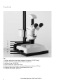
1
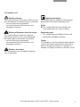
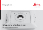
Transmitted
Light Bases
TL RC™ (MDG 32)
TL RCI™ (MDG 30)
User Manual
Contents
Page
Overviews
Safety concept . . . . . . . . . . . . . . . . . . . . . . . . . . . . . . . . . . . . . . . . . . 4
Symbols . . . . . . . . . . . . . . . . . . . . . . . . . . . . . . . . . . . . . . . . . . . . . . . . 5
Safety regulations . . . . . . . . . . . . . . . . . . . . . . . . . . . . . . . . . . . . . . . .6
Controls . . . . . . . . . . . . . . . . . . . . . . . . . . . . . . . . . . . . . . . . . . . . . . . 8
Assembly . . . . . . . . . . . . . . . . . . . . . . . . . . . . . . . . . . . . . . . . . . . . . . 10
Operation
Relief contrast . . . . . . . . . . . . . . . . . . . . . . . . . . . . . . . . . . . . . . . . . 12
Path-folding mirror . . . . . . . . . . . . . . . . . . . . . . . . . . . . . . . . . . . . . .12
IsoPro™ cross stage . . . . . . . . . . . . . . . . . . . . . . . . . . . . . . . . . . . .12
Light intensity and color temperature . . . . . . . . . . . . . . . . . . . . . .12
USB mouse . . . . . . . . . . . . . . . . . . . . . . . . . . . . . . . . . . . . . . . . . . . .13
Methods with transmitted light . . . . . . . . . . . . . . . . . . . . . . . . . . .14
Relief display . . . . . . . . . . . . . . . . . . . . . . . . . . . . . . . . . . . . . . . . . . .14
Filter . . . . . . . . . . . . . . . . . . . . . . . . . . . . . . . . . . . . . . . . . . . . . . . . . .16
Lamp replacement . . . . . . . . . . . . . . . . . . . . . . . . . . . . . . . . . . . . . .16
Care, maintenance . . . . . . . . . . . . . . . . . . . . . . . . . . . . . . . . . . . . . .17
Expansion diagram . . . . . . . . . . . . . . . . . . . . . . . . . . . . . . . . . . . . .18
Scope of delivery . . . . . . . . . . . . . . . . . . . . . . . . . . . . . . . . . . . . . . .19
Dimensioned drawing . . . . . . . . . . . . . . . . . . . . . . . . . . . . . . . . . . .20
Technical data . . . . . . . . . . . . . . . . . . . . . . . . . . . . . . . . . . . . . . . . . .22
2
Transmitted-light bases TL RC™ and TL RCI™ – Safety concept
Dear User
Thank you very much for your trust in Leica Microsystems.
We hope your work with our high-quality, efficient products is
both enjoyable and successful.
In developing our instruments, we have placed great weight on
simple, self-explanatory operation. However, take your time to
read the user manual, in order to familiarize yourself with the
optimal use of all the benefits and options of your stereo microscope. Should you have any questions, please consult your
local Leica representative. You will find the address of the closest local representative as well as valuable information about
products and services from Leica Microsystems on our homepage at www.leica-microsystems.com
We are gladly at your service. CUSTOMER SERVICE is a big
thing with us. Not only before the sale, but afterwards as well.
Leica Microsystems (Switzerland) Ltd.
Stereo & Macroscope Systems
www.stereomicroscopy.com
The user manual
This user manual is available in 20 additional languages on our
interactive CD-ROM.
User manuals and updates are also available for download on
our homepage at www.stereomicroscopy.com.
The user manual at hand describes the safety instructions,
assembly, and handling of the TL RC™ and TL RCI™ transmitted-light bases.
Transmitted-light bases TL RC™ and TL RCI™ – Safety concept
3
Safety concept
1.1 The user manual
The TL RC™ /TL RCI™ transmitted-light bases
come with an interactive CD-ROM containing all
relevant manuals in 20 additional languages. Keep
this CD-ROM in a safe place, where it is available
to the user. User manuals and updates are also
available for download and print-out on our
homepage at www.stereomicroscopy.com.
Before assembly, start up and use, please
read the user manuals cited above. In particular,
please observe all safety instructions.
To maintain the unit in its original condition and to
ensure safe operation, the user must follow the
instructions and warnings contained in these user
manuals.
The TL RC™ and TL RCI™ transmitted-light bases
are a module of the Leica M stereo microscope
series. This user manual describes the special
functions of the transmitted-light base and contains important instructions for operating safety,
maintenance and the accessory parts.
The M2-105-0 user manual for the Leica M stereo
microscopes contains additional safety rules for
the stereo microscope, accessories and electrical
accessories, as well as instructions for maintenance.
You can combine the transmitted-light base TL RC™
with any cold light source and a glass fiber light
guide (active f = 10mm, tail tube f = 13mm). Please
read the user manual and the safety requirements
of the supplier.
4
Transmitted-light bases TL RC™ and TL RCI™ – Safety concept
1.1.1 Symbols used
Warning of danger
This symbol indicates information, which must be
read and obeyed. Disregarding these instructions
– can cause hazards to personnel!
– can lead to functional disturbances and
damaged instruments.
Important information
This symbol indicates additional information or
explanations that intend to provide clarity.
Action
왘 This symbol within the text indicates that
certain operations must be carried out.
Warning of dangerous electrical voltage
This symbol indicates especially important
information, which must be read and obeyed
Disregarding these instructions can lead to
– can cause hazards to personnel!
– can lead to functional disturbances and
damaged instruments.
Explanatory notes
• This symbol indicates additional notes and
explanations provided in the text.
Figures
(1.5) Numbers in brackets within the descriptions
relate to the figures and the items within those
figures. Example (1.3): Figure 1 is located, for
example, on Page 8 and item 3 is the filter carrier.
Warning - hot surface
This symbol warns you of tangible, hot points,
such as light bulbs.
Transmitted-light bases TL RC™ and TL RCI™ – Safety concept
5
1.2 Safety regulations
Description
The transmitted-light bases TL RC™ and TL RCI™
fulfill the highest requirements for observation
and documentation of Leica stereo microscopes
of the M series. It contains a path-folding mirror,
a device for partial pupil illumination and relief
contrast generation, a ground-glass screen, an
additional condenser and Fresnel lenses. The
complete stand consists of:
– Transmitted-light base TL RC™ or TL RCI™
– Stand 300 mm or 500 mm long with focusing
drive, manual coarse/fine or motorized focus
– Glass stage plate, clear, 220×170×4mm
– Light source and light guide according to
requirements
Accessories:
– Gliding stage
– Leica MATS Thermocontrol System with
heating stage
– Polarization set
and many more (see Expansion diagram)
Intended uses
TL RC™ and TL RCI™ transmitted-light bases are
used in the assembly of Leica M series stereo
microscopes via tripod column and microscope
carrier. They can be combined with any cold light
source and light guide and allows you to observe
transparent specimen with relief contrast and
direct transmitted light. The TL RCI™ transmittedlight base posseses an integrated halogen lamp
that particularly supports control by Leica Application Suite (LAS) software.
Never:
– Change, rebuild or take apart parts, if not
specifically instructed to in this manual.
– Let non-authorized persons open parts of the
instrument.
– Use the transmitted-light base TL RC™/TL RCI™
for investigations and operations on the human
eye.
The units or accessory components described in
the user manual have been checked for safety
and possible dangers. Always consult the responsible Leica office or the main plant in Wetzlar at
any time there is a need to adjust the unit or it is
combined with non Leica components which go
beyond the scope of this manual.
Unauthorized adjustment of the unit or improper
use renders the warranty null and void.
Place of use
– Only use the transmitted-light base
TL RC™/ TL RCI™ in closed, dust free rooms
and between +10°C and +40°C. Make sure that
the rooms are free of oil vapors or other chemical vapors and extreme humidity.
– Set up the electrical components at least 10 cm
from walls and combustible objects.
– Avoid large temperature fluctuations, direct
sunlight and vibrations. This can cause faulty
measurements or microphotographs.
– In warm, or warm and humid climatic zones,
the transmitted-light base TL RC™/ TL RCI™
requires particular care to prevent formation
of fungus.
Prohibited uses
If you use the transmitted-light base
TL RC™/TL RCI™, its components, and the accessories in a way other than that described in the
user manual, harm may be caused to people or
objects.
6
Transmitted-light bases TL RC™ and TL RCI™ – Safety concept
Responsibilities of person in charge of the
instrument
Ensure that
– The transmitted-light base TL RC™/ TL RCI™
and the accessories are only operated, maintained and repaired by authorized and trained
personnel.
– Personnel who use the instrument have read
and understood this user manual and in particular the safety instructions and obey them.
Repairs, servicing work
– Repairs may only be carried out by servicing
engineers trained by Leica Microsystems or
your own authorized technical personnel.
– Only original Leica Microsystems parts may
be used.
– Before opening the devices, turn off power
and unplug mains cables.
If you touch the electric circuit of the
equipment, you may receive an electric shock.
Integration in third-party products
The following must be observed if Leica products
are built into third-party products: The manufacturer of the complete system or the person putting
it on the market is responsible for adhering to
applicable safety regulations, laws and guidelines.
Disposal
The products described here must be disposed off
in accordance with applicable local laws and regulations.
Legal requirements
Adhere to general and local regulations relating
to accident prevention and environmental protection.
EU declaration of conformity
The transmitted-light base TL RC™/ TL RCI™ and
the accessories have been constructed according
to the state of the art and issued with an EU declaration of conformity.
Transport
– Use the original packaging for shipping or
transporting the transmitted-light base TL RC™/
TL RCI™ and the accessory components.
– To prevent damage through vibrations, remove
and pack specially all the moving components
which you installed yourself, in accordance
with the user manual.
Transmitted-light bases TL RC™ and TL RCI™ – Safety concept
7
Controls
1
2
3
4
5
6
7
Fig. 1
1
2
3
4
5
6
7
8
Cooling element of integrated halogen illumination (TL RCI™ only)
Adapter plate for easy assembly of focusing drives
Standard stage 10 447 269
Filter bracket for up to three filters
Control button for the upper and lower Rottermann-Contrasts™ flap
Button to rotate and side-to-side movement of mirror
TL RCI™ transmitted-light base
Transmitted-light bases TLRC™ and TL RCI™
Fig. 2 Adapter plate vertical pole - transmitted-light
base
1
3 4 5
2
6
Fig. 4 Back side of transmitted-light base TL RCI™
1
2
3
4
5
6
Fig. 3 Adapter between focusing drive and
microscope carrier
Fig. 5 USB mouse for TL RCI™ control
Power switch
Power socket
USB socket Type B
USB socket Type A
2× Can-Bus
Screws for halogen lamp replacement
Transmitted-light bases TLRC™ and TL RCI™
9
Assembly
3.2.2 IsoPro™ cross-stage
Before unpacking, make sure no person
can get injured by falling or tilting part.
3.1 Unpacking the base
The base is delivered with the adapter plate
attached. The selected stage (IsoPro™ crossstage or standard stage 10 447 269), and the
focusing drive will have to be mounted later.
Make sure the devices are unpacked on a flat,
sufficiently dimensioned, and non-slip surface.
Before the IsoPro™ cross-stage is mounted to the
base, the axis containing the control buttons is
attached optionally on the left or the right side of
the cross-stage.
If the controls shall be mounted on the left side,
the gear rod on the bottom side of the cross-stage
must be unscrewed and re-attached in reverse.
왘 Take the glass plate from the cross-stage.
왘 Turn the cross-stage around and place it onto
a non-slip surface.
왘 Change the gear rod (6.2) from the left to the
right side.
왘 Skip the next two steps to mount the controls.
3.2 Stage assembly
The TL RC™/ RCI™ transmitted-light base can be
equipped with two different stages. The selected
stage is mounted on the base before start-up. The
two stages can be easily exchanged at any time.
Control assembly
The following paragraph assumes the base without the stage mounted. Disassembly is performed
in reverse order of the following steps.
왘 Attach the axis with the control buttons (6.1) to
3.2.1 Standard stage
왘 Take the glass plate from the rectangular gap in
the standard stage.
왘 Position the stage on the transmitted-light base
in such way that the four holes align over those
in the base.
왘 Attach the stage to the base with the four supplied Allen screws.
왘 Insert the glass plate back into the standard
stage.
10
왘 Take the glass plate from the cross-stage.
왘 Turn the cross-stage around and place it onto
a non-slip surface.
the desired side. The fastener snaps into the
cross-stage magnetically.
왘 Attach the axis with the two supplied Allen
screws.
왘 Attach the cover rail to the cross-stage.
Cross-stage assembly
왘 Place the cross-stage onto the base.
왘 Pull the upper part of the cross-stage carefully
toward the user, fixing the lower part onto the
transmitted-light base.
왘 Attach the cross-stage evenly to the three
threaded holes.
왘 Push the cross-stage all the way back to the
fence in direction of the column.
왘 Re-insert the glass plate back into the standard
stage.
TL RC™ and TL RCI™ transmitted-light bases – Assembly
3.3 Focusing drive column
왘 Unscrew the adapter plate (1.2) from the base
using the supplied Allen key.
왘 Attach your focusing drive column to the
bottom with the three Allen screws (2).
왘 Re-attach the adapter plate to its original
1
position.
2
3.4 Intermediate adapter assembly
Mount the supplied adapter between the column
and microscope carrier, to balance the enlarged
distance between focusing drive and optical axis.
왘 Attach the adapter (3) to the focusing drive for
the pins to lock in recess.
왘 Attach the adapter using the supplied Allen key.
Fig 6 Rear side of the IsoPro™ cross-stage
1 Axis with controls
2 Gear rod, mounted to cross-stage
3.5 Equipment assembly
After mounting the adapter to the focusing drive,
the microscope carrier, optics carrier, and the
entire equipment can be assembled as usual.
3.6 Connecting the cold light-source to
the TL RC™ base
왘 Push the appropriate end of the cold light guide
into the base back-side.
왘 For further information about the use of cold
light sources refer to the instructions supplied
separately.
3.7 Connecting the power cable
(TL RCI™)
1
2
Fig. 7 Cross-stage controls
1 Control button for x-direction movement
2 Control button for y-direction movement
왘 Make sure the power switch (4.1) on the base is
turned to „O“.
왘 Insert the power cable into the mains socket
(4.2), and then connect it to a grounded outlet.
TL RC™ and TL RCI™ transmitted-light bases – Configuration
11
Operation
4.1 Switch for adjusting the relief
contrast
Use the two switches (8.1 and 8.2) on the left side
of the transmitted-light base TL RC™/TL RCI™ to
actuate the two integrated flaps. The outer switch
(8.1) controls the inverted relief contrast. The
inner switch (8.2) controls the positive relief contrast. Depending on the flap position, part of the
opening of the integrated Fresnel lens is covered
causing different contrast effects. Phase structures typically appear as spatial, relief images –
like hills in a positive relief contrast and as
recesses in inverted relief contrast.
The contrast can be increased without relief by
adjusting the two diaphragms to 45°. A slot
shaped illuminated area appears. The slot can be
moved over the entire field of view and quickly
switched between positive and negative relief
view by precise tilting of the path-folding mirror.
The dynamic effect makes it simple to distinguish
phase structures from amplitude structures.
Depending on the properties of the object
(refractive index to environment) and your own
sensitivity, it may occur that you need to operate
the switches for the positive and inverted relief
contrast in reverse. These switches are
described below.
I.e. instead of the top switch (8.1), the bottom
switch (8.2) controls the inverted relief contrast.
Instead of the bottom switch (8.2), the top switch
(8.1) controls the positive relief contrast.
4.2 Path-folding mirror
The built-in path-folding mirror features a flat and
a concave side and can be rotated and moved.
The concave side was specifically designed for
the optical features of objectives with high
12
numeric aperture. Using the black rotary knob
(8.1) on the left side of the transmitted light base
you can turn and push the path-folding mirror
back and forth.
The concave recess at the grip shows the concave side of the mirror and allows the intuitive
operation without eye contact at anytime.
Depending on the angle and position of the
mirror the angle of light incidence changes on the
specimen level so that you can move between
a transmitted light bright field, through oblique
illumination to dark field like illumination.
The black rotary knob (8.1) on the left side of the
transmitted-light base is used:
– To rotate the path-folding mirror from the flat to
the concave side
– For slight tilting, to steer the light beam more
steeply or flatly through the object level
– To shift the path-folding mirror (forward/
backward)
4.3 Operating the cross-stage IsoPro™
왘 To move the stage in X direction rotate the
outer knob (7.1)
왘 To move the stage in Y direction rotate the
inner ring around the knob (7.2)
4.4 Light intensity and color temperature
4.4.1 Transmitted-light base TL RC™
Please observe the user manual and in
particular the safety regulations of the manufacturers of the light guide and cold light source.
왘 Turn on the cold light source according to
the manufacturer's user manual and connect,
activate, and adjust the light intensity.
TL RC™ and TL RCI™ transmitted-light bases – Operation
1
2
3
1
2
Fig. 8
Fig. 8
1 Switch to control the inverted relief contrast
2 Switch to control the positive relief contrast
3 Path-folding mirror
1 Potentiometer Control of IsoCol™ illumination
intensity
2 Potentiometer Control of dye temperature
4.4.2 TL RCI™ transmitted-light base
4.5 Leica USB mouse (TL RCI™ only)
The TL RCI™ transmitted-light base has two electronic potentiometers to control the dye intensity
(9.1), and dye temperature (9.2) separately.
The Leica USB mouse controls the IsoCol™ and
the dimming function of the TL RCI™ base .
왘 Adjust the dye intensity using the front poten-
tiometer (9.1) to match your requirements.
왘 With the rear potentiometer (9.2), set the dye
temperature to match the color impression to
your requirements.
The dye temperature control also serves as
electronic shutter:
왘 For process interruption, press the potentiometer (9.2).
왘 To switch on the illumination, press the potentiometer again. The electronics return to the
previously selected settings.
왘 Connect the mouse (5) to the appropriate
USB port of the base (4.4).
• By default, the scroll wheel of the mouse is
assigned to the IsoCol™ control.
왘 Scroll away from the user to increase the
illumination intensity in IsoCol™ mode.
왘 Scroll towards the user to decrease the
illumination intensity in IsoCol™ mode.
왘 Click the scroll wheel briefly to switch the
illumination on or off.
왘 To switch between the IsoCol™- and dimming
mode and back, click on and hold the scroll
wheel for more than 2 seconds.
• The intensity in the dimming mode changes
analog to the IsoCol™ mode.
TL RC™ and TL RCI™ transmitted-light bases – Operation
13
4.6 Methods with transmitted light
4.6.1 Vertical bright field illumination
Suitable for colored amplitude preparations with
sufficient contrast.
The flatter the light rays are deflected into the
objects the darker the background appears.
A transmitted light similar to a dark field is created. Contours, fine edges and structures are
brightly emphasized by diffraction of the light
on the dark background.
왘 Both switches should be placed in horizontal
position.
• The flaps are open.
왘 Using the black rotary knob (8.3) on the lefthand side of the transmitted-light base, shift the
path-folding mirror towards the column until it
hits the stop.
왘 According to the aperture of the used objective
rotate either the plane or concave side of the
path-folding mirror toward the top.
왘 Turn the path-folding mirror to the notch
position at 45°.
4.6 Relief display
The light beams are steered vertically through the
object. The outcome of this is an exact bright field
with maximum brightness.
4.6.1 Positive relief contrast
4.6.2 Inclined transmitted light
Suitable for semitransparent, opaque objects
such as foraminiferes and fish eggs.
왘 Both switches should be placed in horizontal
position.
• The flaps are open.
왘 Turn the path-folding mirror (8.3) so that the
light beams fall through the object diagonally.
왘 Shift the path-folding mirror until the required
information is visible.
4..3 Asymmetrical dark-field illumination
왘 Both switches should be placed in horizontal
position.
• The flaps are open.
왘 Rotate the path-folding mirror (8.3) so that the
light beams pass flatly through the object.
14
Starting position
왘 Using the black rotary knob (8.3) on the righthand side of the transmitted-light base, shift the
path-folding mirror towards the column until it
hits the stop.
왘 Turn the path-folding mirror to the notch
position at 45°.
왘 Both switches should be placed in horizontal
position.
• The flaps are open.
왘 Rotate the inner switch (8.2) close to the
upright position.
• The bottom flap is closed. There is positive
relief contrast. The phase structures act like
hills.
왘 Intensify or weaken the effect by tilting the
path-folding mirror.
4.6.2 Negative relief contrast
왘 Rotate the inner switch (8.2) close to the
horizontal position.
• The bottom flap is open.
왘 Rotate the upper switch (8.1) close to the
upright position.
• The top flap is closed. There is negative relief
contrast. Phase structures appear as recesses.
왘 Intensify or weaken the effect by tilting the
path-folding mirror (8.3).
TL RC™ and TL RCI™ transmitted-light bases – Operation
4.6.3 Dynamic relief contrast
4.6.4 Limitations
왘 Place both switches in about a 45° degree
The relief methods give good results from medium
zoom up to a high level of magnification and with
the 1×, 1.6× and 2× objectives. In the bottom half
of the zoom scale and with weaker objects, it may
occur that the object field is not homogeneously
lit. We recommend using the transmitted-light
base with objectives of 1× and higher and not with
objectives with long focal distances.
position.
• The flaps are set to 45°. A slot shaped illuminated area appears. The slot can be moved
over the entire field of view and can be quickly
switched between positive and negative relief
view by precise tilting of the path-folding mirror
(8.3). The dynamic effect makes it simple to
distinguish phase structures from amplitude
structures.
1
2
3
4
5
6
7
8
Fig. 10 Switch positions to control the transmitted light
1 Switch position with transmitted light: Both flaps are open
2 Switch position with positive relief contrast, medium
3 Switch position with positive relief contrast, strong
4 Switch position with inverted relief contrast, medium
5 Switch position with inverted relief contrast, strong
6 Switch position with increased contrast without relief contrast
7 Switch position with increased contrast without relief contrast, path-folding mirror tilted
8 Switch position with increased contrast without relief contrast, path-folding mirror tilted
TL RC™ and TL RCI™ transmitted-light bases – Operation
15
4.7 Filter
TL RC™ and TL RCI™ transmitted-light bases can
be equipped with up to three filters simultaneously, that are available as accessory (see Expansion Diagram page 18/19). The individual filters are
also available to customers upon special request.
왘 Turn off the light source or press (TL RCI™) the
switch for the shutter (9.2).
왘 Retrieve the empty filter from an available
filter location at the filter holder.
왘 Insert the desired filter.
왘 Activate the light source again.
4.8 Changing the halogen lamp (TL RCI™)
It is absolutely necessary that you unplug
the power cord form the base before changing
the lamp in order to prevent possible electrical
shock!
3
The halogen lamp is getting very hot during
operation. Keep the base turned off for about
10 minutes to allow for cooling and in order to
prevent burns!
왘 Loosen the two bolts at the cooling element
(11.1).
왘 Carefully pull out the entire cooling element,
including the lamp.
왘 Remove the lamp holder (11.2) by pulling it from
the guide rail.
왘 Carefully pull off the lamp including its socket
1
Fig. 11 TL RCI™ transmitted-light base open lamp
housing
1 Screws for loosening the cooling fins
2 Lamp holder
3 Halogen lamp 12V/20W
from the holder.
왘 Remove the lamp (11.3) out of the socket.
Never touch the new halogen lamp with
bare fingers since this will significantly reduce
the life expectancy of the lamp!
왘 Push the new lamp into the socket.
왘 Perform all above identified steps in reverse
order.
16
2
TL RC™ and TL RCI™ transmitted-light bases – Operation
Care, maintenance
In this chapter
we would like to explain and help you understand the careful
handling of your valuable instrument, and provide you with
some tips for proper maintenance and cleaning.
We guarantee
the quality
You are using a precision instrument with many performance
features.
As appropriate for such instruments we guarantee the quality
of our products. This guarantee covers all manufacturing and
material defects of the original equipment, but not any damages that are the result of inappropriate use or negligence.
Please handle your valuable optical instrument with appropriate care. If you do so you will be able to enjoy many decades of
accurate service by this equipment without any deterioration.
This is the reputation of our equipment.
Should your equipment, however, no longer
provide accurate service, please contact
your authorized service representative,
your Leica distributor or directly
Leica Microsystems (Switzerland) Ltd.,
CH-9435 Heerbrugg.
Protect your
instruments
• Protect from moisture, fumes, acids, bases
and corrosive materials.
Do not store any chemicals in close
proximity of the instrument.
• Protect from inappropriate use or handling.
Never use off-brand electrical connectors
or wires; never disassemble optical systems or mechanical components, if no
particular reference is made to that purpose in the instructions.
• Protect from oil and grease.
Slide surfaces and mechanical components
shall never be lubricated.
TL RC™ and TL RCI™ transmitted-light bases – Care, Maintenance
17
Expansion diagram
10 445 615 (300mm)
10 446 100 (500mm)
10 447 392
11 101 784
10 447 391
10 446 303
10 447 276
10 447 106 (300mm)
10 447 185 (500mm)
10 446 304
10 447 275
10 446 228
10 446 301
10 447 269
10 446 176 (300mm)
10 447 041 (500mm)
10 446 353
10 446 302
10 382 130
10 361 719
10 447 368
10 446 352
10 447 390
10 446 351
10 446 350
10 447 393
10 447 394
10 447 395
10 447 342
10 446 340
10 447 400
10 446 341
10 447 398
10 447 431
18
TL RC™ and TL RCI™ transmitted-light bases – Expansion diagram
4 / 11.05
10 447 443
Scope of delivery
10 446 340
10 446 341
10 447 342
10 446 350
10 446 351
10 447 390
10 446 352
10 447 269
10 446 353
10 447 368
10 447 275
10 447 276
10 447 391
10 447 392
11 101 784
Incident-light bases
Incident-light base for S series
Transmitted-light sub-base for
incident-light base S series
Incident-light base for M series
Transmitted-light base TL ST
Transmitted-light base TL BFDF
Transmitted-light base TL RC™ for
external cold light sources
TL RCI™ transmitted-light base with
integrated halogen illumination
Stages
Standard stage for transmitted-light
bases TL BFDF, TL RC™ and TL RCI™
Cross-stage for transmitted-light
bases TL BFDF, TL RC™, TL RCI™
and incident-light base (with adapter
10 447 368)
Adapter between cross-stage
and incident-light base 10 447 342
Thermo stage Leica MATS TL with
controller
Adapter for stages with ∅120mm
Stage for LifeOnStage accessory
Universal carrier for Petri inserts,
object carriers (up to four pieces) etc.
10 445 615
10 446 100
10 447 106
10 447 185
10 446 176
10 447 041
10 447 400
10 447 394
10 447 395
10 447 393
Column adapter for micromanipulation
10 447 443
10 446 301
10 446 302
10 382 130
10 361 719
10 446 303
10 446 304
10 446 228
Sliding stage, ∅120mm
Polarization stage, ∅120mm
Objective guide for polarization
stage
Compensator Red I for Pol rotating
stage
Cup stage, ∅120mm
Universal carrier, ∅120mm
Glass insert with Pol, ∅120mm
10 443 401
10 447 398
10 447 431
Focusing drive
Focusing drive with 300mm profile
column for incident and transmittedlight bases
Focusing drive with 500mm profile
column for incident and transmittedlight bases
Focusing drive, fast/fine, with
300mm profile column for incident
and transmitted-light bases
Focusing drive, fast/fine, with
500mm profile column for incident
and transmitted-light bases
Motorized focus drive with 300mm
column and power adaptor for incident and transmitted-light bases
Motorized focus drive with 500mm
column and power adapter for incident and transmitted-light bases
Filter
Day light filter for basis TL ST
BG38 Fluorescent filter for
transmitted-light bases TL RC™/
RCI™
UV filter for bases TL RC™/ RCI™
Filter ND (gray filter) for bases
TL RC™/ RCI™
Illumination
Leica USB mouse, freely assignable
five key mouse for connecting to
transmitted-light bases TL RCI™
or PC
USB cable to connect TL RCI™ basis
to a PC
Foot switch with CAN bus connector
Ergo accessories
Leica ErgoRest (palm rest to prevent
tiresome work environment)
TL RC™ and TL RCI™ transmitted-light bases – Scope of delivery
19
Measurements transmitted-light base TL RC™
Dimensions in mm
497
370
154
95
116
95
187
95
154
154
340
X= +-75mm
370
Transmitted-light base TL RC™
with standard stage 10 447 269
20
Transmitted-light base TL RC™
with IsoPro™ cross-stage
Transmitted-light bases TL RC™ and TL RCI™ – Technical data
300
249
Y= +-50mm
390
max. 370
Measurements TL RCI™ transmitted-light base
Dimensions in mm
497
385
154
187
154
95
95
116
154
300
249
Y= +-50mm
440
390
max. 410
340
X= +-75mm
370
TL RCI™ transmitted-light base with
standard stage 10 447 269
TL RCI™ transmitted-light base with
IsoPro™ cross-stage
Transmitted-light bases TL RC™ and TL RCI™ – Technical data
21
Technical data
Light source
Fast exchange of illuminant
Illuminated area
Power Connector
Connectors
Weight
Illumination types
Bright field
Dark field
Oblique light
Relief contrast system (RC™)
CCIC
(Constant Color Intensity Control)
Internal shutter/Lamp control
Integrated filter holder
Coated optic to
raise color temperature
Matching of high num. aperture
Remote control possibility
AntiShock™ Pads
Size of the base (W×H×D, in mm)
Leica TL RC™
external via
cold light source
–
35mm
–
–
–
–
Connection for cold light guide
active f=10mm
End pipe f=13mm
6.0 kg
Leica TL RCI™
Halogen lamp
12V/20W
yes
35mm
Input Voltage 100 – 240 V~
Frequency 50 – 60 Hz
Energy consumption 30 W max.
Ambient temperature 10 – 40 °C
1×USB Type A, 1×USB Type B
2×CAN-BUS
yes
yes*
yes
yes
no
yes
yes*
yes
yes
yes
yes**
yes
yes
yes
yes
yes
yes***
yes****
yes
340×390×95
yes***
yes
yes
340×440×95
7.2 kg
* single sided **with cold light source Leica CLS150 LS ***concave mirror **** with external light source
22
Leica M stereomicroscopes User Manual
Leica M stereomicroscopes User Manual
23
Leica Microsystems – the brand
for outstanding products
Leica, the leading brand for microscopes and scientific instruments, developed from
five brand names, all with a long tradition: Wild, Leitz, Reichert, Jung and Cambridge
Instruments. Yet Leica symbolizes innovation as well as tradition.
Leica Microsystems – an international company
with a strong network of customer services
Australia:
Austria:
Canada:
China:
Denmark:
France:
Gladesville, NSW
Vienna
Richmond Hill/Ontario
Hong Kong
Herlev
Rueil-Malmaison
Cédex
Bensheim
Milan
Tokyo
Seoul
Rijswijk
Lisbon
Germany:
Italy:
Japan:
Korea:
Netherlands:
Portugal:
Singapore:
Spain:
Barcelona
Sweden:
Sollentuna
Switzerland:
Glattbrugg
United Kingdom: Milton Keynes
USA:
Bannockburn/Illinois
Tel.
Tel.
Tel.
Tel.
Tel.
+1 800 625 286
+43 1 486 80 50 0
+1 905 762 20 00
+8522 564 6699
+45 44 5401 01
Fax
Fax
Fax
Fax
Fax
+61 2 9817 8358
+43 1 486 80 50 30
+1 905 762 89 37
+8522 564 4163
+45 44 5401 11
Tel.
Tel.
Tel.
Tel.
Tel.
Tel.
Tel.
Tel.
Tel.
Tel.
Tel.
Tel.
Tel.
+33 1 4732 8585
+49 6251 1360
+39 02 57 486 1
+81 3 543 596 09
+82 2 514 6543
+31 70 41 32 130
+35 1 213 814 766
+65 6 77 97 823
+34 93 494 9530
+46 8 625 45 45
+41 44 809 34 34
+44 1908 246 246
+1 800 248 0123
Fax
Fax
Fax
Fax
Fax
Fax
Fax
Fax
Fax
Fax
Fax
Fax
Fax
+33 1 4732 8586
+49 6251 136 155
+39 02 5740 3273
+81 3 543 596 15
+82 2 514 6548
+31 70 41 32 109
+35 1 213 854 668
+65 6 77 30 628
+34 93 494 9532
+46 8 625 45 10
+41 44 809 34 44
+44 1908 609 992
+1 847 405 0164
and representatives of Leica Microsystems
in more than 100 countries.
In accordance with the ISO 9001 certificate, Leica Microsystems (Switzerland) Ltd,
Business Unit Stereo & Macroscope Systems has at its disposal a management system
that meets the requirements of the international standard for quality management. In
addition, production meets the requirements of the international standard ISO 14001 for
environmental management.
Leica Microsystems (Switzerland) Ltd
Stereo & Macroscope Systems
CH-9435 Heerbrugg
Telephone +41 71 726 33 33
Fax +41 71 726 33 99
www.leica-microsystems.com
www.stereomicroscopy.com
The companies of the Leica Microsystems
Group operate internationally in four business
segments, where we rank with the market
leaders.
●
Microscopy Systems
Our expertise in microscopy is the basis for all
our solutions for visualization, measurement
and analysis of microstructures in life sciences
and industry. With confocal laser technology
and image analysis systems, we provide threedimensional viewing facilities and offer new
solutions for cytogenetics, pathology and materials sciences.
●
Specimen Preparation
We provide comprehensive systems and services for clinical histo- and cytopathology
applications, biomedical research and industrial quality assurance. Our product range
includes instruments, systems and consumables for tissue infiltration and embedding,
microtomes and cryostats as well as automated stainers and coverslippers.
●
Medical Equipment
Innovative technologies in our surgical microscopes offer new therapeutic approaches in
microsurgery.
●
Semiconductor Equipment
Our automated, leading-edge measurement and
inspection systems and our E-beam lithography
systems make us the first choice supplier for
semiconductor manufacturers all over the world.
Illustrations, descriptions and technical data are not binding and may be changed without notice.
M2-218-2en • © Leica Microsystems (Switzerland) Ltd • CH-9435 Heerbrugg, 2005 • Printed in Switzerland – en – XII.2005 – RDV
Leica Microsystems’ mission is to be the world’s first-choice provider of innovative
solutions to our customers’ needs for vision, measurement, lithography and analysis
of microstructures.