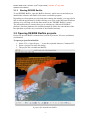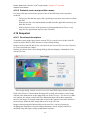
1
Institute for Energy Technology
Halden Virtual Reality Centre
Software User Manual
DESIRE RadVis Tool
ESA ESTEC Contract 17494/03/NL/LvH/jd
IFE Project O-8418
DRAFT – 15th July 2005
RadVis SUM Issue 1 Revision 4
30th August 2005
-i-
RadVis SUM Issue 1 Revision 4 (30th August 2005) – DRAFT 15th July 2005
Software User Manual
Abstract
This document is the software user manual for the DESIRE RadVis application.
It contains an overview of the system, a tutorial, and reference information for users
of RadVis.
This software manual is also available via the online help system in the RadVis
application.
ii- -
RadVis SUM Issue 1 Revision 4 (30th August 2005) – DRAFT 15th July 2005
Software User Manual
Document Status Sheet
Document Status Sheet
1. Document Title: Software User Manual
2. Document Reference Number: RadVis/SUM/doc
3. Issue
4. Revision
5. Date
6. Reason for change
1
0
2004.04.20
Document Issued
1
1
2004.05.01
Minor corrections
1
2
2004.11.22
Updated for Release 1.1
1
3
2005.06.24
Updated for Release 1.2
1
4
2005.mm.yy
Updated for Release 1.3
Issue 1 approved 20th April 2004
M. Louka, H. O. Randem
iii- -
RadVis SUM Issue 1 Revision 4 (30th August 2005) – DRAFT 15th July 2005
Software User Manual
Document Change Record
Document Change Record
DCR No.
1
Date
2005.06.24
Originator
M. N. Louka
Approved By
M. N. Louka
1. Document Title
Software User Manual
2. Document Reference Number
RadVis/SUM/doc/
3. Document issue / Revision Number
Issue 1/Revision 3
4. Page
5. Paragraph
6. Reason for change
i
-
Inserted IFE logo
II
-
rephrased
1
1.2
19
4.7.1
Increased version number of application item to 1.2
Clarified scale-by-value
iv- -
RadVis SUM Issue 1 Revision 4 (30th August 2005) – DRAFT 15th July 2005
Software User Manual
Contents
1
2
3
INTRODUCTION ........................................................................................... 1
1.1
INTENDED READERSHIP ................................................................................1
1.2
APPLICABILITY STATEMENT .........................................................................1
1.3
PURPOSE .....................................................................................................1
1.4
HOW TO USE THIS DOCUMENT ......................................................................1
1.5
RELATED DOCUMENTS .................................................................................1
1.6
CONVENTIONS .............................................................................................1
1.7
PROBLEM REPORTING INSTRUCTIONS ............................................................2
OVERVIEW .................................................................................................... 3
2.1
DESIRE AND DESIRE RADVIS...................................................................3
2.2
DESIRE RADVIS CAPABILITIES ...................................................................3
2.3
HARDWARE REQUIREMENTS .........................................................................4
2.4
PACKAGE CONTENTS ....................................................................................4
2.5
INPUT DATA .................................................................................................4
2.6
OVERVIEW OF THE USER INTERFACE .............................................................5
TUTORIAL ..................................................................................................... 6
3.1
4
GETTING STARTED .......................................................................................6
3.1.1
System requirements............................................................................6
3.1.2
Installation..........................................................................................6
3.1.3
Starting DESIRE RadVis .....................................................................7
3.2
OPENING DESIRE RADVIS PROJECTS ..........................................................7
3.3
NAVIGATING IN THE 3D VIEW ......................................................................8
3.4
SELECTING VISUALISATION MODE ................................................................9
3.4.1
Volume mode ......................................................................................9
3.4.2
Edges mode.......................................................................................10
3.4.3
Slice Mode ........................................................................................11
3.5
WORKING WITH THE VIRTUAL DOSIMETER .................................................12
3.6
SAVING IMAGES .........................................................................................13
REFERENCE .................................................................................................14
4.1
OPENING RADVIS DESIRE PROJECT FILES ................................................14
4.1.1
Functional description ......................................................................14
4.1.2
Cautions and warnings......................................................................14
4.1.3
Procedures........................................................................................14
v- -
RadVis SUM Issue 1 Revision 4 (30th August 2005) – DRAFT 15th July 2005
Software User Manual
4.1.4
What results to expect .......................................................................14
4.1.5
Probable errors and possible causes .................................................14
4.2
REPLACE MODEL .......................................................................................14
4.2.1
Functional description ......................................................................14
4.2.2
Cautions and warnings......................................................................14
4.2.3
Procedures........................................................................................15
4.2.4
What results to expect .......................................................................15
4.2.5
Probable errors and possible causes .................................................15
4.3
NAVIGATION .............................................................................................15
4.3.1
Functional Description .....................................................................15
4.3.2
Cautions and warnings......................................................................15
4.3.3
Procedures........................................................................................15
4.3.4
Probable errors and possible causes .................................................16
4.4
VIEWPOINTS ..............................................................................................16
4.4.1
Functional description ......................................................................16
4.4.2
Cautions and warnings......................................................................16
4.4.3
Procedures........................................................................................16
4.4.4
What results to expect .......................................................................16
4.4.5
Probable errors and possible causes .................................................16
4.5
SELECTING DATASETS TO VISUALISE...........................................................17
4.5.1
Functional Description .....................................................................17
4.5.2
Cautions and warnings......................................................................17
4.5.3
Procedures........................................................................................17
4.5.4
Probable errors and possible causes .................................................17
4.6
VISUALISATION MODES ..............................................................................17
4.6.1
Functional description ......................................................................17
4.6.2
Cautions and warnings......................................................................17
4.6.3
Procedures........................................................................................18
4.6.4
Probable errors and possible causes .................................................18
4.7
VOLUME VISUALISATION OPTIONS ..............................................................18
4.7.1
Functional description ......................................................................18
4.7.2
Cautions and warnings......................................................................20
4.7.3
Procedures........................................................................................20
4.7.4
Probable errors and possible causes .................................................20
4.8
SLICE VISUALISATION OPTIONS...................................................................20
vi- -
RadVis SUM Issue 1 Revision 4 (30th August 2005) – DRAFT 15th July 2005
Software User Manual
4.8.1
Functional description ......................................................................20
4.8.2
Cautions and warnings......................................................................21
4.8.3
Procedures........................................................................................21
4.9
SLICE VISUALISATION CONTROL .................................................................21
4.9.1
Functionality description ..................................................................21
4.9.2
Cautions and warnings......................................................................21
4.9.3
Procedures........................................................................................22
4.10
CONFIGURING THE COLOUR RANGE ...........................................................22
4.10.1
Functionality description ..................................................................22
4.10.2
Cautions and warnings......................................................................23
4.10.3
Procedure .........................................................................................23
4.10.4
Probable errors and possible causes .................................................23
4.11
PREFERENCES ............................................................................................23
4.11.1
Functional description ......................................................................23
4.11.2
Cautions and warnings......................................................................25
4.11.3
Procedures........................................................................................26
4.11.4
Probable errors and possible causes .................................................26
4.12
HEADLIGHT ...............................................................................................26
4.12.1
Functional description ......................................................................26
4.12.2
Cautions and warnings......................................................................26
4.12.3
Procedures........................................................................................26
4.12.4
What results to expect .......................................................................26
4.12.5
Probable errors and possible causes .................................................26
4.13
VIRTUAL DOSIMETER ................................................................................26
4.13.1
Functional Description .....................................................................26
4.13.2
Cautions and warnings......................................................................27
4.13.3
Procedure .........................................................................................27
4.13.4
What results to expect .......................................................................28
4.13.5
Probable errors and possible causes .................................................28
4.14
HEAD-UP DISPLAY ....................................................................................28
4.14.1
Functional description ......................................................................28
4.14.2
Cautions and warnings......................................................................30
4.14.3
Procedures........................................................................................30
4.14.4
Probable errors and possible causes .................................................30
4.15
PROJECT CHOOSER ....................................................................................30
vii- -
RadVis SUM Issue 1 Revision 4 (30th August 2005) – DRAFT 15th July 2005
Software User Manual
4.15.1
Functional description ......................................................................30
4.15.2
Cautions and warnings......................................................................31
4.15.3
Procedures........................................................................................31
4.15.4
What results to expect .......................................................................32
4.15.5
Probable errors and possible causes .................................................33
4.16
SNAPSHOT .................................................................................................33
4.16.1
Functional description ......................................................................33
4.16.2
Cautions and warnings......................................................................34
4.16.3
Procedures........................................................................................35
4.16.4
What results to expect .......................................................................35
4.16.5
Probable errors and possible causes .................................................35
4.17
DISPLAY CONFIGURATION ..........................................................................36
4.17.1
Functional description ......................................................................36
4.17.2
Cautions and warnings......................................................................37
4.17.3
Procedures........................................................................................37
4.17.4
What results to expect .......................................................................37
4.17.5
Probable errors and possible causes .................................................37
4.18
TOGGLE GEOMETRY REPRESENTATION........................................................37
4.18.1
Functional description ......................................................................37
4.18.2
Cautions and warnings......................................................................38
4.18.3
Procedures........................................................................................38
4.18.4
What results to expect .......................................................................38
4.18.5
Probable errors and possible causes .................................................38
4.19
TOGGLE BACKGROUND SCENE ....................................................................38
4.19.1
Functional description ......................................................................38
4.19.2
Cautions and warnings......................................................................38
4.19.3
Procedures........................................................................................38
4.19.4
What results to expect .......................................................................38
4.19.5
Probable errors and possible causes .................................................38
4.20
DOSE CALCULATION ..................................................................................39
4.20.1
Functional description ......................................................................39
4.20.2
Cautions and warnings......................................................................40
4.21
INTERPOLATION .........................................................................................40
4.21.1
Functional description ......................................................................40
4.21.2
Cautions and warnings......................................................................40
- viii
RadVis SUM Issue 1 Revision 4 (30th August 2005) – DRAFT 15th July 2005
Software User Manual
4.21.3
Procedures........................................................................................40
4.21.4
What results to expect .......................................................................40
4.21.5
Probable errors and possible causes .................................................40
4.22
4.22.1
Functional description ......................................................................40
4.22.2
Cautions and warnings......................................................................40
4.22.3
Procedures........................................................................................41
4.22.4
What results to expect .......................................................................41
4.22.5
Probable errors and possible causes .................................................41
4.23
STARTING UP FROM A COMMAND-LINE .......................................................41
4.23.1
Functional description ......................................................................41
4.23.2
Cautions and warnings......................................................................41
4.23.3
Procedures........................................................................................41
4.23.4
What results to expect .......................................................................42
4.23.5
Probable errors and possible causes .................................................42
4.24
ONLINE HELP ............................................................................................43
4.24.1
Functional description ......................................................................43
4.24.2
Cautions and warnings......................................................................43
4.24.3
Procedures........................................................................................43
4.24.4
What results to expect .......................................................................43
4.24.5
Probable errors and possible causes .................................................43
4.25
5
ERROR MARGINS .......................................................................................40
MENUS ......................................................................................................44
4.25.1
File Menu..........................................................................................44
4.25.2
Edit Menu .........................................................................................44
4.25.3
View Menu ........................................................................................45
4.25.4
Tools Menu .......................................................................................46
4.25.5
Type Menu ........................................................................................46
4.25.6
Help Menu ........................................................................................46
APPENDIX .....................................................................................................48
5.1
GLOSSARY.................................................................................................48
5.2
DESIRE RADVIS PROJECT FILE FORMAT ...................................................49
5.2.1
Overview and Example......................................................................49
5.2.2
Explanation of each XML element.....................................................49
ix- -
RadVis SUM Issue 1 Revision 4 (30th August 2005) – DRAFT 15th July 2005
Software User Manual
1 Introduction
1.1 Intended readership
The audience for the software user manual is the users of the DESIRE RadVis
software.
Anticipated users include space engineers, scientists, and doctors interested in rapid
assessment and visualisation of radiation flux or dose levels as a function of position
inside the ESA Columbus module.
1.2 Applicability statement
This issue of the Software User Manual applies to Version 1.3 of the DESIRE RadVis
software.
1.3 Purpose
DESIRE RadVis is used to visualize the result of DESIRE radiation predictions for
the ISS Columbus module in an interactive 3D virtual environment, providing a rapid,
easily comprehensible, visual overview of the results.
This document is the software user manual for the DESIRE RadVis software. The
Software manual is also available via an online help system. It introduces the software
and its intended usage, and provides useful reference material for advanced users.
1.4 How to use this document
This document should be used as a guide to the application and use of the software.
It is intended to provide a general understanding of the capabilities of RadVis and
how these capabilities can be accessed.
The overview section describes the processes and principles supported by the
software and how it intended to be used.
The tutorial section is intended to assist users in getting started with software, and
perform the most commonly performed task using the software.
The reference section provides comprehensive information about all the software
capabilities.
1.5 Related documents
ISO/IEC 14772-1
Virtual Reality Modelling Language Specification, 1997.
Available online on the Web3D Consortium website at
http://www.web3d.org/.
1.6 Conventions
File paths and contents of data files are shown using the Courier font. e.g.
c:/radvis/geometry/iss/iss.wrl
The convention “Menu Name > Menu Item” is used to indicate a menu selection from
the application’s main menu bar.
Keyboard shortcuts are described as “Command-<Key>” e.g. “Command-X”.
1- -
RadVis SUM Issue 1 Revision 4 (30th August 2005) – DRAFT 15th July 2005
Software User Manual
The command key that should be used for keyboard shortcuts depends on the host
platforms used. For example, for most platforms it is the control key, however on Mac
OS X it is the Apple/command key. Some platforms use the alt key as a command
key. The correct key for keyboard shortcuts is always indicated in the applications
menus on the platform on which it is run.
Distance units are in metres.
The Y-axis is up in the 3D coordinate system used by RadVis.
1.7 Problem reporting instructions
Please send questions, bug reports, or requests for new features to: [email protected]
When submitting bug reports, please include the following information:
•
A description of the result and how it differed from what you expected.
•
The conditions or circumstances under which the problem occurred.
•
Any other information that could be useful to isolate the problem.
2- -
RadVis SUM Issue 1 Revision 4 (30th August 2005) – DRAFT 15th July 2005
Software User Manual
2 Overview
2.1 DESIRE and DESIRE RadVis
The European Space Agency’s DESIRE project aims at accurate predictions of
radiation fluxes inside the Columbus module of the ISS.
DESIRE RadVis is an independent software tool that is intended primarily for
visualising the results of DESIRE radiation predictions for the ISS Columbus module
in an interactive 3D virtual environment, to provide a rapid, easily comprehensible,
visual overview of the results.
DESIRE RadVis presents the user with an interactive three-dimensional virtual
environment that combines a visually realistic model of the Columbus module with
3D visualisation of radiation flux and dose levels in and around the module.
All radiation flux and dose data that can be visualised using the tools are created by
the DESIRE project. The DESIRE RadVis software does not make predictions about
radiation flux or dose itself, with the exception of the calculation of total effective
dose, based on input data from DESIRE.
2.2 DESIRE RadVis capabilities
The purpose of DESIRE RadVis is to present predictions created by the DESIRE
project in a rapid and easily compressible manner and to enhance the radiation
awareness of astronauts and ground personnel at ESA.
The software installation includes 3D geometry of the ISS Columbus module with
sufficient detail that significant components can be visually identified.
After opening project files created by DESIRE, the user is able to freely navigate in a
virtual environment to view the Columbus module, overlaid with 3D visualisation of
radiation flux or dose levels, from any angle.
The user is able to visualise γ, α, β-radiation, protons, neutrons, ionising particles and
flux, both as individual radiation species and as combined total effective dose rate.
The visualisation includes the display of properties relevant to the radiation species
shown.
The user is able to control the 3D radiation visualisation, selecting between alternative
visualisation strategies including colour planes and volumetric plots with direction
vectors shown when direction data is available.
A virtual dosimeter is available to the user at all times to display the value of the
absorbed dose (Gy/h), dose-rate (mSv/h) or flux, depending on which radiation specie
is being considered, at the user’s current position.
The user can query any location within the radiation data range supplied by DESIRE
to view virtual dosimeter values for that location.
The user is able to save snapshots of the virtual environment to the local file system.
These snapshots can be used to illustrate reports and presentations.
3- -
RadVis SUM Issue 1 Revision 4 (30th August 2005) – DRAFT 15th July 2005
Software User Manual
2.3 Hardware requirements
Users will typically operate the software on a desktop personal computer with a single
display device however the software will also be able to function in environments
where multi-screen display systems are used.
DESIRE RadVis can be installed on any computer that meets the minimum hardware
and operating system requirements.
As the software makes extensive use of interactive 3D graphics, the host computer
must have hardware-accelerated graphics capabilities in order to run the software
efficiently. The standard input devices supported by the software are keyboard and
mouse. A mouse with three buttons is recommended for optimal ease of user
interaction with the 3D environment, however a two-button mouse is sufficient to
operate the software.
2.4 Package contents
The DESIRE RadVis software package consists of a 3D viewer application with
radiation visualisation functionality, and a 3D geometry model of the ISS Columbus
module. Some additional configuration files are also included, and are intended for
advanced users. An example project file and a “Read Me” are also included among
the file installed by the installation program.
2.5 Input data
Input data for DESIRE RadVis is normally provided in the form of data exported
from the DESIRE system. Data is transferred between the systems in the form
DESIRE RadVis project files.
Note that while the system will, by default, use ISS Columbus geometry, it is possible
to load geometry for other vessels, buildings or components (for example, exported
from Geant4). In such a case, the radiation predictions loaded into the system should
be relevant to the geometry and will not necessarily need to come from DESIRE as
long as the data is formatted correctly for RadVis.
DESIRE
DESIRE RadVis Project Files
(Radiation predictions)
3D Geometry
Columbus
Geometry
Visual
information
DESIRE
RadVis
User
actions
User
The relationship between DESIRE, DESIRE RadVis and the User
4- -
RadVis SUM Issue 1 Revision 4 (30th August 2005) – DRAFT 15th July 2005
Software User Manual
2.6 Overview of the user interface
The DESIRE RadVis User Interface
The RadVis user interface consists of a window title bar, a main menu bar with
menus, a 3D view, and a toolbar.
In the example above, a project file has been opened and a model of the ISS
Columbus module is displayed in the 3D view with “Edge” visualisation of proton
energy data activated.
An overview of the colour range used for the visualisation and a virtual dosimeter are
displayed in a head-up display in the 3D view. The virtual dosimeter is not showing a
location-based value in this example, as the camera is outside the area of the dataset.
Note that the appearance of some user interface elements vary depending on the host
operating system, but the general layout and functionality is the same for all
platforms.
5- -
RadVis SUM Issue 1 Revision 4 (30th August 2005) – DRAFT 15th July 2005
Software User Manual
3 Tutorial
3.1 Getting started
3.1.1
System requirements
The DESIRE RadVis is based on cross-platform Java technology.
If you are using Microsoft Windows or Linux x86 then the installer will offer to
install an appropriate Java environment for you. The software can be installed on
other operating systems that supports the minimum required Java 2 and Java 3D
software versions listed below.
If you are not using Microsoft Windows or Linux, ensure that Java and Java 3D are
installed before installing the DESIRE RadVis. The latest versions of Java and Java
3D can be located on Sun Microsystems' Java Web site at <http://java.sun.com/> and
<http://java.sun.com/products/java-media/3D/>.
The minimum recommended requirements for the system is:
•
•
•
•
•
•
•
1800 MHz Pentium 4 Personal Computer
512MB RAM
Microsoft Windows 2000/XP
Java 2 JRE/JDK 1.4.2
Java 3D 1.3.1 (OpenGL or Direct3D version, depending on the system's
graphics accelerator)
3D Graphics accelerator card with either OpenGL or Direct3D support
A three-button mouse
The software can be used on a less powerful hardware configuration with a twobutton mouse, however system performance will not be optimal. Use the alt-key on
your keyboard in combination with the left mouse button to simulate the middle
mouse button if you do not have a three-button mouse. For single-button mice, the
control key is typically used in conjunction with a mouse click to simulate a rightbutton click.
Note that the Direct3D version of Java 3D is not compatible with Windows NT 3.x or
4.x. Please use the OpenGL version of Java 3D if you are using Windows NT.
The software is bundled with the OpenGL version of Java 3D. Computers, in
particular laptop computers, with limited 3D graphics support often perform better
with the Direct3D version of Java 3D, which can be downloaded from Sun
Microsystem’s website (address provided above). Note that the Direct3D version is
only available for computers running Microsoft Windows. Linux and Mac OS X
users, for example, should use the bundled OpenGL version of Java 3D.
3.1.2
Installation
Important: See System Requirements above before installing.
The installer called “RadVis Installer” installs the RadVis application and supporting
files.
Double-click on the installer and follow the instructions.
6- -
RadVis SUM Issue 1 Revision 4 (30th August 2005) – DRAFT 15th July 2005
Software User Manual
3.1.3
Starting DESIRE RadVis
To run DESIRE RadVis, open the RadVis directory, which was created when you
installed the software and double-click on the executable program.
Depending on what options you selected when running the installer, you may also be
able to start the application by double clicking on an icon on the Microsoft Windows
desktop or by selecting it from the Start menu (in the "DESIRE RadVis" group).
The information above assumes that you are running on a Microsoft Windows
platform. On other platforms, the installer attempts to follow the conventions of the
host platform to provide easy execution of the installed software.
3.2 Opening DESIRE RadVis projects
Project file provide RadVis with the data it needs to present a 3D scene and dataset
visualisation.
To open a project file in RadVis:
1. Select “File > Open Project…” or use the keyboard shortcut “Command-O”.
2. Select a project file in the file dialog.
3. The project file is loaded into RadVis.
A project file loaded into RadVis
7- -
RadVis SUM Issue 1 Revision 4 (30th August 2005) – DRAFT 15th July 2005
Software User Manual
3.3 Navigating in the 3D view
There are two ways of navigating in RadVis: fly and examine.
Fly navigation enables you to freely navigate in the 3D view and to inspect the loaded
geometry and 3D data visualisation from any angle and location
Examine navigation enables you to rotate the viewpoint around the centre of the
loaded geometry to examine the scene.
The default navigation mode in RadVis is fly navigation.
To use fly navigation:
Drag the mouse in the 3D scene.
If you have a three-button mouse, the navigation behaviours are assigned like this:
•
•
•
Fly - Left mouse button
Tilt - Middle mouse button
Pan - Right mouse button
Use the alt-key on your keyboard in combination with the left mouse button to
simulate the middle mouse button if you do not have a three-button mouse. For
single-button mice, the control key is typically used in conjunction with a mouse click
to simulate a right-button click.
It is also possible to use assign fly navigation mode mouse behaviour to the left button
by using the navigation buttons to select mouse behaviour.
The navigation buttons
To use examine navigation:
1. Select the Examine button (see figure above).
2. Drag the mouse in 3D scene to examine the scene.
3. Select the examine button again to disable the examine mode, and return to fly
mode.
8- -
RadVis SUM Issue 1 Revision 4 (30th August 2005) – DRAFT 15th July 2005
Software User Manual
3.4 Selecting visualisation mode
You can choose between volume, edges and slice visualisation strategies for
visualising a dataset.
3.4.1
Volume mode
To use the Volume visualisation mode:
1. Select “View>Volume” or use the keyboard shortcut “Command-L”. Selecting
the Volume button also toggles the volume visualisation mode.
Volume button
RadVis with Volume visualisation mode active
9- -
RadVis SUM Issue 1 Revision 4 (30th August 2005) – DRAFT 15th July 2005
Software User Manual
3.4.2
Edges mode
To use the Edges visualisation mode:
1. Select “View> Edges” or use the keyboard shortcut “Command-E”. Selecting
the Edges button can also toggle the edges mode.
Edges button
RadVis with Edges visualisation mode active
10- -
RadVis SUM Issue 1 Revision 4 (30th August 2005) – DRAFT 15th July 2005
Software User Manual
3.4.3
Slice Mode
To use the Slice visualisation mode:
1. Select “View> Slice” or use the keyboard shortcut “Command-P”. Selecting
the Slice button can also toggle the slice mode.
Slice button
2. When in slice mode the buttons for moving the slice are enabled.
Buttons for moving slice
The two buttons to the left move the slice depending on which axis around
which the slice is moved.
The button to the right switches the axis the slice is moved along.
RadVis with Slice visualisation mode active
11- -
RadVis SUM Issue 1 Revision 4 (30th August 2005) – DRAFT 15th July 2005
Software User Manual
3.5 Working with the Virtual Dosimeter
The virtual dosimeter is used for querying specific points in the dataset.
To use the virtual dosimeter:
1. Select “Tools > Detached Dosimeter” or use the keyboard shortcut
“Command-D” to detach the dosimeter.
2. The virtual dosimeter is detached from your “body”, and appears in front of
the your view.
3. Select “View > Info” or use the keyboard shortcut “Command-I” to enable the
information head-up display (HUD).
4. Information about the current location of the virtual dosimeter is displayed in
the information HUD.
5. Using the mouse you can drag the virtual dosimeter around in the 3D scene.
If you click and drag the side of the dosimeter that is facing towards you, the
dosimeter will be moved to your left or right.
If you click and drag on the top or bottom of the dosimeter, it will be moved
up or down.
Note that the information HUD is updated when the dosimeter is moved.
RadVis with a detached Virtual Dosimeter and Information HUD enabled
12- -
RadVis SUM Issue 1 Revision 4 (30th August 2005) – DRAFT 15th July 2005
Software User Manual
3.6 Saving images
To save an image of the scene:
1. Select “File > Save Image…” or use the keyboard shortcut “Command-S”.
2. A dialog box with a thumbnail of the current 3D view will appear (see figure
below).
3. Select the required file format and image size.
4. Press the Save button.
5. Select the destination and filename for the image file in the file dialog box that
appears, and then press OK.
6. The image is saved to the chosen destination.
Save Image dialog
13- -
RadVis SUM Issue 1 Revision 4 (30th August 2005) – DRAFT 15th July 2005
Software User Manual
4 Reference
4.1 Opening RadVis DESIRE Project Files
4.1.1
Functional description
The main purpose of a project file is to supply RadVis with DESIRE data as input.
A project file is normally generated by DESIRE and contains all necessary data
needed to visualise datasets defined in the file.
RadVis is used to visualise datasets as well as 3D model geometry, 3D background
scenes, and other information also specified in the file.
4.1.2
Cautions and warnings
Only one project is active at any given moment.
4.1.3
Procedures
There are several ways of loading data in a project file into RadVis.
•
If the software is started from the command line (or via a script) with a project
file as a parameter, it will be initialised with the data defined in the supplied
project file.
•
Selecting the “File > Open Project…”, or using the keyboard shortcut
“Command-O”, causes a file dialog to appear. If a selected RadVis project file
is opened, then it will be loaded, replacing any previously loaded data.
•
Dragging a project file into the 3D view, and dropping it. Previously loaded
project data is replaced.
4.1.4
What results to expect
The result of opening a project file should be a 3D scene with one or more datasets
available for visualisation.
4.1.5
Probable errors and possible causes
RadVis may run out of memory if the project file references very large VRML97
files. Please note that this is dependent on the amount of memory available on the
system RadVis is run on.
RadVis is only capable of loading project files in the XML format specified.
4.2 Replace Model
4.2.1
Functional description
It is possible to replace a loaded model with an alternative model without resorting to
modifying a project file. The currently displayed in the scene geometry is by the new
geometry selected by the user.
4.2.2
Cautions and warnings
RadVis supports geometry files in the ISO VRML97 format only.
14- -
RadVis SUM Issue 1 Revision 4 (30th August 2005) – DRAFT 15th July 2005
Software User Manual
Support for VRML behaviours is limited. VRML files with dynamic content are not
recommended. In particular, animated objects are not usually appropriate in the
context of this software. Interactive VRML behaviour defined in VRML files is
ignored.
4.2.3
Procedures
To replace a model:
1. Select the “File > Replace Model...” menu item
2. A file dialog will appear, select the VRML file to load.
3. The mode in the selected file should appear after a brief pause while the file is
loaded.
4.2.4
What results to expect
Any previously loaded geometry should be replaced with the chosen model.
4.2.5
Probable errors and possible causes
If problems with loading VRML 97 files occur, one of the following errors may be
the cause:
•
If a large file is opened, the application may run out of memory. If that
happens, the application may “hang” in some cases.
•
RadVis is only capable of loading files in the ISO VRML97 format. The
current version of RadVis does not support 3D files.
•
Support for VRML97 behaviours is limited. The results may not be as
expected if a VRML file is loaded that contains dynamic content that depends
on scripts to generate geometry, for example.
4.3 Navigation
4.3.1
Functional Description
The user is able to freely navigate in a virtual environment to view loaded 3D
geometry and data visualisation from any location and direction. The user is also able
to rotate the entire scene to examine it.
4.3.2
Cautions and warnings
None
4.3.3
Procedures
There are two main types of navigation in RadVis, examine and fly navigation. While
the examine navigation modifies the transform to the geometry, the fly navigation
modifies the viewpoint to the user.
4.3.3.1
Examine Navigation
Press the Examine button to activate it. Using the left mouse button the scene can now
rotated in the mouse movement direction. The centre of rotation coincides with the
centre of the scene geometry. Other navigation modes is not accessible when the
examine buttons is pressed.
15- -
RadVis SUM Issue 1 Revision 4 (30th August 2005) – DRAFT 15th July 2005
Software User Manual
4.3.3.2
Fly Navigation
The mouse is used to move around in relation to the 3D scene.
If a three-button mouse is used, the buttons are mapped as follows:
•
•
•
Fly - Left mouse button
Tilt - Middle mouse button
Pan - Right mouse button
If a two-button mouse is used, it is possible to tilt the virtual camera by holding down
the alt-key while dragging the mouse with the right mouse button pressed.
It is also possible to select the different navigation modes by pressing one of the
buttons shown in the picture below.
Pressing one of the "Fly", "Tilt", "Pan", or “Examine buttons activates the selected
navigation mode. This temporarily assigns the selected navigation mode to the left
mouse button. The active navigation mode is highlighted.
4.3.4
Probable errors and possible causes
None.
4.4 Viewpoints
4.4.1
Functional description
Viewpoints are fixed locations from which the model geometry can be viewed to
facilitate navigation in the 3D scene.
Radvis provides predefined viewpoints for Front, Back, Left, Right, Top and Bottom.
Viewpoint transitions are animated to prevent disorientation when moving to a new
location in the scene.
4.4.2
Cautions and warnings
None.
4.4.3
Procedures
To move to a predefined viewpoint:
•
Select one of the predefined viewpoints in the viewpoints drop-down menu to
the far left of the RadVis toolbar.
•
Alternatively, click on the arrow buttons next to the viewpoint drop-down
menu to cycle through the viewpoints.
4.4.4
What results to expect
A smooth transition from the current viewpoint to the selected viewpoint.
4.4.5
Probable errors and possible causes
None.
16- -
RadVis SUM Issue 1 Revision 4 (30th August 2005) – DRAFT 15th July 2005
Software User Manual
4.5 Selecting datasets to visualise
4.5.1
Functional Description
A project file can contain one or more datasets. You can select which dataset to
visualise via the “Type” menu.
When a project file is loaded, the “Type” menu is updated and menu items for the
datasets included in the project are enabled.
4.5.2
Cautions and warnings
None.
4.5.3
Procedures
To make a data set active:
Select “Type” and choose the dataset to be visualised from the menu/sub-menus.
Tip: Pressing the left mouse button while holding down the SHIFT key will also open
the “Type” menu.
4.5.4
Probable errors and possible causes
If a project fails to load then the “Type” menu will not be enabled until a valid project
is opened.
4.6 Visualisation modes
4.6.1
Functional description
There are three main data visualisation modes in RadVis: Volume, Edges and Slice.
In the Volume visualisation mode, the value of each area in the underlying data grid
is visualized as a coloured box or a directional arrow. The colour is determined by the
value of the area. The colour is configured by the Colour Range Settings (see 4.10) ,
where ranges of values are mapped to colours.
The Edges visualisation mode displays boundaries between neighbouring areas that
are mapped to different colours. The boundaries are constructed of transparent
surfaces assigned the colour represented by the highest range. i.e. if the colour yellow
represents values between 3 and 5, and red represents values between 5 and 8, there
will be a red surface between neighbour areas containing red and yellow values.
The Slice visualisation mode displays a plane of values, where the plane is
perpendicular to the X, Y, or Z-axis. The plot can be visualised in several ways (see
4.8)
4.6.2
Cautions and warnings
For run-time optimization reasons, the geometry of the different visualization modes
are calculated and created when they are selected. When the visualisation mode is
switched to Volume, for large data sets, it may take a few seconds for the
visualisation to be generated.
In Edges mode, nothing will be drawn if all data falls within the same colour range
band.
17- -
RadVis SUM Issue 1 Revision 4 (30th August 2005) – DRAFT 15th July 2005
Software User Manual
4.6.3
Procedures
To choose the Volume visualisation mode:
•
Select “View > Volume”
•
Press the Volume button on the toolbar, or use the keyboard shortcut “CommandL”
To choose the Edge visualisation mode:
•
Select “View > Edges”
•
Press the Edges button on the toolbar, or use the keyboard shortcut “Command-E”
To choose the Slice visualisation mode:
•
Select “View > Slice”
•
Press the Slice button on the toolbar, or use the keyboard shortcut “Command-P”
4.6.4
Probable errors and possible causes
In a low memory situation, switching to Volume visualisation could result in an out of
memory situation.
4.7 Volume visualisation options
4.7.1
Functional description
The Volume options can be changed in the Volume tab in the View Options dialog,
which can be opened by selecting “View > Options…”.
Volume options
Geometry:
The geometry of a dataset is determined when the dataset is loaded. Directional
datasets gets are visualised with arrows and non-directional are visualised with boxes.
It is possible to visualise a directional data set as non-directional by selection boxes
instead of arrows. If arrows are selected for a non-directional dataset, the lack of
directional information will cause all arrows to point upwards (positive Y-direction).
18- -
RadVis SUM Issue 1 Revision 4 (30th August 2005) – DRAFT 15th July 2005
Software User Manual
19- -
RadVis SUM Issue 1 Revision 4 (30th August 2005) – DRAFT 15th July 2005
Software User Manual
LOD Distance:
To prevent visual cluttering of data values displayed simultaneously on the screen,
groups of eight values in the underlying data grid are successively combined based on
a user-specified distance, called the level-of-detail (LOD) distance. For example, if
the LOD distance value is 5m then the amount of data shown is reduced every 5m
from the user so that more detail for points closer to the user than further away.
The geometric representation of the combined data value for a given location is larger
(if the Scale by Value option is not set), reflecting the area of the grid for which it
represents data. The combined value and direction are calculated using the mean
values of the combined values.
Increasing the LOD distance gives greater visual detail in the scene, but may result in
slower 3D rendering performance and a poorer visual overview of the dataset,
decreasing the usability of the software.
Scale by Value:
By default, the geometric representation of values is the same size for all value in the
grid. If “Scale by Value” is selected, the size of the geometry is also affected by the
value at the grid area represented. The lower the value, the smaller the geometry
within the area of the grid it represents.
4.7.2
Cautions and warnings
None.
4.7.3
Procedures
To modify volume options:
1.
2.
3.
4.
4.7.4
Select “View > Options…” to open the View Options dialog.
The Volume tab is selected by default.
Change parameters to the preferred settings
a)
Press Apply to use the new settings without closing the dialog
b)
Press OK to use the new settings and close dialog
c)
Press Cancel to close the dialog without saving settings
Probable errors and possible causes
An error message is displayed if a non-numeric value is entered into the LOD distance
field.
4.8 Slice visualisation options
4.8.1
Functional description
The Slice options can be changed in the Slice tab in the View Options dialog, which
can be opened by selecting “View > Options…”
20- -
RadVis SUM Issue 1 Revision 4 (30th August 2005) – DRAFT 15th July 2005
Software User Manual
Slice options
Rendering Style
The plot can be rendered as points, wire frame, as a (transparent) solid or as a
combination of transparent solid and wire frame.
Transparency
If a solid representation has been selected, the degree of transparency can be set here.
4.8.2
Cautions and warnings
None.
4.8.3
Procedures
To modify slice options:
1.
2.
3.
4.
Select “View > Options…” to open the View Options dialog.
Select the Slice tab
Change parameters to the preferred settings
a)
Press Apply to use the new settings without closing the dialog
b)
Press OK to use the new settings and close dialog
c)
Press Cancel to close the dialog without saving settings
4.9 Slice visualisation control
4.9.1
Functionality description
For investigating the whole volume, the slice plane can be moved along its
perpendicular axis. The perpendicular axis can also be toggled between the x, y and zaxis.
4.9.2
Cautions and warnings
None.
21- -
RadVis SUM Issue 1 Revision 4 (30th August 2005) – DRAFT 15th July 2005
Software User Manual
4.9.3
Procedures
To move a slice:
1. Ensure that Plot mode is selected.
2. Press the “Move Slice” buttons on the toolbar or use the shortcut keys
“Command-Left” and “Command-Right” to move the slice.
To change a slice’s perpendicular axis:
1. Ensure that Plot mode is selected.
2. Press the “Change Slice Axis” button on the toolbar or the shortcut key
“Command-A” to change the Slice axis.
4.10 Configuring the Colour Range
4.10.1 Functionality description
The colour ranges can be changed in the Colours tab in the View Options dialog.
Modifying a colour range only affects the representation of the active radiation
species and type (i.e. alpha, particles). i.e. Each radiation specie and type combination
has an individually configurable colour range to represent its values.
Colour Ranges
Limit
The parameter "Limit" indicates the highest value level to be taken into account.
Values higher than this are assigned the same colour as the limit value.
Auto
Enabling “Auto” will set the Limit to the highest value in the dataset.
Linear, exponential or logarithmic colour distribution
Based on the limit value and the number of colours added, a linear, exponential, or
logarithmic colour distribution between zero and the maximum value is created.
22- -
RadVis SUM Issue 1 Revision 4 (30th August 2005) – DRAFT 15th July 2005
Software User Manual
Changing colours
To change a colour, select the colour and press "Set Colour...". A colour dialog will
appear, and the desired colour can be selected.
Adding and removing colours
To add a colour, select the colour below where you want your new colour to appear
and press "Add". The new colour can be configured using "Set colour..." To delete a
colour, select the unwanted colour and press "Remove". Whenever the number of
colours is changed, the colour distribution is recalculated.
4.10.2 Cautions and warnings
None.
4.10.3 Procedure
To customise the colour range:
1.
2.
3.
4.
Select “View > Options…” to open the View Options dialog.
Select the Colours tab.
Change parameters to the preferred settings
a)
Press Apply to use the new settings without closing the dialog
b)
Press OK to use the new settings and close dialog
c)
Press Cancel to close the dialog without saving settings
4.10.4 Probable errors and possible causes
An error message is displayed if a non-numeric value is entered into the Limit field.
4.11 Preferences
4.11.1 Functional description
The Preferences dialog can be used to adjust the underlying data grid that loaded data
sets are mapped to, as defined in the project file.
The preferences are divided into two different parts: Dataset Preferences and Units
Preferences
The Dataset Preferences tab enables the grid dimensions and resolution to be adjusted
and specified whether RadVis should interpolate data automatically, to fit the grid,
when loading project files.
The Unit Preferences tab enables the user to specify units for the different radiation
species.
23- -
RadVis SUM Issue 1 Revision 4 (30th August 2005) – DRAFT 15th July 2005
Software User Manual
4.11.1.1 Dataset Preferences
Preferences dialog with Dataset tab active
The Grid Dimension drop down box contains all available grid dimensions the user
can choose between. The dimension decides how many points containing radiation
data we have in the x, y and z direction.
Note that selecting a high grid resolution will impact the performance of the software.
The Grid Resolution (m) decides the space between each point in meters. This helps
the user configure the size of the visualisation. A grid resolution of 1.0 meter
combined with grid dimension 16x16x16 will create a radiation visualisation of 16m
in length in each of the x, y and z directions.
The “interpolate on Load” check box specifies if the dataset should be interpolated or
not when a project file is loaded into RadVis.
24- -
RadVis SUM Issue 1 Revision 4 (30th August 2005) – DRAFT 15th July 2005
Software User Manual
4.11.1.2 Units Preferences
Preferences dialog with the Units tab active
The Units tab is used to specify the unit the different radiation species should be
presented in.
Each drop-down menu represents a unit for radiation species.
Explanation of unit abbreviations
The following abbreviations apply to all species (except energy):
s
seconds
m
minutes
h
hour
y
year
Energy:
Can only choose MeV (Mega electron Volt)
Particles:
Can choose between N (number) within different timeframes.
Dose:
Can choose between Gy (Grays) in (µ) micro, (m) milli and
Grays within different timeframes.
Equivalent Dose:
Can choose between Sv (Sievert) in (µ) micro and (m) milli with
different timeframes.
4.11.2 Cautions and warnings
The physical size of the grid is the grid resolution times the dimension of the grid.
When a lower grid resolution is chosen, some values in the original dataset may fall
outside the grid.
25- -
RadVis SUM Issue 1 Revision 4 (30th August 2005) – DRAFT 15th July 2005
Software User Manual
Note that preferences are not stored. In general, their purpose is to enable you to
override the default values in the project file.
4.11.3 Procedures
To access the preferences dialog:
•
Select “Edit>Preferences…” to access the Preferences dialog.
Refer to the functional description above for information about the meaning of the
various options.
After making your choices, press “OK” to apply them and close the Preferences
dialog, “Apply” to apply them without closing the Preferences dialog, or “Cancel” to
close the dialog without applying any of the changes that have been made.
4.11.4 Probable errors and possible causes
An error message is displayed if a non-numeric value is entered into the Grid
Resolution field of the Dataset preferences.
4.12 Headlight
4.12.1 Functional description
The Headlight aims a directional light in the direction the user is looking. This can be
useful if the loaded geometry contains no lights or is too dark.
4.12.2 Cautions and warnings
If the loaded geometry already contains light, the scene can appear too bright.
4.12.3 Procedures
To turn on the headlight:
•
Select “Tools > Headlight”, or use the shortcut key “Command-H”.
4.12.4 What results to expect
The scene is lit with additional light.
4.12.5 Probable errors and possible causes
None.
4.13 Virtual Dosimeter
4.13.1 Functional Description
The Virtual Dosimeter is used to display a location-dependent value from the active
dataset. The Virtual Dosimeter is by default attached to the 3D view (the user
“body”), but can be detached to query specific locations. The value at the Virtual
Dosimeter’s location is shown in the Information HUD.
The virtual dosimeter displays information about directional data in the dataset. The
directions are visualised with a cone inside the virtual dosimeter. The cone points in
the direction at current the position of the virtual dosimeter. If no directions are added
in the current set, the virtual dosimeter will display that as a box.
26- -
RadVis SUM Issue 1 Revision 4 (30th August 2005) – DRAFT 15th July 2005
Software User Manual
The virtual dosimeter changes colours according to the values defined in the Colour
Range and the value at the current location of the dosimeter. Thus, you can easily
check the approximate dose-rate at the current position of the virtual dosimeter. The
exact dose-rate value is displayed in the Head- Up Display.
Note that although the dosimeter is primarily intended for displaying dose-rates, it
actually shows the value of whatever dataset is current, with its unit. Therefore,
although this section of the user manual uses the term dose-rate to describe the value
shown, it may in fact be a different type of value, such as an energy level.
4.13.2 Cautions and warnings
The Information HUD must be visible in order to see the value at the Virtual
Dosimeter location.
4.13.3 Procedure
The virtual dosimeter can be detached from the “body” (at the location of the 3D view
camera). Doing this enables you to query specific locations in scene.
To detach the dosimeter from body:
1. Select “Tools>Detached Dosimeter”, or use the shortcut “Command-D”.
2. The virtual dosimeter is now visible in scene and ready to be moved.
3. In the information HUD the user can view the dose-rate, position, colour and
direction (if any) at the current locaiton of the virtual dosimeter.
The virtual dosimeter is by default attached to the body. When the virtual dosimeter is
attached to the body, all information about the current position is displayed in the
information HUD. In the information HUD the user can view the dose rate, position,
colour and direction (if any) to the current viewpoint.
To re-attach a detached dosimeter to the body:
1. Select “View > Detached Dosimeter”, or use the shortcut “Command-D”
To query arbitrary locations:
To move the Virtual Dosimeter to an arbitrary location, you need to detach it from the
body.
The movement of the Virtual Dosimeter depends on how you use the mouse and
select the virtual dosimeter.
To move the Virtual Dosimeter in the x, z direction:
1. Use the left mouse button and select the side on the virtual dosimeter that is
facing the view.
2. Dragging the mouse with the left mouse button down moves the dosimeter.
3. Dragging the mouse to left moves the dosimeter to the left.
4. Dragging the mouse to right moves the dosimeter to the right.
To move the Virtual Dosimeter in the y direction:
1. Use the left mouse button and select the top or bottom of the dosimeter.
2. Dragging the mouse with the left mouse button down moves the dosimeter.
27- -
RadVis SUM Issue 1 Revision 4 (30th August 2005) – DRAFT 15th July 2005
Software User Manual
3. Dragging the mouse downwards moves the dosimeter down.
4. Dragging the mouse up moves the dosimeter up.
4.13.4 What results to expect
When moving the Virtual Dosimeter, the cone inside the Virtual Dosimeter should
point in the direction the radiation has at that location. If the active dataset contains no
directional data, the Virtual Dosimeter displays a box.
When moving the dosimeter the colour of the cone or box will change according to
the colour configuration to indicate the dose rate at that point.
The Virtual Dosimeter in action
4.13.5 Probable errors and possible causes
None.
4.14 Head-Up Display
4.14.1 Functional description
The main purpose of the head-up display (HUD) is to provide the user with
information about the project file and current dataset. It also provides location-based
information from the view or Virtual Dosimeter. RadVis has two HUDs:
•
Information HUD: Displays information about the current project and scene.
•
Colour Range HUD: Displays the active colour configuration.
28- -
RadVis SUM Issue 1 Revision 4 (30th August 2005) – DRAFT 15th July 2005
Software User Manual
4.14.1.1 Information HUD Overview
The information HUD displays information about the project and scene.
Information HUD
1. Displays the currently active radiation specie.
2. Shows the direction of the radiation at the location of the Virtual Dosimeter.
The object can be either a cone or a box. If the object residing the HUD is a
box it indicates that the dataset we are using have no directions. If the object is
a cone it points in the direction of the radiation. The colour of the object will
change according to the colour configuration for the currently active data set.
3. Displays the value and unit at the location of the Virtual Dosimeter.
4. Displays the position of the Virtual Dosimeter. Please note that when the
dosimeter is attached to the body it displays the position of the view.
5. Displays the total equivalent dose at the front (F) and back (B) of the human
body. Please note that this information is only available when the total
effective dose dataset is selected.
6. Meta data information, displays the text string that is defined in the metadata
tag inside the RadVis project file.
4.14.1.2 Colour Range HUD Overview
The Colour Range HUD displays the current colour configuration used for this
dataset. See section 4.10 for details about how to adjust the colour configuration.
Colour Range HUD
29- -
RadVis SUM Issue 1 Revision 4 (30th August 2005) – DRAFT 15th July 2005
Software User Manual
The Colour Range HUD displays the currently used colour configuration with the
current user. The colour on the left side represents the value on the right side. In the
case above all radiation visualisation with the colour green has mean energy between
0.00 and 1.67e4. The Colour Range HUD is updated automatically if the colour
configuration changes.
4.14.2 Cautions and warnings
When resizing the window, the HUD may be end up located outside the view frustum
for some window aspect ratios.
The Information HUD will display the value “N/A” if no value exists at the current
location. This can occur if the data set is not interpolated or if the location is outside
the data set grid area.
4.14.3 Procedures
To display the Information HUD:
1. Select “View > Info”, or use the shortcut “Command-I”.
2. The information HUD appears at the top right corner of the window
To display the Colour Range HUD:
1. Select “View > Colour Ranges”, or use the shortcut “Command-J”.
2. The colour range HUD appears at the top left corner of the window.
3. To hide the colour range HUD press “View->Colour Ranges”, or press the
shortcut key command J again.
See section 4.10 for details about how to adjust the colour configuration.
4.14.4 Probable errors and possible causes
None.
4.15 Project Chooser
4.15.1 Functional description
The Project Chooser facility enables the user to easily access project files and browse
them in a user-configurable sequence. When switching to a new project file the
VRML model is not reloaded if it is already displayed in the scene.
Project Chooser Toolbar buttons with the Project List button highlighted
The Project List that the Project Chooser provides access to is used to add and remove
projects and to reorder them.
30- -
RadVis SUM Issue 1 Revision 4 (30th August 2005) – DRAFT 15th July 2005
Software User Manual
Project List Window
When you exit RadVis, the project list is stored. The next time RadVis starts up, the
list is automatically loaded into RadVis. The project list is a personal list so modify it
will not affect other uses of RadVis sharing your computer, unless they access it using
the same user account.
4.15.2 Cautions and warnings
If the volume rendering mode is selected, it may take a few seconds longer than other
rendering modes to switch between projects.
Only RadVis project files should be added to the Project List, other file types will fail
to load.
4.15.3 Procedures
To open the Project List
1. Press the “…” button in the project chooser in the RadVis toolbar
To add a project to the Project List:
1. Open the Project List
2. Press the “Add…” button
3. A file dialog box will appear.
31- -
RadVis SUM Issue 1 Revision 4 (30th August 2005) – DRAFT 15th July 2005
Software User Manual
4. Select a RadVis project file and press OK
5. Repeat the steps 1-3 to add more projects to the project list.
Please note that pressing the Cancel button located in the project window will not
undo your last changes to the project list, it will only close the project window.
To change the order of the projects:
1. Select the project that should change order.
2. Drag the selected project to the wanted position.
3. When added all desirable projects press the OK button at the bottom if the
project list window
To remove a added project from the project list:
1. Select the project that should be removed
2. Press the remove button at the top right corner of the project list window.
To browse projects:
Projects in the Project List can be loaded by selecting the required project file from
the drop down Project List, in which all the projects in the list are displayed.
You can alternatively pressing the “Previous Project” or “Next Project” buttons to
cycle through the projects in the list.
The Project Chooser enabled with all projects in Project List added.
•
The Project List menu shows the names of all projects in the Project List. The
name of the project currently loaded is displayed, when the menu is closed.In
the example above, the currently active project is called “radvis.xml”.
•
To load the next project in the Project List, press the “Next Project” button
(“<”).
•
To load the previous project in the Project List, press the “Previous Project”
button (“>”).
4.15.4 What results to expect
When switching project, a new set of datasets is loaded into RadVis. VRML files
referenced by the newly activated project are only loaded if project file referenced in
the replacement project file differ from those in the previously loaded project.
When switching project, you can expect a new scene with, if possible, the previously
active dataset type active in scene. Of course, the data visualised is that of the new
project. If the project file contains different models and different data sets types to
that of the previously active project then the effect will be similar to opening a new
project via the File menu.
32- -
RadVis SUM Issue 1 Revision 4 (30th August 2005) – DRAFT 15th July 2005
Software User Manual
4.15.5 Probable errors and possible causes
If a project file does not load as expected. One of the following errors may have
occurred.
-
The project file that the project list is pointing to may have been removed from
the disk.
-
If the project list is not automatically loaded when the application starts up, the
disk may be full.
-
If the reference to one of the geometry or background source files is a very
large file, the application may run out of memory.
4.16 Snapshot
4.16.1 Functional description
A snapshot raster image based on the current 3D view can be saved to the local file
system in either JPEG or PNG format via a Save Image dialog.
Images can be created at full-screen size (Screen), the current 3D view size (Current),
or a user-specified size (Other).
Options are chosen from a Save Image dialog, that also displays a thumbnail of the
current 3D view.
Save Image dialog with the current screen size and JPEG image format selected
If the selected size is Current then the image file created will contain a raster image
with the same dimensions as the image that was in the 3D view. For Screen or Other
size options, the image created will have dimensions that reflect those requested,
however the image is cropped rather than scaled to the required size and is therefore
not necessary identical to the image that was on in the 3D view.
Images created using this functionality can be used for a variety of purposes,
including the illustration of reports and presentations. Saved images can also be
modified using third-party image manipulation software.
33- -
RadVis SUM Issue 1 Revision 4 (30th August 2005) – DRAFT 15th July 2005
Software User Manual
4.16.2 Cautions and warnings
4.16.2.1 Image file formats
The PNG file format will often give better results than the JPEG format. JPEG
images, particularly small images, may exhibit artefacts resulting from the
compression process that are acceptable for the purpose of placing images on the
World-Wide Web or sending images as e-mail but may be of too poor quality for
publication in printed documents.
In general, it is recommended that the PNG file format be chosen to maximize the
quality of the saved image. If necessary, third-party image manipulation software can
then be used to convert original images to other formats or reduce their size.
4.16.2.2 System memory limitations
Saving images requires a significant amount of system memory, in particular to create
the snapshot of the 3D view. In low-memory situations, saving a snapshot may fail.
This is normally not an issue for images up to 1280 by 1024 pixels in size, on
computers that meet the minimum recommended system requirements, however very
detailed 3D models combined with a high-resolution display may result in insufficient
free memory for the save image functionality to operate. In situations where it is
known that the computer system is running at its limits, it would be appropriate to use
the “Other” size option to specify image sizes that will less likely exhaust the system
memory resources.
4.16.2.3 Image size restrictions
Although the Other size option permits the creation of images larger than the screen
size, this functionality is not supported by any known graphics card drivers. The
reason for this is that most drivers for 3D-acclerated graphics hardware restrict the
size of off-screen images (in this case a snapshot image) to the current screen size. In
this situation, the area outside the screen size will normally be black. A confirmation
dialog is displayed if a user requests an image larger than the screen size. If the user
selects No from this dialog, then the snapshot image created is scaled to fit within the
screen dimensions. Nevertheless, the ability to request images larger than the screen
size is supported as some systems (present or future) may support this. Note that this
means that to produce very high-resolution images, as high a screen resolution
possible on the computer system should be used, bearing in mind that very high
resolution images require a significant amount of memory to produce, as noted in the
previous paragraph).
4.16.2.4 Overwriting previously created image files
If the name of an existing file in an existing directory is entered in the Save dialog
then the existing file will be overwritten by the new file. This operation can fail if
permission to overwrite the file is not granted by the operating system.
4.16.2.5 File write-permissions
The image saving operation will fail if permission to write a file in the directory
chosen is not granted by the operating system. Images can only be written to
directories that the user has write-access to.
34- -
RadVis SUM Issue 1 Revision 4 (30th August 2005) – DRAFT 15th July 2005
Software User Manual
4.16.3 Procedures
To save a raster image snapshot of the current 3D view to the local file system:
1.
Select “File > Save Image…”.
2.
Choose the image size and image file format desired in the Save Image
dialog.
Image size options are full-screen size (Screen), the current 3D view size
(Current), or a user-specified size (Other):
If an Other size is chosen that exceeds the screen size, a confirmation dialog
is displayed. Large image sizes require significant amounts of memory to
produce, and images larger than the screen size may not be supported by the
graphics card or driver. Pressing “No” in the confirmation dialog results in
the image being scaled to within the Screen dimensions.
Image file format options are JPEG or PNG:
3.
Press “Save” to display a standard “save file” system dialog (or Cancel to
abort and close the Save Image dialog).
4.
Choose a location to save to and enter a filename in the Save dialog and
press “Save” to create and store an image file (or Cancel to return to the Save
Image dialog).
If a correct file extension is not entered, then the appropriate extension will
be appended for automatically (i.e. “.jpg” or “.png” will added to the file
name).
4.16.4 What results to expect
The usual result is a file in PNG or JPEG format.
The dimensions of the raster image stored in the file depend on the size options.
4.16.5 Probable errors and possible causes
The likely error is that no file is created. This is most likely the result of an out of
memory situation, which can occur if there are insufficient system resources available
to create an image of the required size. Although the software attempts to catch and
report and out of memory error, this is not always possible and so this error may not
be reported in all cases. Unless the amount of free memory is critically low, it is
normally possible to try again, in which case a smaller image size should be selected
in order to achieve a result.
Other situations where no file is created, but which are normally reported via an error
dialog, include if write-access is not granted by the host operating system to the
directory that the file was to be written to, and if an attempt is made to overwrite a
35- -
RadVis SUM Issue 1 Revision 4 (30th August 2005) – DRAFT 15th July 2005
Software User Manual
write-protected file. In the first case, a different directory should be chosen, for which
write-permission is available. In the second case, a different file name should be
entered.
Corrupt images, with either distortion, junk, or black areas are normally the result of
graphic card driver problems or restrictions. The image file itself is not corrupt –the
content of the file is visually incorrect. If the image size is “Other” and larger than the
screen size then the reason for the junk or black areas outside the upper left corner of
the image is that the graphics card/driver does not support images larger than the
current screen size. Other reasons for distortion or junk in images created include
bugs in the graphics card driver (in which case the problem can normally be solved by
updating to a newer driver) or, less likely, insufficient memory on the graphics card to
perform the operation successfully. In the second situation, an image creation failure
dialog would normally be displayed, as the graphics driver would report that it is
inability to perform the operation.
4.17 Display configuration
4.17.1 Functional description
RadVis can be used in different with different viewing configurations. The viewing
environment is based upon the contents of a configuration file. This allows RadVis to
run without change across a broad range of viewing configurations, such as windows
on conventional desktops, stereo-enabled views, full screen immersive displays on
single or multiple screens.
With RadVis it is distributed files for using RadVis is windowed mode, full screen
mode, windowed stereoscopic mode and a configuration for dual-screen (flat) desktop
configuration with no head tracking.
Changing to one of these modes requires that the application is restarted.
Full Screen mode
The full screen mode enlarges the scene so it covers the entire screen. The toolbar on
the bottom should be visible, but the application menu may not be visible.
The user must use keyboard shortcuts for using functionality that is placed in the
menu system.
Holding the shift key down while pressing the right mouse button in the application
window shows the type menu, and enables the user to switch dataset type even if we
have no menu system.
Stereoscopic mode
When using the stereo configuration file that is distributed with RadVis, the
application will start up in window mode. Please note that drawing stereoscopic
images require hardware that support rendering of stereoscopic images.
Dual-screen desktop configuration
Using this viewing configuration requires a dual screen desktop configuration, trying
to use this file on other equipment will cause RadVis to fail.
36- -
RadVis SUM Issue 1 Revision 4 (30th August 2005) – DRAFT 15th July 2005
Software User Manual
4.17.2 Cautions and warnings
Drawing stereoscopic images require hardware that support rendering of stereoscopic
images. Some graphics cards that support stereoscopic rendering need to be
specifically configured to enable stereoscopic support.
4.17.3 Procedures
Open the “DESIRE RadVis.lax” file located in the same directory as the executable
file for the application.
Using full screen mode
1.
2.
3.
4.
5.
Search for LAX.NL.JAVA.OPTION.ADDITIONAL
In the line below
Set -Dradvis.viewconfig=”j3d1x1”
Set -Dradvis.fullscreen="true”
Save the file and restart the application
Using stereo enabled RadVis
1.
2.
3.
4.
5.
Search for LAX.NL.JAVA.OPTION.ADDITIONAL
In the line below
Set -Dradvis.viewconfig=”j3d1x1-window-stereo”
Save the file
This change will take effect the next time RadVis is started
Dual-screen desktop configuration
1.
2.
3.
1.
2.
Search for LAX.NL.JAVA.OPTION.ADDITIONAL
In the line below
Set -Dradvis.viewconfig=”j3d1x2-flat”
Save the file
This change will take effect the next time RadVis is started
4.17.4 What results to expect
We should expect RadVis to run on the viewing configuration that we have set to be
used.
4.17.5 Probable errors and possible causes
If not the correct viewing configuration file name is added, RadVis will not be able to
run.
4.18 Toggle geometry representation
4.18.1 Functional description
It is possible to replace the loaded geometry with a transparent box. This enables the
user to define a box that can be used as an alternative representation of the scene
supplied in geometry element. Using a transparent box aids the user to view
visualisation behind the loaded geometry.
The size of the transparent box is defined in the <boundingbox lower="x1 y1 z1"
upper="x2 y2 z2"/> tag in the project file, where the coordinates x1, y1, z1 and x2,
y2, z2 are the lower and upper opposing corners of the box.
37- -
RadVis SUM Issue 1 Revision 4 (30th August 2005) – DRAFT 15th July 2005
Software User Manual
Please note that if no bounding box is defined in the project file, RadVis will use a
default size that fits the Columbus module.
4.18.2 Cautions and warnings
None.
4.18.3 Procedures
To toggle the geometry representation
1. Select “View > Box”, or use the shortcut “Command-M”.
2. A transparent box will replace the loaded geometry.
3. To replace the transparent box with the loaded geometry, select “View > Box”
again.
4.18.4 What results to expect
We should see a transparent box at the same size defined in the project file that
replaces the loaded geometry.
4.18.5 Probable errors and possible causes
If other geometry than the Columbus geometry should be loaded, the user must
supply the size of the geometry to be loaded in order to have the correct size of the
box.
4.19 Toggle background scene
4.19.1 Functional description
If a background scene is available, it can be toggled on and off.
4.19.2 Cautions and warnings
The background model source location is defined in the project file. If no background
source is defined, or it referrers to an invalid file, the background menu item will be
disabled.
4.19.3 Procedures
To toggle the background scene on/off:
1. Select “View > Background”, or use the shortcut “Command-B”.
2. The background scene disappears/appears.
4.19.4 What results to expect
The background is turned on/off in scene.
4.19.5 Probable errors and possible causes
None
38- -
RadVis SUM Issue 1 Revision 4 (30th August 2005) – DRAFT 15th July 2005
Software User Manual
4.20 Dose calculation
4.20.1 Functional description
When a project is loaded, RadVis can perform calculation of Dose and Equivalent
Dose. Calculations are only done if these datasets are not provided in the project file.
Dose or Equivalent Dose data provided in the project file always takes precedence, so
supplied data is never overridden with data calculated by RadVis.
Based on the input data for each radiation spices, the following is calculated by
RadVis:
Datasets in project file
Datasets created by RadVis
Mean energy, Particles, Dose, Equivalent dose
None
Mean energy, Particles, Dose
Equivalent dose
Mean energy, Particles
Dose, Equivalent dose
Dose calculation is performed by multiplication of the Mean energy and Particle
dataset. Note that this assumes that the values in the Particles dataset are given in
Particles per kg per hour, and that the Mean Energy per particle in the Energy is given
in MeV.
The calculation of Equivalent dose from Dose is done using the weighting factors in
the table below:
Type of radiation and energy range
WR
X rays and γ rays, all energies
1
Electrons (β -) and positrons (β +)
1
Neutrons, E <10keV
5
Neutrons, E 10keV - 100keV
10
Neutrons, E >100keV - 2MeV
20
Neutrons, E >2MeV - 20MeV
10
Neutrons, E >20MeV
5
Protons >2MeV
5
α particles, fission fragments, heavy nuclei
20
The calculation of Total Effective Dose is done by summing the Equivalent Doses of
Alpha, Beta, Gamma, Neutrons and Protons datasets (if present) in the project.
39- -
RadVis SUM Issue 1 Revision 4 (30th August 2005) – DRAFT 15th July 2005
Software User Manual
4.20.2 Cautions and warnings
The Total effective dose dataset is a sum of the equivalent doses present in the data
supplied in the project file. This means that if some datasets are not supplied then the
calculated Total effective dose may be less than the actual total effective dose.
4.21 Interpolation
4.21.1 Functional description
Interpolation of datasets allows missing points in the data grid to be filled, using
Sheppard’s interpolation algorithm.
If the dataset is shown un-interpolated then only the original data points supplied in
the project file are assigned values. Grid values that have no data assigned are shown
as having no value (N/A) when queried by the virtual dosimeter.
4.21.2 Cautions and warnings
Interpolated data is not necessarily accurate. The accuracy of interpolated data
depends on the distribution and amount underlying data in a dataset.
4.21.3 Procedures
By default, all datasets are interpolated when they are loaded. This can be turned off
in “Edit > Preferences” (see 4.11.1.1).
To interpolate a dataset that is not interpolated:
•
Select “View > Interpolated”.
To remove interpolated data from an interpolated dataset:
•
Select “View > Uninterpolated”.
4.21.4 What results to expect
Depending on choice a dataset is either interpolated to fill in missing values in the
underlying grid to which data points are mapped or interpolated values are removed
so that only grid areas with supplied values have values assigned.
4.21.5 Probable errors and possible causes
None.
4.22 Error Margins
4.22.1 Functional description
Error margins enables the user to visualise data based on the lower or upper error
defined in the project file. Error margins can be defined for each individual dataset.
The error margin value should be a value between 0 and 1, where 1 is 100 percent
error, and 0 is no error margin. If no error margin is defined, the error margin menu
will be disabled.
4.22.2 Cautions and warnings
If an invalid error margin is found in the project file, RadVis will set the error margin
to 0.
40- -
RadVis SUM Issue 1 Revision 4 (30th August 2005) – DRAFT 15th July 2005
Software User Manual
4.22.3 Procedures
To visualise the minimum error margin:
•
Select “View > Error Margin > minimum”.
To visualise the maximum error margin:
•
Select “View > Error Margin > maximum”.
To turn visualisation of error margins off:
•
Select “View > Error Margin > None”.
4.22.4 What results to expect
The appearance of the visualised data set will change accordingly to the error margin
used.
4.22.5 Probable errors and possible causes
None, if the error margin is correctly defined in the project file.
4.23 Starting up from a command-line
4.23.1 Functional description
The RadVis application is normally started by double-clicking on the executable
installed by the installation program however in some cases it can be useful to execute
the software directly from the host operating system’s command-line.
A typical situation where this can be appropriate is if it is desirable to start-up RadVis
directly from another application.
4.23.2 Cautions and warnings
The Java executable used must meet the minimum system requirements of Java 1.4.1
and Java 3D 1.3.1. If you installed RadVis on Windows or Linux, and performed a
default installation that installed the bundled Java environment, then an appropriate
Java environment can be located in the “jre” directory in the DESIRE RadVis
directory (typically “C:\Program Files\DESIRE RadVis\jre” on a Microsoft
Windows system). On Mac OS X, an appropriate version of Java is already installed
on your system if you have installed Apple Computer’s Java 3D update available via
“Software Update” on Mac OS X 10.3.
4.23.3 Procedures
To start up RadVis from the MS-DOS command-line:
java -Xms128m -Xmx512m –Dradvis.basedir="C:\Program Files\DESIRE
RadVis" -Dradvis.viewconfig="j3d1x1-window" Dradvis.fullscreen="false" -cp lib\radvis.jar;lib\hvrcutils.jar;lib\hvrc-utils-navigation.jar;lib\hvrc-utils-viewers.jar;
lib\xj3d\uri.jar;lib\xj3d\vlc_uri.jar;lib\xj3d\xj3d-xmlutil.jar;lib\xj3d\xj3d-parser.jar;lib\xj3d\xj3dcommon.jar;lib\xj3d\xj3d-script-base.jar;lib\xj3d\xj3d-xmlutil.jar;lib\xj3d\xj3d-j3d.jar;lib\xj3d\xj3d-jsai.jar;lib\xj3d\xj3decmascript.jar;. no.hvrc.radvis.RadVisApplication <project filename>
Command-line execution on other operating systems is very similar.
41- -
RadVis SUM Issue 1 Revision 4 (30th August 2005) – DRAFT 15th July 2005
Software User Manual
Refer to the Java usage documentation for your operating system for further
information.
Note that the above should all be entered in a single line (no line breaks) of code.
The above example is written for execution in the directory that RadVis is installed in.
In the example, it is C:\Program Files\DESIRE RadVis. The items in the Java
classpath ( ie listed after -cp) should be supplied with full paths or relative locations
that are correct in relation to where the command is executed in the file system.
The RadVis application class is supplied (no.hvrc.radvis.RadVisApplication)
after the class path.
If the command is executed from a different location that the DESIRE RadVis
directory itself then the radvis.basedir parameter must be set (as in the example
above) to inform the system of the location of that directory. This is necessary in
order for the software to be able to locate essential files.
The properties radvis.viewconfig and radvis.fullscreen are used to configure
the display. Display configuration is described elsewhere in this user manual.
-Xms128m –Xmx512m
is a memory configuration for the Java virtual machine.
<project_filename> is the file that is to be loaded. It is preferable to provide a full
file path or URI. Supplying a project file is optional.
4.23.4 What results to expect
The RadVis application should start up and load the supplied project file (if any)
4.23.5 Probable errors and possible causes
Incorrect file paths, property settings, or Java system requirements not met are the
most likely causes of errors.
42- -
RadVis SUM Issue 1 Revision 4 (30th August 2005) – DRAFT 15th July 2005
Software User Manual
4.24 Online Help
4.24.1 Functional description
An online help system is available in the RadVis Help menu. It contains and
electronic version of this user manual.
4.24.2 Cautions and warnings
None.
4.24.3 Procedures
To access the online help system:
•
Select “Help > RadVis Help”.
4.24.4 What results to expect
A window with online help should appear.
4.24.5 Probable errors and possible causes
None.
43- -
RadVis SUM Issue 1 Revision 4 (30th August 2005) – DRAFT 15th July 2005
Software User Manual
4.25 Menus
4.25.1 File Menu
The File menu is made to open project files and models, save snapshots and exit the
application.
Keyboard shortcuts are available for the most frequently used menu actions and are
shown to the right of the menu items above.
Open Project…
Open a project data file.
Replace Model…
Replace current 3D geometry with geometry from a file.
Save Image…
Save a snapshot of the current 3D view.
Exit
Exit the RadVis application.
4.25.2 Edit Menu
The Edit menu serves primarily as a reminder of the keyboard shortcuts that can be
used when editing the contents of text fields throughout the application. The Edit
menu also provides access the application preferences.
Undo
Undo editing change.
Cut
Cut editable text.
Copy
Copy editable text.
Paste
Paste text into editable text field.
Preferences…
Access the Preferences dialog.
44- -
RadVis SUM Issue 1 Revision 4 (30th August 2005) – DRAFT 15th July 2005
Software User Manual
4.25.3 View Menu
The View menu provides access to options that control the 3D view and items
rendered in it, including the data visualisations.
Keyboard shortcuts are available for the most used menu actions and are shown to the
right of the menu items above.
Slice
Select slice visualisation mode.
Volume
Select volume visualisation mode.
Edges
Select Edges visualisation mode.
Background
Toggle background scene on/off.
Box
Toggle between 3D model geometry and a primitive box
representation.
Colour Ranges
Toggle colour ranges head-up display on/off.
Dataset
Toggle data visualisation on/off.
Info
Toggle information head-up display on/off
Interpolated
Interpolate dataset values to assign values to grid points
with no values assigned.
Uninterpolated
Remove dataset values assigned by interpolation so that
only the original data values supplied in the project file
are used.
Error Margin
Choose between visualising data based on the lower or
upper error margins, based on the error margin defined
in the project file. Selecting None in this sub-menu turns
this feature off.
Options…
Access visualisation options for the currently active
dataset type. Include visual style options for volume and
slice visualisation models and colour range
configuration.
45- -
RadVis SUM Issue 1 Revision 4 (30th August 2005) – DRAFT 15th July 2005
Software User Manual
4.25.4 Tools Menu
The Tools menu provides access additional RadVis features.
Keyboard shortcuts are available for all menu items in this menu and are shown to the
right of the menu items above.
Headlight
Toggle headlight on/off. This is useful if the model
displayed is too dark (or contains no lights at all).
Detached Dosimeter
Toggle the virtual dosimeter usage mode. When
attached, the dosimeter provides values related to the
current view location in the model. When detached, the
dosimeter can be moved around independently of the
view, enabling you to query arbitrary locations in the
virtual environment.
4.25.5 Type Menu
The Type menu provides access to all datasets available in the active project file.
No keyboard shortcuts are provided for this menu. In full-screen mode this menu can
be accessed by pressing the shift key on your keyboard while clicking the right mouse
button, enabling you to choose between available datasets.
4.25.6 Help Menu
The Help menu provides access to online help and additional information about the
RadVis application
No keyboard shortcuts are provided for this menu.
RadVis Help
Access this software user manual via the application’s
online help system.
About RadVis…
Display the About window, which provides technical,
copyright, and license information and credits.
46- -
RadVis SUM Issue 1 Revision 4 (30th August 2005) – DRAFT 15th July 2005
Software User Manual
47- -
RadVis SUM Issue 1 Revision 4 (30th August 2005) – DRAFT 15th July 2005
Software User Manual
5 Appendix
5.1 Glossary
Columbus
Module that is part of the International Space Station (ISS)
DESIRE
Dose Estimations by Simulations of the International Space
Station Radiation Environment. A project at KTH Royal
Institute of Technology, Sweden. Sponsored by the European
Space Agency and by the Swedish National Space Board.
DESIRE Data
Radiation prediction data from the DESIRE system in the form
of XML files.
http
HyperText Transfer Protocol used by the World Wide Web.
HUD
Head-up display.
ISS
International Space Station.
Java
A general purpose cross-platform programming language
developed by Sun Microsystems Inc.
Java 3D
A high-level 3D application programming interface for
constructing 3D applications using the Java programming
language.
Project File
A DESIRE Data file (see DESIRE Data) intended for RadVis.
UI
User interface of a software application.
URI
Universal Resource Identifier. The location on the Internet of a
resource (data or service).
VRML
Virtual Reality Modelling Language. VRML 97 is an ISO
standard 3D file format.
XML
Extensible Mark-up Language. A meta-language used to define
a valid data hierarchy for structured data that can be used to
encode data.
48- -
RadVis SUM Issue 1 Revision 4 (30th August 2005) – DRAFT 15th July 2005
Software User Manual
5.2 DESIRE RadVis Project File Format
5.2.1
Overview and Example
The contents of a project file are normally generated by DESIRE. All information
required by RadVis is defined in the file.
The example below has all necessary information to visualise a single dataset. It is
possible to load several datasets into RadVis, which should be defined in the same
project file.
<?xml version="1.0" encoding="UTF-8"?>
<desire>
<metadata location="ISS" date="10/10-2004"/>
<geometry src="ESA_Columbus/columbus.wrl"/>
<background src="background/background.wrl"/>
<grid resolution="0.5" dimensions="16 16 16"/>
<boundingbox lower="-2 -1.5 -3" upper="2 1.5 3"/>
<dataset type="alpha" error_margin="0">
<point position="-0.1 -0.7 -1.1" direction="-0.5 1 -1"
energy="100050" particles = "845521"/>
<point position="0.5 0.6 2" direction="-0.2 1 -1"
energy="45654" particles = "546544"/>
<point position="0.5 0.6 -2" direction="-1 -1 1"
energy="4556" particles = "7495876" />
<point position="-3.3 -3 -3" direction="1 1 1"
energy="48657" particles = "279778"/>
</dataset>
</desire>
5.2.2
Explanation of each XML element
<?xml version="1.0" encoding="UTF-8"?>
Specifies the XML version and encoding.
This is a required file header for XML documents.
<desire>
This is the root element for all radiation sets.
<metadata>
This element is used to specify information about the data in the file.
There are two attributes that can be used to supply information about the data in the
file. Both are arbitrary strings. The attribute location is intended for supplying a line
of text about the location of the model/dataset in space (e.g. a coordinate), while the
date attribute is intended for the date that the calculation is for.
<geometry>
This element is used to reference the 3D geometry file (if any) that should be
displayed together with the radiation visualization. The value of the src attribute is a
URL or a file path. The geometry should be in ISO VRML97 or X3D format.
The reference to the geometry file must either be a URL (e.g.
http://myhost.mydomain.mycountry/model/iss.wrl), an absolute path (e.g.
c:/radvis/geometry/iss/iss.wrl), or relative to the location of the project file
(e.g. geometry/iss/iss.wrl).
49- -
RadVis SUM Issue 1 Revision 4 (30th August 2005) – DRAFT 15th July 2005
Software User Manual
<background>
This element is used to reference the 3D geometry file (if any) that contains the
background scene. RadVis will draw a default background scene, if no file is
provided. The value of the src attribute is a URL or a file path.
The reference to the background file must either be a URL (e.g.
http://myhost.mydomain.mycountry/model/iss.wrl), an absolute path (e.g.
c:/radvis/geometry/iss/iss.wrl), or relative to the location of the project file
(e.g. geometry/iss/iss.wrl).
<boundingbox>
This optional element can be used to define a box that can be used as an alternative
representation of the scene supplied with the geometry element. The dimensions of
the box are defined by supplying the upper and lower 3D coordinates of the box.
<grid>
The grid element is used to supply information about the data grid that underlies the
visualisation.
The grid resolution is used to specify the length of the edges of each cubic grid cell
into which the data points will be mapped, while the dimensions attribute is used to
specify the size of the grid recommended for the data in the datasets.
The physical size of the grid is the grid resolution multiplied by the dimensions of the
grid, so a 10 x 10 x 10 grid with 1m resolution is 10m x 10m x 10m in physical size,
and comprises of 1000 grid cells.
Values (see point element below) should normally be supplied for locations within the
area of the grid specified.
The resolution should be supplied in metres, while the dimensions should be supplied
as the number of grid cells in each of the X, Y, and Z directions.
<dataset>
This is a block element for grouping together a set of point elements that comprise a
dataset.
It has two main attributes, type and error_margin, that are used to specify the data
type and error margin of the data in the point elements encapsulated in the dataset
block.
If the type is defined as alpha, beta, gamma, ions, protons or neutrons, the unit will be
assigned by the software. If an unsupported type is specified then the unit attribute
can be used to specify a unit, which is supplied as a text string. e.g. unit=”Celsius”
<point>
A point element is used to specify data about a specific location in space.
The position attribute is used to specify the location of the point. The value is in the
form “x y z” where Y is up. Unit is metres.
Note that the locations are relative to the origin of the 3D scene defined in the
geometry element.
The optional direction attribute is used to specify a vector with directional
information for the point.
50- -
RadVis SUM Issue 1 Revision 4 (30th August 2005) – DRAFT 15th July 2005
Software User Manual
Five optional attributes can be used to specify values of the data at the point location.
At least one of them must be set for a point to be valid:
Point attribute
Description
energy
The mean energy of the particles at
this point (in MeV)
particles
The number of particles at this point
(pr kg pr hour)
dose
The dose in this point (µGy/h)
eqdose
The equivalent dose at this point
(µGy/h)
value
Element for use with datasets other
than the predefined (alpha, beta,
gamma, ions, protons or neutrons)
sets.
51- -