1
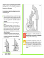
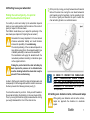
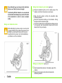
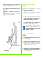
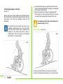
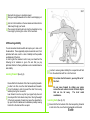
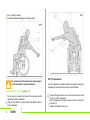
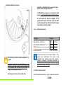
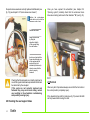
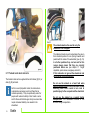
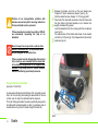
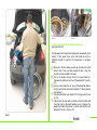
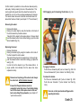
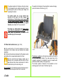
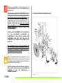
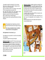
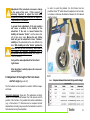
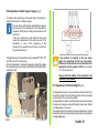
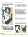
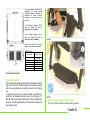
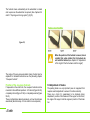
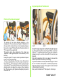
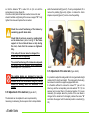
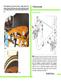
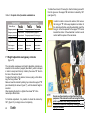
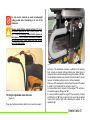
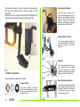
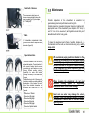
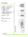
R
O
G
E
O
ActiveWheelchairs
User manual
Exelle
Rev. 3 - 15.10.04/IT
®
Contents
1.0 General Information
1.1 Introduction
1.2 Guide to symbols
1.3 General characteristics of the wheelchair
1.4 Use
1.5 General Advice
2.0 Safety
2.1 Movements: Getting in and out of the wheelchair
2.2 Learning how to use your wheelchair
2.3 Dealing with obstacles: stairs and steps
2.4 Dealing with ramps and slopes
2.5 Stability
2.6 Tyre pressures
2.7 Quick-release pins
2.8 Seat support tube placement
2.9 Foot rests
2.10 Calf straps
2.11 Tubular and desk arm rests
2.12 Fasteners
2.13 Wheelchair lifetime
2.14 Avoiding accidents
3.0 Transporting the wheelchair
4
4
4
4
5
5
5
5
7
7
10
11
12
13
14
14
15
16
17
17
17
17
20
4.0 General description of the wheelchair parts
5.0 Using the Wheelchair
5.1 Use
5.2 Opening system
5.3 Closing system
5.4 Lifting the wheelchair
5.5 Quick-release rear wheels
22
22
22
23
24
24
5.6 Using the brakes
5.7 Safety belts and harness
25
26
6.0 Adjustments
6.1 General
6.2 List of parts in standard set up
6.3 Adjustment of the back height
6.4 Adjustment of the rear wheel
6.5 Adjustment of front wheel height and fork angle
6.6 Adjustment of the back support angle
6.7 Adjustment of the footrest height
6.8 Adjustment of the footrest
6.9 Adjusting the brakes
6.10 Adjusting the back support
6.11 Adjusting the side rails
27
27
28
29
30
31
33
33
34
36
36
38
38
7.0 Accessories
7.1 Height adjustable swingaway armrests
7.2 Height adjustable desk armrests
7.3 Transit wheels
7.4 Anti-tip wheels
7.5 Tipping aid
7.6 Crutch holder
7.7 Other accessories
39
40
41
42
42
43
43
44
8.0 Maintenance
8.1 Replacement of worn parts
8.2 Inspection of components
8.3 Troubleshooting guide
45
46
47
47
48
9.0 Technical guide
49
10.0 Warranty
50
11.0 Certification
Exelle
3
General information to improve usage of the wheelchair by the
user.
1.1
Introduction
At RehaTEAM® constant research into quality and creativity are
the cornerstone of our business. After many years in the industry
we remain genuinely focused on providing total customer
satisfaction while bringing innovative style and design to every one
of our high-quality wheelchairs.
We have become industry leaders by making excellence and
service our top priorities. All of our models are built from carefully
selected materials and provide multiple configurations allowing full
personalization. We perform continuous, meticulous quality
control and testing in order to offer the highest possible quality
combined with fast, reliable service.
We acknowledge that we owe our success to our clients as well as
to those who have believed in us and helped us over the years,
providing us with the scope and inspiration to take the road less
travelled. We salute all those who, like us, believe that quality is the
best differentiator.
1.2 Guide to symbols
In this manual you will often see the following symbols which
are used to highlight points which are of particular interest or
importance:
This symbol indicates actions that must be avoided at all times
This symbol indicates that particular care should be paid to a
procedure or note in order to avoid causing harm to people or
things, or breakages and dangerous situations in general
4
Exelle
Essential tools: a flat screwdriver is necessary to perform this
procedure
Essential tools: a pozidrive screwdriver is necessary to perform
this procedure
Essential tools: a spanner is necessary to perform this procedure
Essential tools: a 6mm allen key is necessary to perform this
procedure
1.3 General characteristics of the wheelchair
The Progeo® EXELLE featherlite wheelchair has a particularly
evolved design. Ease of use and total personalization are just
some of the important features of this model.
The EXELLE is a high precision folding wheelchair with cross
bar system which ensures a very high level of rigidity and
manoeuvrability.
The EXELLE model offers a comprehensive range of innovative
solutions created in order to provide the greatest possible levels
of personalization in a featherlite frame .
The range of accessories available for this model make the
wheelchair extremely versatile and ideal for both indoor and
outdoor use.
1.4 Use
The EXELLE wheelchair is self-propelled which
means that it can be moved manually by using the
handrims on the rear wheels.
It can be used in rehab as well as more active
situations and is ideal for a wide range of users with
different kinds of pathologies.
It is used to guarantee either fully independant or
assisted (with an attendant) movement for a person
with reduced or fully impaired movement in one or more
parts of the body.
As it has such a large range of accessories and
configurations the wheelchair can be used in full
safety both inside and out.
Where the user has particularly severe pathologies or
with people who are unable to move at all on their own,
the assistance of an attendant is always advisable.
We also discourage use over hilly, particularly soft,
sandy or uneven ground, slopes exceeding the
recommended gradient and acid environments.
Its compact size and structure makes the EXELLE
wheelchair ideal for use by both teenagers and
adults.
General Advice
Before using the wheelchair we recommend that you
carefully read Chapter 2.0 Safety and Chapter 5.0
Using the wheelchair, which are essential to the safe
usage of the chair.
2.0 Safety
The
Progeo®
EXELLE
wheelchair
is
a
made-to-measure medical device and therefore it
should not be lent to other users even for short
periods of time.
Making any unauthorised modifications or using
un-approved parts may change the wheelchair
structure and create unsafe condition as well as
possible harm to the chair and occupant
THE MANUFACTURER WILL ACCEPT NO
RESPONSIBILITY
IN
CASES
OF
NONCOMPLIANCE WITH THE INSTRUCTIONS OR
RECOMMENDATIONS AS SET OUT IN THIS
MANUAL AND ANY SUCH ACTIVITY WILL RESULT
IN THE IMMEDIATE CANCELLATION OF THE
MANUFACTURER S WARRANTY
2.1 Movements:
Getting in and out of the wheelchair
While getting in or out of the wheelchair do not place
your feet on the front foot rest. This could result in
the wheelchair tipping over possibly causing harm both
to the chair and the occupant.
Getting in and out of the wheelchair must always be done with
extreme care and caution, even by experienced occupants, and
must be performed only after receiving instruction from
specialised and fully trained personnel.
Exelle
5
If getting into and out of the wheelchair is difficult an attendant
should be present. All of these actions should in any case be
performed based on your particular pathology and therefore on
your own level of independence.
The general rules to respect while getting into or out of the
wheelchair safely are:
Ensure the wheelchair is parked on a solid, flat or regular
surface. Do not get into or out of the wheelchair while on hills or
broken ground which could render the wheelchair unstable and
cause the occupant to fall and/or the wheelchair to
overbalance.
The brakes should be on (see chapter 5.6 Using the
brakes )
Move your feet off the foot rests (or raise the foot rest, see
chapter 2.9 Foot rest ) in order to get out of the wheelchair.
Move them close to the foot rest before getting into the chair.
Lean on the wheelchair and where possible on a stable
object nearby. Lean onto the armrests to raise and move
your body (see fig. 1).
In cases where the occupant is not able to perform this
movement alone, or if the movement is to be performed on
an unstable or difficult surface, an attendant should be
present (see fig. 2).
While getting into or out of the wheelchair never
lean or sit on the clothes protector. It could bend
or break possibly resulting in injury.
If your wheelchair is equipped with armrests, these
should be removed (for desk armrests) or turned out
(for movable armrests) on the side that you will get in or
out of. (see chapter 7.1 Fully adjustable swing-out arm
rest and chapter 7.2 Fully adjustable desk swing-out
arm rest
2.2 Starting to use your wheelchair
Finding the centre of gravity the point at
which the wheelchair will tip back
Your ability to control and safely tip the wheelchair depends
mainly on your seating position and the location of the centre of
gravity in respect to the rear wheels.
The EXELLE model allows you to adjust the positioning of the
rear wheels (see chapter 6.4 Adjusting the rear wheels )
At this point by moving your body backwards and forwards
while at the same time moving the rear wheel backwards
and forwards using the handrails, it will be possible to find
the centre of gravity and therefore the point at which the
chair will safely tip back in a controlled manner.
Remember that every adjustment to the rear wheels
influences wheelchair stability and could therefore
increase the possibility of it overbalancing.
The correct positioning of the rear wheels depends on
many factors, among them: the occupant s weight, type
of disability and ability to manoeuvre the wheelchair.
The manufacturer will supply the wheelchair with the
rear wheels positioned according to instructions given
on the original order form.
Finding the point at which the chair will safely tip
back requires the presence of an attendant who
must be standing behind the wheelchair ready to
prevent it from overbalancing.
In order to find the point at which the chair will tip back easily and
consequently to find the range within which it is safe to manoeuvre
the chair, proceed in the following manner (see fig. 3):
You should be seated in your chair. Slide yourself forwards in
the seat while holding the handrims on the rear wheels tightly.
Then, by moving the handrims slightly backwards while moving
your weight backwards the front of the chair will rise.
IN ORDER TO PREVENT THE WHEELCHAIR
FROM
OVERBALANCING DURING NORMAL
DAILY USE, WE RECOMMEND MOUNTING THE
ANTI-TIP WHEELS WHICH ARE SUPPLIED AS AN
ACCESSORY TO THIS MODEL. (see chapter 7.4
Anti-tip wheels )
2.3 Getting over obstacles: kerbs, inclines and ramps
While getting over obstacles such as kerbs, inclines,
ramps etc, approach the obstacle at a moderate
speed.
Exelle
7
Never attempt to go over steps or other obstacles
that are over 20cm (6 inches) in height.
If particularly difficult obstacles are encountered
an attendant should always be present at the back
of the wheelchair in order to ensure complete
safety.
Going over obstacles alone
Before attempting to go down a step or over any kind
of general obstacle alone (without the presence of an
attendant), you will need to have control over your
wheelchair and know how to tip it while maintaining
your balance over the rear wheels.
Going down steps on your own (see fig. 4)
Bring the wheelchair right up to the leading edge of the
obstacle so that the front wheels are touching it.
Raise the front wheels by tilting the wheelchair while
maintaining balance.
Move the rear wheels carefully up to the obstacle. During
this phase hold the handrims tightly.
Once the rear wheels have descended the obstacle and are
on the ground, lean the wheelchair forward until the front
wheels touch the ground again.
f igur a 5
Going up a step alone (see fig. 5)
Take the wheelchair right up to the leading edge of the
obstacle.
Raise the front wheels and tip the chair back while
maintaining balance.
8
Exelle
Using the handrims, carefully move the rear wheels forwards
until the wheels are touching the edge of the step.
Tip the wheelchair forwards until the front wheels are on top of
the obstacle.
Lean forward in the chair so that the rear of the chair is
lighter.
Hold the handrims tightly and move the rear wheels forwards
bringing them over the top of the obstacle.
Going down steps with an attendant
(see fig. 6)
Take the wheelchair right up to the obstacle so that the front
wheels are as close as possible to it.
Grip the rear handles tightly and push down in order to raise
the front of the wheelchair.
Keep the wheelchair in this position and accompany it down
the stairs one step at a time. The occupant seated in the
chair can assist the attendant by using the handrims.
At the end of the descent, tip the chair forward so that the
front wheels are once again touching the ground.
In order to facilitate the raising of the chair by an
attendant we advise the use of the tip-back assistance
device which is supplied as an accessory to this model
(see chapter 7.5 Tipping aid )
Going up steps with an attendant
(See fig. 6)
Move backwards towards the step so that the rear wheels of
the chair are touching it.
Grip the rear handles of the chair tightly and pull hard while
keeping the wheelchair tilted (with the front wheels raised in
order to prevent the occupant from slipping out of the chair),
and pull the back wheels up over the step.
Keeping the chair in the tilted back position, move away from
the steps before tipping the chair forwards until the front
wheels are touching the ground.
2.4 Going up slopes or inclines
(See fig. 7)
Moving up any kind of slope should be done with extreme care.
The occupant must move at speed by generating force on the rear
wheel while at the same time maintaining control over the
wheelchair.
We recommend that occupants who have not yet
completely mastered safe use of the chair should
mount the anti-tip system which is supplied as an
accessory to this model and which is useful in
preventing the chair from tipping over backwards
(see chapter 7.4 anti-tip wheels ).
Lean forwards and keep your weight forward in the chair in
order to prevent the wheelchair from tipping over backwards.
Hold the rear handrims tightly.
Move the wheelchair up the slope energetically whilst
ensuring that you move smoothly and fluidly. Do not move
your upper body backwards and forwards in the chair.
The maximum gradient that can be attempted in
complete safety is 6% (3°)
Going downhill (see fig. 8)
In order to go downhill safely, the occupant must maintain
constant, controlled speed and direction over the entire slope.
10
Exelle
Approach the slope at a moderate speed
Keep your weight backwards in the chair to avoid slipping out
Hold on to the handrims on the rear wheels and allow them to
slide slowly through your hands.
The occupant should be able to stop the wheelchair at any
time simply by blocking the motion of the handrails.
2.5 Ensuring stability
You will encounter situations which will require you to lean out of
the wheelchair. These apparently simple movements could, if not
performed with care, result in a loss of stability and the possible
overbalancing of the chair.
In order to gain the maximum control over your wheelchair the
following list of situations is given. We ask that you pay
particular attention to these guidelines so as to maintain balance
and stability.
Leaning forward (See fig. 9)
Ensure that the front wheels of the chair are pointing forwards.
In order to do this, move the chair backwards and forwards.
Put on the brakes in order to prevent the chair from moving
suddenly during the movement.
Lean forward in such a way that your upper body does not
move beyond the front wheels at any time. Moving the weight
of the body excessively forward may cause the wheelchair to
tip up onto the front wheels and overbalance possibly causing
harm both to the chair and the occupant.
In order to ensure greater stability the occupant should hold
on to the wheelchair with his or her free hand.
Do not lean too far forward
the chair.
you may fall out of
Do not move forward by sliding your pelvis
across the seat cushion in order to reach objects
that are too far away.
The chair could
overbalance.
Leaning back (See fig. 10)
Ensure that the front wheels of the chair are pointing forwards.
In order to do this, move the chair backwards and forwards
Exelle
1
Do not use the brakes
Lean back without changing your seating position
Do not lean too far back over the back support
as the wheelchair could overbalance.
2.6 Tyre pressures
In order to guarantee consistent, precise running and braking it is
necessary to ensure that the tyres are correctly inflated.
Leaning out to the side (see fig. 11)
Do not move your upper body beyond the rear wheel as the
wheelchair could overbalance.
With your free hand, for greater safety and stability, hold on
to the wheelchair.
12
Exelle
Remove the plastic valve cover on the valve which is found
on the rim of the rear wheel.
Use a compressor to bring the pressure to the correct level
(see table 1).
Replace the plastic valve cover
Replace the plastic valve cover
wheelchair noticeably easier to move and gives
greater control during manoeuvres.
To inflate the tyres always use a compressor with a
gauge. Do not use hand pumps or other systems.
Do not exceed the pressure indicated in the
pressure table as the inner tube or the tyre itself
may be damaged. Pay particular attention to type
of tyre fitted, as shown in table 1.
Table 1 : Rear tyre pressures
Tyre type
Pressure
High pressure, smooth tyre
High pressure, treaded tyre
Tubeless tyre
7 bar
7 bar
10 bar
Puncture-proof tyre
Check the tyre pressures weekly using table 1 as
a guide.
700 kPa
700 kPa
1000 kPa
does not require inflation
Puncture-proof tyres do not require inflation. They
require less maintenance and reduce costs
associated with replacing tyres after puncture.
However, compared to standard pneumatic or
tubeless tyres the puncture-proof tyres will feel slightly
less smooth during normal use.
Incorrect inflation of the tyres (above all if the
pressure is too low) causes incorrect functioning
of the brakes and the chair may not stop (see
chapter 6.9 Adjusting the brakes ).
2.7 Quick release axels
Ensuring correct tyre pressure makes the
After each procedure carried out on the rear wheels, ensure that
Exelle
1
the quick-release axels are correctly replaced and fastened (see
fig. 13) (see chapter 5.5 Quick-release rear wheels )
Once you have opened the wheelchair (see chapter 5.2
Opening system ) carefully check that the under-seat cross
tubes are correctly positioned in their brackets A (see fig. 14).
Perform the quick-release
axels check up only while the
wheelchair is not in use.
Release the brakes
Raise the rear wheel
by lifting the
wheelchair slightly
off the ground using
the rear handles.
Take hold of the wheel
bush in one hand with the
fingers laced through one
or two spokes and pull
and push firmly (as
indicated by the arrow) in
order to ensure that the
wheel is properly
fastened.
Checking that the rear axels are correctly positioned is
one of the regular maintenance procedures that should
be carried out by the occupant.
If the axels are not correctly replaced and
fastened they may work loose during normal
use resulting in the wheelchair overbalancing
and possibly causing injury.
2.8 Checking the seat support tubes
14
Exelle
2.9 Footrest
After every kind of procedure always ensure that the foot rest is in
the correct position (completely open).
If the wheelchair has split foot rests (see fig. 15) ensure that both
are fully lowered before using the chair.
2.10 Calf restraints
With the single flip-up foot rest (fig. 16) ensure that the locking pin
A is correctly inserted into it s fixing mount B .
In some cases, depending on the diameter of the front wheel and
the overall length of the wheelchair, the front wheel, as it rotates
for turns etc may come into contact with the occupant s heel.
In order to avoid any such contact (which could result in the chair
overbalancing), the chair is supplied with a calf restraining belt
which should be adjusted so that the occupant s feet do not
come into contact with the wheels of the chair at any time
(see fig. 18).
Exelle
1
Fig 20
The armrests must not be used to carry the
wheelchair or as a support.
2.11 Tubular and desk armrests
The Exelle model can be supplied either with tubular (fig 19) or
desk (fig 20) armrests.
As this is a self-propelled model, the armrests are
considered an accessory and must therefore be
ordered separately. They are particularly useful for
people with reduced mobility in their hands or arms
and for those with limited upper body movement who
require increased stability once seated in the
wheelchair.
16
Exelle
The tubular armrests are only locked when they are in
their standard position for use (facing forwards and
parallel with the sides of the wheelchair) (see fig. 19).
In all other positions they can turn and for this
reason always ensure that they are correctly
positioned before use (see chapter 7.1 Height
adjustable, quick-release, swingaway armrests ).
If this instruction is ignored the wheelchair and
the occupant could overbalance.
Do not use the armrest as a hand hold when
moving the wheelchair as this could result in them
becoming loose which could in turn lead to
possible injury to the occupant and the wheelchair
Do not use the armrest as a support during
transportation. We recommend removal of the
armrests during transportation.
2.12 Tightening hardware - nuts, bolts, screws etc
After each maintenance cycle ensure that all nuts,
bolts and screws are correctly tightened as they may
loosen during normal daily use.
We recommend checking that all hardware is
correctly tightened at least once a month. If
necessary consult an authorized PROGEO dealer
or mechanic.
Speed
Always adjust your speed based on the type of terrain and
conditions. Generally we advise a constant, regular speed,
avoiding sudden acceleration or changes in direction.
Using the brakes
2.13 Wheelchair lifetime
Under normal daily use the PROGEO wheelchair has a lifetime
of 5 years provided that it receives careful maintenance at the
correct intervals.
The lifetime will be considerably increased if the wheelchair is
only used indoors or not on a daily basis.
The parking brakes have been designed to hold the
wheelchair stable when it is stationary.
For safety reasons we do not recommend using
the parking brakes while the wheelchair is in
motion (see chapter 6.9 Adjusting the brakes ).
When using the brakes care should be taken to
avoid injury to the hands or fingers.
2.14 Avoiding accidents
Movements
Avoid sudden, jerky movements during use of the wheelchair
to avoid overbalancing
If obstacles are encountered, avoid sudden movements
(such as abrupt braking).
The possibility of skidding increases when the terrain is
damp or uneven.
Approach obstacles such as steps or entry ways with care (get
help from an attendant).
For greater security it is recommended that any movements
on slopes or other dangerous terrain should be performed in
the presence of an attendant.
3.0 Transportation of the wheelchair
There is no single best way to transport the wheelchair in a
vehicle. The kind and level of disability the patient has, his or her
ability to control upper body, arm and hand movements, strength
and the kind of vehicle that will be used are all factors. For an
elderly or very young occupant, moving the wheelchair without
assistance will be difficult.
Taking all of these variables into consideration, we cannot provide
valid instructions for every possible scenario so here we supply
some general information.
Exelle
1
Perform all car transportation activities with
extreme care and only after receiving instruction
from specialised service personnel.
If these procedures seem to be unsafe or difficult
we recommend requesting the help of an
attendant.
Never transport an occupant in a vehicle while
seated in the wheelchair as these wheelchairs
are not designed for this kind of use.
If the occupant must be transported while seated
in the chair you are reminded that the wheelchair
in its standard configuration is not supplied with
seatbelts. Any safety belts for vehicle transport
must be installed by specialised personnel.
Transport with an attendant
(see figs. 21-22-23-24)
In cases where the physical limitations of the occupant prevent
him or her from moving and loading the wheelchair into the car
on their own, the help of an attendant will be required.
This fully folding wheelchair has been specifically designed to
be lightweight and manageable in order to guarantee ease of
movement even by those of limited strength and mobility.
18
Exelle
Release the brakes and pull out the rear wheels (see
Chapter 5.5 Quick release rear wheels ) (see fig. 21).
Fold the wheelchair (see chapter 5.3 Closing system ).
Take hold of the chair with one hand on the front frame and
the other hand on the back handles so as to balance the
weight and make lifting easier.
Load the wheelchair into the car along with the rear wheels
(see fig. 22).
The reduced size of the folded chair allows it to be loaded
into the boot of the car (fig. 23) or between the front and rear
seats (see fig. 24).
figura 23
figura 24
Loading the wheelchair without assistance
(see figs 25-26-27)
The following actions have been designed for people with good
control of their upper body, arms and hands as well as
sufficient strength to perform the movements in complete
safety.
Move up to the door where you will get into the car (E.g the
driver s door). Once you have opened the door move the
chair as close as possible to the seat.
Put on the brakes and get into the car (see chapter 2.1
Movements: getting into and out of the wheelchair ) (see fig.
25).
Once you are inside the car, put on the wheelchair brakes
and pull out the rear wheels (see chapter 5.5 Quick release
rear wheels ).
Fold the wheelchair (see chapter 5.3 Closing system ) (see
fig. 26).
Take hold of the chair with one hand on the front frame and
the other hand on the back handles so as to balance the
weight and make lifting easier. Load the chair and the rear
wheels into the car. (See fig. 27)
Exelle
1
General Description of the wheelchair parts
General description of the Wheelchair parts ( see fig. 28)
- Titanium
- Rubber Ultra grepp
- PU Max grepp
- Rubber and aluminium Ergo-Para
- Aluminium with rubber inserts Dual grepp - rudder
- Silicone anti-slip ring for use on the wheel hub
1 Padded, breathable back support, fully adjustable via the
Velcro straps.
2
3
Titanium back support tube adjustable in 1.5 cm increments:
- Short tube adjustable from 30 to 42 cm
- Long tube adjustable from 42 to 54 cm
Clothing protector:
- ABS, Straight
- ABS, curved
- Carbon fibre, curved
- Pull-out, curved
4
5
Aluminium pins for locking and adjusting the clothing protectors
Seat base with Velcro straps for securing the seat cushion,
supplied with a handy pocket for personal belongings.
6
Front of the frame.
7
Fully adjustable Velcro calf support /restraint.
Front footrest support tubes, long and short, with height
adjustment holes every 1.5 cm, with an external protecting sleeve.
1
1
1
2
1
3
1
4
1
5
Quick release axel.
1
6
1
7
1
8
Front forks.
8
9
10
Rear wheels:
- Smooth high pressure pneumatic tyres
- Gripped high pressure pneumatic tyres
- Tubeless tyre
- Puncture-proof tyre
Hand rail:
- anodized aluminium
Rear wheel adjusting plate.
Rear frame.
Cross system tubing.
Front wheel:
- 3 sport - hard solid rubber
- 4 PU soft, solid rubber
- 4 active with aluminium alloy wheels
- 5 softroll - soft, solid rubber
- 6 pneumatic
- 7 PU with soft, solid rubber
Fork supports.
Brakes:
- Curved lever
- Straight lever
- Extended removable lever
- Under-seat sport brake
- Disc brake for use by attendant
Exelle
21
19 Foot rests:
- Single, fibre, height adjustable
- Split, fibre
5.0 Using the wheelchair
In order to prevent overbalancing, the maximum
gradient recommended for this wheelchair is 3°
(6%). (See chapter 2.4 Dealing with ramps and
slopes ).
The maximum weight that the Exelle model is able
to carry safely is 125kg.
5.1 Use
The featherlite Exelle wheelchair is a high-precision cross
system folding wheelchair.
Because of it s characteristics of reduced weight, adaptability
(configuration) and smoothness this wheelchair is ideal for daily
use both by occupants with severe pathologies (with limited
movement in the legs, arms and upper body) as well as more
active occupants (able to perform activities without assistance).
The wheelchair has been designed for indoor (flats, gyms,
schools, libraries, etc...) as well as outdoor (roadways,
pavements, courtyards, etc...) use.
During day-to-day use of the wheelchair the occupant
could encounter broken or irregular ground (such as
gravel, holes etc) or slippery terrain (wet ground,
sandy, dusty or oily round etc). In these cases and all
other cases where the use of the chair could be
difficult or even dangerous (both for the occupant
and for the wheelchair itself), we recommend using
maximum care and attention combined with
smooth motion avoiding sudden braking or
acceleration (see chapter 2.0 Safety ).
22
In cases of extreme difficulty or danger it is
always advisable to have the assistance of an
attendant.
Exelle
Opening the wheelchair (fig 29)
Always use great care that your fingers are not
caught in the cross-system of the chair during
folding and unfolding. (fig. 31).
Remove the seat cushion or other soft support from the
seat.
Place the palms of your hands on the 2 seat tubes in
positions A & B (fig. 29), and push down hard.
In order to make this operation easier it is a good idea to
raise one of the rear wheels slightly. In order to do this hold
onto one of the rear handles of the chair and raise it.
With your other hand push down hard on the seat support
tubes (fig. 30).
Ensure that the tubes on the seat are correctly positioned in
their brackets (see chapter 2.8 Seat support tubes ).
Lower the footrest (This will not be necessary if a flip-up
footrest is fitted).
5.3 Closing the wheelchair (fig 32)
Remove the seat cushion or other soft supports from the seat
and /or seat back
Raise the footrest/s (This will not be necessary if a flip-up
footrest is fitted).
Pull the seat upwards using both hands in positions A & B
(fig. 32).
5.4 Lifting the Wheelchair (fig. 33)
The wheelchair can be lifted and transported in many
different ways. However it is advisable to fold the
wheelchair down to facilitate these actions.
In order to reduce weight, remove the rear wheels (see
chapter 5.5 Quick release rear wheels ) and close the
wheelchair. In order to have greater balance while
lifting (see chapter 5.3 Closing system ) take hold of
the wheelchair using one of the rear handles and the
front frame of the wheelchair (see fig. 33).
Quick-release rear wheels (figs 34 & 35)
24
Exelle
On this model it is possible to remove the rear wheels quickly
and easily, thereby reducing the size of the wheelchair. This
can be particularly useful when the wheelchair needs to be
loaded into a car or put into a narrow passageway for storage.
The transit wheels are used to facilitate movement when the
wheelchair has been folded. (see chapter 7.3 Transit wheels ).
5.6 Engaging and releasing the brakes (fig. 36)
Removing the wheel
Release the brakes
Raising the wheel slightly using the handles on the back of
the chair makes this procedure easier.
Take hold of the wheel by the spokes close to the axel bush,
push the release button in and, without letting go, pull the entire
wheel outwards (fig. 34).
Replacing the wheel
Release the brakes
Raising the wheel slightly using the handles on the back of
the chair makes this action easier.
Take hold of the wheel by the spokes close to the axel bush,
push the release button in and, without letting go, replace the
axel (fig. 35).
In order to lock the wheel let go of the release button. A
single audible click indicates that the wheel has been
replaced correctly.
Removal and replacing of the wheel must always
be carried out with the brakes released.
Ensure that the quick-release axels are
completely locked into place. Check this by taking
hold of the wheel at the spokes close to the axel
bush and pulling firmly outwards. (see chapter 2.7
quick release axels ).
figura 36
To engage the brakes
Push the lever forwards (with push-on brakes fig. 36/b. Pull
the level backwards if pull-on brakes are fitted fig. 36/a).
To release the brakes
Pull the lever backwards (with push-on brakes fig. 36/b.
Push the lever forwards if pull-on brakes are fitted fig.
36/a).
Take care not to injure hands and fingers while
operating the brakes
Exelle 25
The optimum position for the brake on the tyre is about
0.5 cm between the tyre and the brake bar (0.6 cm if
puncture-proof tyres are fitted) (see chapter 6.9
adjusting the brakes ).
The waist belt is fastened to the wheelchair via two anchorage
points at the back of the frame (fig. 37).
The brake works via a lever which acts
directly on the tyre. For this reason the
effectiveness of the braking system depends on
the tyre being correctly inflated. We highly
recommend checking tyre pressures at regular
intervals. (see chapter 2.6 Tyre pressures ).
The brake is a safety feature and must not be
used while the wheelchair is moving as this
could cause the wheelchair to overturn with
possible injury to the occupant.
5.7 Waist belt and harness (figs. 37-38)
Both the waist belt (fig. 37) and the harness (fig. 38) are
accessories to this model and must therefore be ordered
separately.
Both of these belt systems are designed to offer greater security
and stability to the occupant while seated in the chair.
Both the waist belt and harness system are of
particular use to occupants with little control of their
upper body and who require extra support in order to
be held securely in the seat during use.
The waist belt (fig. 37) holds the occupant in the chair around
the waist and leaves the upper body free for movement.
26
Exelle
The harness system (fig. 38) holds the occupant in the seat at
his or her waist and shoulder. The entire upper body of the
occupant is secured. It is intended for use by occupants with
particularly limited mobility in the upper body.
The harness system is fastened to the wheelchair via four
anchorage points on the rear of the frame (fig. 38).
6.0 Adjustments
Use of belt and harness
Using the waist belt (figs 37-39) and harness system (figs
38-40) is fairly simple.
Before sitting in the wheelchair the occupant should open the
buckles by pressing on both sides of each buckle while pulling
the two parts open (fig. 41).
Once seated in the chair with the belt or harness in place the
occupant can close the buckles (figs 39-40) by fitting the two
parts together (fig. 42).
General
The
PROGEO
Exelle
wheelchair
is
a
made-to-measure medical product based on the
specifications detailed on the original order form
for the patient by qualified personnel. We strongly
advise users against lending the wheelchair to
other users even for brief periods.
The wheelchair measurements have been set after
a careful study of the requirements of the user who
originally purchased it and the features of
maneuverability, stability and durability are
guaranteed only for that user.
Exelle Vario 27
Lending your wheelchair to others could cause it to
function unsafely and tip over with potentially serious
consequences.
The wheelchair supplied by RehaTEAM® has been
tested and set up to ensure optimum performance.
It is forbidden to carry out any modifications (even
when possible) different to the original design. All
modifications which can be made by the user are
detailed in this chapter but must only be carried
out as maintenance , in order to return it to its
original condition (the condition in which it was
originally supplied).
6.2 List of parts for standard set up
Always contact RehaTEAM® and its technicians
for
any
non-standard
requirements
or
modifications to allow them to evaluate such
modifications and verify that they will not
compromise the normal use and safety of the
wheelchair.
Any modification of the original parameters and
set up could seriously compromise the safe
operation of the wheelchair causing harm both to
the user and the wheelchair itself.
After each adjustment made to the wheelchair, check
carefully that all parts are correctly fixed. Check that
all screws and nuts are tightened and that all moving
parts are functioning correctly.
Have the adjustment of your wheelchair checked at
least every 3 months by personnel qualified and
authorized to carry out maintenance on
PROGEO® products.
figura 43
28
Exelle
Description of parts for standard set up (fig 43)
Pos. Description
1
2
3-4
5
6
7
8
9
10
11
12
13
14
15
16
17
18
19
20
21
22
23
24
25
26
27
28
29
30
31
32
33
Rear frame left and right
Washer
Frame connecting tube
Screws TCEI DIN 912 steel 6x25
Self-locking nut. Bottom DIN 985 steel M6
Screw TCEI DIN 912 steel 6x30
Flat washer DIN 125 steel 6x12x1.5
Self-locking nut. Top DIN 982 steel M6
Washer in black plastic 16x25x1
Cross bar
Front frame left and right
Seat fabric
Fabric fixing rail
Screw TSPEI DIN 7991 steel 5x35
Screw TSPEI DIN 7991 steel 5x18
Screw washer conical aluminium 5x16x3
Self-locking nut. Bottom DIN 985 steel M5
Cross tube sideguard support
Aluminium side guard
Screw TSPEI DIN 7991 steel 5x50
Flat washer DIN 125 steel 5x10x1
Self-locking nut. Top DIN 982 steel M5
Titanium back support tube
Screw TCEI bottom DIN 7984 8.8 6x30 Z.B.
Top back support strap
Back support tube
Back support padding
Round tube plug dim.20
Grip in rubber
Screw TSC+Autofil.DIN 7983 steel 4.8x16
Rear wheel fixing plate left and right
Front wheel and fork unit left and right
Quantity
1l+1r
8
2+2
4
6
4
10
4
16
1
1l+1r
1
2
6
2
14
12
4
2
4
10
6
2
2
1
1
1
2
2
4
1l+1r
1l+1r
34
35
36
37
38
39
40
Parking brake left and right
Rear wheel unit complete
Side guards left and right
Screw TSPEI DIN 7991 steel 5x14
One-piece footrest
Screw TCEI bottom DIN 7984 8.8 5x30 Z.B.
Calf support strap
6.3 Adjustment of the back height (fig 44)
1l+1r
2
1l+1r
4
1
2
1
It is possible to adjust the back height in 1.5cm intervals.
Remove the rear wheel (see chapter 5.5 Removal of rear
wheels ) to carry out the adjustment.
Using a 4mm Allen key and a 10 mm spanner, remove screws
A and corresponding nuts and washers A1 .
Next, using a 5mm Allen key and a 10mm spanner, remove
screw B and corresponding nut and washer B1 .
Repeat the procedure for both sides of the wheelchair.
Raise or lower the back to the desired height.
Replace the screws into the nearest pre-drilled holes in the frame
and tighten.
When adjusting the back height make sure that the
height on the left is the same as the height on the right.
After carrying out adjustment make sure that the
screws and nuts are securely tightened.
6.4 Adjustment of rear wheel (fig 45)
This adjustment is very important to ensure the correct stability
of the wheelchair.
It is possible to adjust both the height and depth.
Adjustment of height: the plate K of the rear wheel support
can be positioned at six different heights. Proceed by removing
the rear wheel (see chapter 5.5 Removal of rear wheels ).
Remove fixing screws A (4 mm Allen key) and corresponding
nuts and washers A1 (10mm spanner). Move the mounting
plate up or down in line with the corresponding holes on the
frame, pre-drilled at 1.5cm intervals.
Replace the screws and tighten.
30
Exelle
Adjustment of depth: six different positions are possible for the
wheel alignment axle B . The plate K permits axle B to be
positioned in three positions corresponding to the three holes F .
By rotating the plate 180° (see fig 45) it is possible to obtain a
further three positions. Remove the rear wheel (see chapter 5.5
Quick release rear wheels ).
To adjust the depth, remove the axle B (24 mm spanner) and
the corresponding nut and washer.
If it is necessary to rotate the plate, remove screws A (4 mm
Allen key) and corresponding nuts and washers (10 mm
spanner).
Once the components are in the required position replace the
screws and tighten all parts.
Adjustment of the rear wheels can cause a change
to the angle of the seat. If this occurs it is
extremely important to adjust the front wheel
support by following the instructions in chapter 6.5
Adjustment of front wheels .
In order to avoid this problem, the front frame has four
pre-drilled holes F which allows the adjustment to be made,
to increase or decrease the distance between the front wheels
and the footrest.
In general terms adjustment of the axle position
will cause a variation to the stability of the
wheelchair. If the axle is moved forward the
stability will become Active and the wheel chair
will tip back more easily. Moving the axle further
back will give the wheelchair a more Cautious
stability and the wheelchair will be more difficult to tip
back. With stability set in the Active position the
wheelchair will tip over more easily. When used in
this setting we therefore recommend that an
appropriate anti-tip system is fitted (see chapter 7.4
Anti-tip wheels )
Carry out the same adjustment for the left and
right wheels.
After adjustment, carefully replace all screws and
nuts and tighten.
6.5 Adjustment of the height of the front wheels
and fork angle (figure 46-47)
Table 2 : Comparisonbetweenfrontwheels, forktype andfrontheight
The front wheels can be adjusted in a number of different ways
as follows:
Horizontal adjustment (figure 46): This adjustment is strictly
related to the relationship between the front wheels and the
position of the footrests. It is possible that certain combinations
(e.g. a front wheel of 7 dimension and a one-piece footrest
adjusted fully internally) may cause the front wheels to touch the
footrest when turning the wheelchair.
Exelle
31
To adjust the position remove the two screws A and B
(using a 5 mm Allen key). Position the fork support correctly
ensuring that during the rotation of the forks around their
vertical axis there is no contact between the front wheels and
the footrests. Once in the desired position, replace the screws
correctly, aligning them with the pre-drilled holes in the frame.
Tighten firmly.
Adjustment of the angle (figure 46): It is necessary to ensure
that the axis of the forks is at 90° to the ground.
This operation is carried out by removing the fixing screw A
(using a 5 mm Allen key) and changing the position of the
eccentric hexagon A1 which is situated on the inside edge of
the fork support. Once the correct position has been located
re-insert the hexagon in the support and tighten firmly.
Adjustment of the angle of the front wheels
needs to be checked periodically in order to
ensure that the axis of the fork always remains at
90° to the ground.
Adjustment or at least checking will in any case be
necessary any time the rear wheels are moved
(see chapter 6.4 Adjustment of rear wheels ).
Adjustment of the height of the front wheels (fig 47): This
adjustment is necessary in order to maintain the correct height
of the front of the wheelchair.
The height of the front of the wheelchair depends on the
dimensions of the front wheel and the type of fork used (e.g. with
a wheel of 5 and a medium fork it will be possible to obtain front
heights of 44/45/46/47 cm) (see table 2).
To adjust the height remove screws C (using a 4 mm Allen key)
and adjust the wheel in line with the pre-drilled holes on the forks
32
Exelle Vario
(hole n°2 for short forks, hole n°4 for medium forks, hole n°5 for
long forks).
Replace screws and tighten firmly.
Adjustment of the front height becomes
necessary after the front wheels have been
replaced with wheels of different dimensions or
simply because the user wishes to modify the
height of the front of the wheelchair.
Every time the height is adjusted it is also
necessary to check and adjust the angle.
6.6 Adjustment of back support angle (fig 48)
To obtain correct positioning of the upper body it is possible to
adjust the backrest to 5 different angles.
The rear frame with backrest adjustable for angle is
an accessory for this wheelchair. It must therefore be
requested at the time of ordering and selected on the
order form.
It may be mounted at a later date but this would
require the replacement of the entire rear unit of the
wheelchair. In view of the complexity of this
procedure, the operation should only be carried out
by qualified personnel.
To adjust the angle of the backrest, remove screws D , D1 , E
and E1 (use a 5 mm Allen key).
Ad just the backrest to the desired angle (see figure 49), replace
the screws through one of the pre-drilled holes in the backrest tube
and tighten firmly.
Fig. 49
If the backrest is adjusted to the rear (open
angle), the wheelchair will tip over more easily.
When used in this position we recommend that an
appropriate anti-tip system is fitted (see chapter
7.4 Anti-tip wheels ).
Always check the stability of the wheelchair in the
presence of an assistant.
6.7 Adjustment of footrest height (fig 50)
This adjustment serves to vary the distance of the footrest from
the seat to enable the correct sitting position of the user based
on the height of the user and leg length.
This adjustment is valid for both the double-piece and one-piece
footrests and one-piece automatic folding footrest (see chapter
6.8 Adjustment of footrests ).
The support tube for the footrest has five pre-drilled holes, and the
frame has a further two holes drilled, giving a total of ten positions
of height adjustment.
Exelle 33
Remove screws A and corresponding nuts and washers (use a 3
mm Allen key and an 8 mm spanner). Slide the footrest support
tube up or down to the desired position. Replace the screws in the
nearest available holes and tighten firmly.
6.8 Adjustment of the footrest
The Exelle model can be equipped with three different types of
footrest: double footrests (figure 52), one-piece footrest
(figure 53) and one-piece automatic folding footrest (figure
54).
Any one of the three types of footrest can be mounted based on the
specific requirements of the user.
When raised, the one-piece footrest and the double footrest
enable the user to place their feet on the ground. The one-piece
automatic closing footrest does not offer this facility.
The one-piece footrests are more rigid and durable than the
double footrests. For this reason they are recommended for
those users who experience strong contractions of the lower
limbs and who tend to apply frequent sustained pressure on the
footrests.
Double footrests
These can be raised very easily by pulling up with one hand on
the individual footrests themselves (figure 51).
The double footrests can be adjusted for angle to ensure the best
foot contact for the user.
To adjust the angle remove screw A (use a 5 mm Allen key),
rotate the footrest as indicated by the arrow up or down to the
required position (figure 52). Replace and tighten the screw firmly.
In order to avoid hitting objects which could cause
the wheelchair to tip over, we recommend
maintaining a minimum distance between the base
of the footrests and the ground of not less than
2cm.
After adjustment tighten all screws firmly.
34
Exelle Vario
To comply with Norm UNI EN 12183
paragraph 6.1, when double
footrests are fitted it is necessary to
maintain the correct distance
between the two footrests when
lowered:
1) The footrest distance (DIST)
must not exceed 35 mm for
wheelchairs used by adults.
2) The footrest distance (DIST)
must not exceed 25 mm for
wheelchairs used by children.
Below are detailed the correct
footrest sizes based on seat width:
EXELLE Model
Seat width
Footrest type
33
36
39
42
45
48
140 x 160
150 x 160
170 x 160
NO
200 x 160
NO
One-piece footrest
This model can be raised by pulling up the footbed with one hand
(figure 53). When the footrest is lowered, be careful to ensure
that the securing bracket is correctly inserted into the locating
lug.
To adjust the angle of the one-piece footrest it is sufficient to
loosen the four headless screws, (use a 3 mm Allen key) L
and M (two for each tube). Rotate the footrest, as indicated by
the arrow, until the desired position is reached and re-tighten the
four screws (fig 54).
One-piece automatic closing footrest
This type of footrest does not require closing by hand.
Exelle 35
The footrest closes automatically as the wheelchair is closed
and re-opens as the wheelchair is opened. (See chapters 5.2
and 5.3 Opening and closing system ) (fig 55)
(figure 55)
When the position of the footrest is moved, check
carefully that, when rotated, the front wheels do
not touch the footrest (see chapter 6.5 Adjustment
of the height of the front wheels and fork angle ).
The angle of the one-piece automatic closing footrest can be
adjusted. For detailed instructions see the preceding chapter
One-piece footrest .
Position of the one-piece footrests
If requested on the order form, the one-piece footrests can be
mounted in three different positions: 2/3 internal (figure 56-59),
completely internal (figure 57-60) or completely external (figure
58-61).
These configurations depend exclusively on how the parts are
assembled (two Allen keys of 3 mm and 4 mm are required).
36
Exelle
6.9 Adjustment of brakes
The parking brake is a very important piece of equipment that
requires careful adjustment to ensure it functions correctly.
There are a total of 4 parameters to be checked during
adjustment: position of the brake and of the support on the frame,
the angle of the support and the angle and position of the brake
bar.
Angle and position of the brake bar
Position of the brake and support
figura 60
figura 61
The position of the brake depends principally on the
arrangement of the rear wheel (see chapter 6.4 Adjustment of
the rear wheel ) and must be the correct compromise between
the position of support S along the tube of the frame and the rod
T in respect to the support itself.
That position must allow adjustment of the brake (see
adjustment of the angle and position of the brake bar ) in the
best way.
Usually the support S is kept as central as possible with respect
to the rod T (see figure 62-63).
To carry out the positioning of the brake, remove the rear wheel
(see chapter 5.5 Quick removal of rear wheel ), loosen the screw
on the support S (use a 6 mm Allen key), move the brake to the
desired position and readjust the screw but without tightening
fully. The screw is only fully tightened after adjusting the position
of the brake bar.
The rotation of the support S and therefore the angle A does
not have a definite position but must be adjusted so that the
brake bar P is maintained parallel with the ground and projects
sideways enough to cover the entire width of the rear tyre (see
figure 64).
Carry out this adjustment with the rear wheel in place and the
brakes in position but not blocked (non-braking).
To position the brake bar correctly rotate both the support S and
the rod T until the correct position is reached (see figure 62).
During this operation the screw on the support must be slackened
or the parts cannot be rotated.
Next, position the brake bar P with respect to the rear tyre
Exelle Vario 37
so that the distance D is about 0.5 cm (0.6 cm with the
anti-puncture tyre) (see figure 65).
Once the correct position has been reached, remove the rear
wheel to facilitate re-tightening of the screw on support S . Fully
tighten this screw and replace the rear wheel.
within the backrest itself (figure 67). To carry out adjustment, lift or
remove the padding (figure 66), tighten or slacken the Velcro
straps as required (figure 67) and re-close the padding.
Check the correct functioning of the brakes by
conducting specific brake tests.
Check that all parts are secure by pushing hard
on the brake lever (while braking). If the brake
support or the rod should move or slip during
this test, check that the screws are tightened
fully.
If the setup of the rear wheel is changed, the
brakes will need re-adjusting.
The correct functioning of the brakes also depends
on correct rear tyre pressure being maintained.
(see chapter 2.6 Tyre pressure ).
6.11 Adjustment of the side rails (figure 68-69)
The parking brakes are designed to keep the
wheelchair in position when stationary. For safety
reasons we do not recommend using the parking
brakes for braking while the wheelchair is in
motion.
6.10 Adjustment of the backrest (figure 66-67)
The backrest can be adjusted to user requirements by
tensioning or slackening the two special Velcro straps hidden
38
Exelle Vario
It is possible to adjust the side guards; both mud guard and straight
models, both for height and depth. The side guard is fixed using
two screws to aluminium supports equipped with slots.
It is therefore sufficient to remove the screws C (use a 3 mm
Allen key) and the corresponding nuts and washers C1 (8 mm
spanner) and re-insert them in the desired position. If it proves
necessary (for example when the position of the rear wheel is
changed or the wheel itself is changed), slacken the screw A
and rotate the support until the desired position is reached (fig.
68).
After adjustment, the side rail must be within 5mm of the
wheel to ensure that the user does not accidentally insert his
or her fingers between the cover and the side guard itself (fig.
69).
7.0 Accessories
Accessory supports
Some accessories require two supports in order to be mounted
to the wheelchair (fig. 70) and may be requested on the order
form when purchasing the wheelchair, or may can be purchased
later and installed by qualified personnel. The supports,
mounted on the left and right rear sides of the wheelchair,
enable the use of removable swingaway armrests, transit
wheels and anti-tip wheels, tipping aids and crutch supports.
For possible combinations see table 3.
Exelle Vario 39
Table 3 : Complete list of possible combinations
Hole B
right
Swingaway armrests Transit wheels
Swingaway armrests Anti-tipper wheels
Swingaway armrests Transit wheels
Swingaway armrests Tipping aid
Swingaway armrests Anti-tipper wheels
Swingaway armrestsPorta stampelle
Swingaway armrests Crutch support
Swingaway armrests Tipping aid
Tipping aid
Transit wheels
Anti-tip wheels
Transit wheels
Crutch support
Transit wheels
Anti-tip wheels
Transit wheels
Crutch support
Transit wheels
Tipping aid
Transit wheels
To rotate the armrest, lift it enough to free the blocking screw A
from the groove on the support S and rotate it outward by 180°
(see figure 72).
In order to rotate or remove the armrest, first remove
the fixing pin P . After every adjustment or rotation of
the armrest and before using the wheelchair, insert the
fixing pin in the hole present on the support S turned
towards the interior of the wheelchair in order to avoid
contact with the spokes of the rear wheel.
7.1 Height adjustable swingaway armrests
(figure 73)
The removable swingaway and height adjustable armrests are
inserted into the accessory support (see table 3), which is shaped
in order to accept and block (in rotation) the screw A fixed to
the tube of the armrest itself.
To adjust the height of the armrest, remove (using a 4mm Allen
key) the fixing screws A .
Raise or lower the armrest by sliding it up or down the support S
(as indicated by the arrow in figure 71), until the desired height is
reached.
After adjusting the height, re-tighten the screws A in the
nearest pre-drilled holes.
To facilitate adjustment, it is possible to rotate the armrest by
180° (figure 72) or simply remove it completely.
40
Exelle
Do not use the armrest as a hand hold for lifting
purposes. If the armrest is not fixed using the fixing
pin it is possible that, during normal use, the
armrest will come out completely causing possible
injury to the user.
Do not use the armrests as seats or bodyweight
resting points while transferring in or out of the
wheelchair.
Always check that the armrest screws A are in
the correct position for use (rotated forward, see
fig. 71) and are correctly located in the groove on
the support. This is to avoid accidental rotation of
the armrest which could cause the user to slip
out of the wheelchair.
figura 71
f i gu ra 7 0
7.2 Height adjustable desk armrests
(figure 73)
These are traditional armrests which do not need any support
accessory. The detachable armrests, in addition to the armrest
itself, include an integral clothing protector bar. Other types of
mudguard cannot be mounted when using this model of armrest.
The detachable armrests are practical accessories which can be
removed to facilitate getting in and out of the wheelchair.
Push lever A downward to unblock the armrest and lift upward
to extract it (as indicated by the arrows in figure 71).
To replace the armrest, re-insert it in the support S and lock it
into position again by lifting lever A .
It is also possible to adjust the height of the armrest by rotating
and lifting the pin B and re-inserting it into one of the pre-drilled
holes on the armrest tube after adjusting the armrest to the
desired height.
Exelle Vario 41
Do not sit on the armrest while getting in and out of
the wheelchair. This could cause it to break and
result in the user falling out.
7.3 Transit wheels (fig 74)
This accessory is necessary when the width of the wheelchair
makes it impossible to pass through narrow gaps (see chapter
5.5 Rapid removal of rear wheels ).
By using this accessory the wheelchair is rendered both narrower
and shorter.
The transit wheels can also be removed from their support by
pressing the release button A which locks them into position and
by sliding the tube out from the support.
For correct mounting of the transit wheels in their support,
release button A must always be facing toward the inside of the
frame.
It must be remembered that while using the transit
wheels with the rear wheels removed, the parking
brakes will not work.
7.4 Anti-tip wheels (figure 75)
This accessory has been designed to prevent the wheelchair
from tipping back. In order to ensure that it functions correctly it
should be adjusted to a distance of 2-3 cm from the ground.
The adjustment of the height is carried out by pressing the release
button D and moving the tube up or down to the desired position.
For correct mounting of the anti-tip wheels it must be remembered
that when inserting them into the support, the release button D
must always face toward the inside of the frame.
42
Exelle Vario
The anti-tip wheels can be removed completely or simply rotated
inwards depending on requirements, for example, when ascending
steps.
To rotate the anti-tip wheel inwards depress the release button D
and rotate the tube inward by 180° until the release button engages
and locks into place on the outside of the tube (fig. 75).
This accessory has been designed to enable the assistant
pushing to tip back the wheelchair with greater ease, making it
easier to overcome small steps. Using one foot, press down on
the plastic support (figure 76) while at the same time applying
downward force onto the push handles.
7.5 Tipping aid (fig 76)
7.6 Crutch holder (figure 77)
Exelle Vario 43
This accessory enables the user to transport crutches ensuring
that they don t interfere with the normal operation of the
wheelchair.
Place the foot of the crutches into the support A and attach the
upper part to the back support tube using the straps B .
- Assistant push handles
These can usually be mounted onto a
sport model back support that does
not have push handles as standard.
They are useful in situations when a
pusher is required and are fully
adjustable, guaranteeing good grip and
posture for the pusher (Figure 79).
- Quick-release front forks
This accessory enables the front forks
to be removed rapidly, to facilitate, for
example, cleaning of the casters
(figure 80).
- Tetraclip
This is a special clip which attaches to a
rear wheel fitted with a quick release
axle which simplifies the removal
operation for users who have particular
problems with their hands (figure 81)
7.7 Other accessories
Other accessories available for the Exelle:
- Spoke Guards
These have principally a cosmetic
function and also prevent the user from
accidentally inserting their fingers in the
rear wheel spokes.
figura 76
44
Exelle
- Rear wheel plate extension
This accessory enables the rear wheels
to be mounted much further back, thus
increasing the stability of the wheelchair
and reducing the likelihood of it tipping
over backwards (figure 82).
Seat belts / Harness
Two accessories which serve to
ensure increased stability when the
user is seated (fig. 83) (see chapter
5.7 Safety belt )
Table
A detachable polycarbonate table
which must be used in conjunction with
armrests (figure 84)
Special handrims
These are available for all PROGEO®
wheelchair models, Special handrims
with special features which ensure
improved grip and therefore a more
energy efficient pushing motion,
especially for users with limited
strength or mobility of the hands and
fingers.
Detailed below is a list of the range of
handrims available, excluding detailed
explanation of the features of each
type. More detailed information is
available from RehaTEAM s.r.l. on
request.
2) Handrim in Titanium
3) Handrim Ultra grepp
4) Handrim Max grepp
5) Handrim Ergo-para
6) Handrim Dual grepp
7) Handrim Captain s wheel
Maintenance
Periodic inspection of the wheelchair is essential to
guaranteeing maximum performance and long life.
Careful inspection, repeated at regular intervals, together with
appropriate use of the wheelchair (see chapters 2.0 Safety
and 5.0 Use of the wheelchair ) will together ensure that your
wheelchair will last for many years.
To clean the aluminium parts (frame, handrim, brakes etc..),
the backrest and the seat, we recommend using only a soft,
damp cloth.
We recommend paying particular attention to the
cleaning of the handrims of the rear wheels, which
become dirty very easily because of their constant
use and nearness to the ground. Careful cleaning
of the handrims will ensure optimum grip and
therefore safer operation.
When cleaning the wheelchair, do not use
abrasive
cleaning
agents or degreasing
substances which could cause damage.
Sand and sea water may damage the wheel
bearings. Check the bearings carefully if contact
is suspected. Lubricate with a non-resin based
light bicycle oil.
With daily use screws and nuts may loosen. Make
sure that periodic inspections are performed.
Firmly tighten all screws and replace self-locking
nuts which are used frequently. With constant
loosening and tightening they may lose their
effectiveness.
Have a complete inspection of the wheelchair
carried out at least once every three months by
personnel qualified and authorized to conduct
maintenance on PROGEO® products.
maintenance indicated in chapter 8.0 Maintenance , further
unscheduled intervention due to the normal wear of
components. This maintenance is closely linked to the amount
and type of use the wheelchair receives (e.g. use over rough
terrain or in coastal areas with more airborne salt etc..)
Repairing a puncture
Remove the wheel (front or rear) and deflate fully by pressing the
valve (this procedure is not required for full anti-puncture wheels).
Remove the tyre using bicycle tyre levers. Remove the inner tube
and repair it using a standard puncture repair kit and the same
procedure used for repairing a normal bicycle inner tube.
If repair is not possible then the inner tube will need replacing.
For any questions relating to the adjustment and maintenance
of your PROGEO® wheelchair, the experienced technical staff
at RehaTEAM® are at the complete disposal of all our clients.
You can contact us directly at the address below:
Anti-puncture rear tyres can be replaced whenever
excessive or irregular wear is noticed which could
reduce the performance of the wheelchair.
®
RehaTEAM s.r.l
vicolo Negrelli, 4 - 31040 Castagnole di Paese (TV
Tel. +39.0422.484657 - Fax +39.0422.48466
http://www. rehateam progeo.com
email: [email protected]
8.1 Replacement of worn parts
With use, any wheelchair will require, in addition to the routine
46
Exelle
For replacement of solid front tyres an entire new front
wheel will need to be purchased.
To re-fit an inner tube and tyre onto the wheel rim it is necessary to
partially inflate the inner tube. Next, insert the valve into the hole
on the rim and, using both hands and bicycle tyre levers, insert the
inner tube into the tyre and work the edge of the tyre over the
wheel rim. Do this all the way round the wheel, checking carefully
that the inner tube does not get pinched between the rim and the
tyre.
Inflate the tyre to the correct pressure (see chapter 2.6 Tyre
pressure )
Spare parts
For the replacement of parts due to wear and tear , breakage, or
simply for the purchase of accessories, will remain readily
available in ordernto keep your wheelchair in perfect working
order.
All spare parts can be ordered through our authorized dealers.
8.2 Inspection of components
We recommend that the following be checked daily:
1)
2)
3)
4)
5)
6)
Check tyre pressure (chapter 2.6)
Check quick release axle (chapter 2.7)
Check insertion of seat tube (chapter 2.8)
Check footrests (chapter 2.9)
Check parking brakes (chapter 6.9)
General check of all screws (chapter 2.12)
8.3 Troubleshooting guide
With constant and prolonged use of the wheelchair, or after the
adjustment of any part, a number of defects which can be
eliminated easily might be encountered (see table opposite).
We recommend that you always have your wheelchair adjusted
by qualified personnel.
47
9.0 Technical Data
LS
PS
H Post
IT
LT
DR
TS
H Ant
IC
Seat width
Seat depth
Rear height
Total length
Total width
Distance between
wheels
Backrest height
Front height
Collapsed width
Weight (standard setup)
33 - 36 - 39 - 42 - 45 - 48 cm
35 - 37.5 - 40 (std ) - 42.5 - 45 cm
44 (std) cm adjustable
90 cm approx.
LS + 19 cm
LS + 10 cm
36 (std) cm adjustable from 30 to 54 cm
49 (std) cm adjustable
26 cm approx
12 kg approx
Type:
Featherlite wheelchair with cross-closure system.
Use:
For use indoors and outdoors.
48
Exelle Vario
10.0 Warranty
The warranty agreement exists only between RehaTEAM®
s.r.l. and its authorised dealers. For this reason the client may
not make warranty claims directly to RehaTEAM®. The
following conditions of warranty are therefore reproduced
solely for information purposes.
General conditions of the warranty
RehaTEAM® s.r.l. provides assistance on its products on the
condition that they have been used correctly and that adequate
maintenance has been carried out on all parts of the wheelchair
(see instruction manual).
The warranty covers all defects in material and production
provided that such defects can be shown to have been caused
prior to distribution of the product to the authorised dealer.
How to validate your rights under the warranty
In order to validate all rights covered under the warranty (on all
our products) the authorised dealer must carry out an
inspection, within 7 days of the date of delivery, on all products
received, in order to identify eventual production defects, and
secondly, that if any such production defects are noticed, that
they confirm the same to RehaTEAM® s.r.l. in writing
immediately.
RehaTEAM® s.r.l. should also be notified in writing of any
defect which, despite careful inspection, is identified only after
the expiry of the abovementioned period.
Warranty period
On all its wheelchairs RehaTEAM® s.r.l. provides a guarantee
of 5 years on the frame, and 1 year on all other components
and accessories, starting from the date of delivery, excluding
those components that are subjected to normal wear and tear
during everyday use.
Repair of defects and replacement
The guarantee on defects on contact parts is at the complete
discretion of RehaTEAM® s.r.l., either by repair of the defect or by
replacement of the part itself.
The authorised distributor in cases of simple repairs may take
action independently to eliminate the defect or bring the defect to
the attention of RehaTEAM® s.r.l. in specific cases.
Limits of the warranty
The RehaTEAM® s.r.l. warranty does not cover additional costs
(e.g. repair, packing, labour costs, incidental costs etc..)
The following are not covered by the warranty:
- damage caused during transportation, not communicated to the
-
transport company at the moment of delivery.
repairs carried out by unauthorised dealers or personnel.
parts subject to wear and tear
damage to property or injury to persons caused during use of our
products.
damage caused maliciously or where the buyer is at fault, or
resulting from incorrect or improper use of the product.
Excluded from the warranty is any pretext for indemnity except
those expressly mentioned in the preceding paragraphs (see
chapter 9.0 Warranty ).
RehaTEAM® s.r.l. does not accept any responsibility for failure
to respect or carry out the conditions agreed in individual
contracts, if the following circumstances have impeded and/or
have made it impossible to respect the terms of the contract
itself: embargos, import and export bans imposed on contract
products, legal rulings, strikes, lack of raw materials, accidents,
force majeure or other forces beyond our control.
RehaTEAM® s.r.l. reserves the right to carry out technical
modifications to its products which it deems necessary without
prior notification.
Exelle
49
11.0
Certification
11.0
Certification
Declaration of Conformity No. 004
The manufacturer REHATEAM
S.r.l. with
premises in Vicolo Negrelli, 4, 31040
Castagnole di Paese (TV) Italy here declares
that the product defined as a WHEELCHAIR FOR
CERTIFICATE
The TÜV CERT certification organization of the
TÜV Anlagentechnik GmbH
Unternehmensgruppe TÜV Rheinland Berlin Brandenburg
certifies in accordance with TÜV CERT procedures,
that the company
Rehateam S.r.l
DISABLED PERSONS, PROGEO series,
Vicolo Negrelli, 4
31040 Castagnole di Paese (TV)
Italy
EXELLE model
to which this declaration refers, conforms to the
Has employed and is using a quality control
management system in the following field
guidelines as laid down by
European Union Directive 93/42 EU
applied in Italy as D. Lgs. 46/97.
The manufacturer has classified the above mentioned
product as a CLASS 1 Medical Device based on the
Design, manufacture and sales of rehabilitation
and personal mobility equipment
Via an audit, report no. 037501, it has been verified
that the following guidelines
DIN EN ISO 9001:2000
provisions as set out in the addendum to EU
have been correctly followed.
Directive 93/42
Castagnole di Paese (TV)
This certificate is valid until 21/01/2007
Certificate registration No. 01 100 037501
Rehateam S.r.l. General Mangagement
Mr Gianfranco Pivato
Cologne 22/01/2004
50
Exelle
Notes
Information form
Send this form to:
®
RehaTEAM s.r.l.
Vicolo Negrelli, 4
31040 Castagnole di Paese (TV) It
Surname
First name
Date of birth
Place of birth
Adress
Town
Province
Post code
Nationality
Phone
Fax
Email
Wheelchair model
Serial number
Bought from
Date of purchase
In compliance with Italian law 675/96 on the data protection act, we inform you that your personal details will be collected and used
by us with the exclusive aim of sending out advertising and news on products offered by our company. Such information will be
held on an electronic archive and every effort will be made to ensure security and privacy. In compliance with article 13 of Italian
law 675/96, at any moment you have the right to access, modify, delete or simply oppose the use of such information held by
sending an email to the following address: pr o ge o @re h at ea mp r og e o.c o m
Exelle
51
R
O
G
E
O
ActiveWheelchairs
®
Featherlite Wheelchair
EXELLE model
Place of production
Medical equipment class 1 directive 93/42
Product certificate TÜV GM and CE 0035
Date of production
Date of delivery
Serial number
Distributor
®
by
RehaTEAM
s.r.l.
Vicolo Negrelli, 4 - 31040 Castagnole di Paese (TV) Italy
Tel . +39.0422.484657 Fax +39.0422.484661
http://www. rehateam progeo.com
email: [email protected]
Certified company TÜV normative DIN EN ISO 9001:2000
®
RehaTEAM s.r.l. reserves the right to carry out modifications and
improvements to its products without prior notice..
Reproduction of this manual in full or in part is forbidden without
written authorisation from RehaTEAM s.r.l.
Manufacturer