1
Multiple Camera Array
User's Guide
Tetracam Inc 21601
Devonshire Street Suite 310
Chatsworth,CA 91311 USA
Notices
Documentation Copyright 2011 Tetracam Inc. All rights reserved.
Camera software Copyright 2000-2011 Tetracam Inc.
Printed in the United States of America.
Specifications subject to change.
This software and documentation are copyrighted materials. The making of
unauthorized copies is prohibited by law. No part of the software or
documentation may be reproduced, transmitted, transcribed, stored in a
retrieval system or translated into any human or computer language without
the prior written permission of Tetracam, Inc.
Unless otherwise provided by written agreement with Tetracam Inc., this
publication is provided “as is” without warranty of any kind, expressed or
implied, including, but not limited to, the implied warranties of merchantability
or fitness for a particular purpose. Some states do not allow disclaimer of
expressed or implied warranties in certain transactions, so this statement
may not apply to you.
While reasonable efforts have been made to assure the accuracy of this
document, in no event will Tetracam be liable for direct, indirect, special,
incidental, or consequential damages resulting from any defect in this
publication or the associated software. Tetracam Inc. reserves the right to
change this document at any time without obligation to notify anyone.
Trademarks
Windows™ is a registered trademark of Microsoft Corporation.
Photoshop™ is a registered trademark of Adobe Systems.
Other brand or product names are trademarks of their respective holders.
Version 2.3 - Last Modified April 2011
Tetracam Inc 21601
Devonshire Street Suite 310
Chatsworth,CA 91311 USA
Table of Contents
NOTICES ....................................................................................................... 1
TRADEMARKS ................................................................................................ 1
ABOUT THIS GUIDE ........................................................................................ 2
QUICK START INSTRUCTIONS .......................................................................... 3
UNPACKING THE BOX..................................................................................... 4
GETTING STARTED ........................................................................................ 5
Overview of the MCA System ................................................................. 5
PC System Requirements ...................................................................... 6
Software Installation ............................................................................... 6
Hardware Installation .............................................................................. 7
Camera Interconnections ........................................................................ 8
MCA Optics and Filters ........................................................................... 8
CMOS Sensor Relative Sensitivity.......................................................... 8
The Calibration Image ............................................................................ 9
Compact Flash Cards ............................................................................. 9
Camera Controller ................................................................................ 10
Controlling the Viewfinder ..................................................................... 10
THE CAMERA VIEWFINDER............................................................................ 11
THE CAMERA MENU SYSTEM ........................................................................ 12
CONTINUOUS CAPTURE MODE ...................................................................... 15
CHOOSING AN IMAGE FORMAT ...................................................................... 16
GPS OPTION INSTALLATION AND USE............................................................ 17
EVENT LOG FILE .......................................................................................... 18
HOST SOFTWARE ........................................................................................ 20
PixelWrench2........................................................................................ 20
SensorLink ............................................................................................ 20
Connecting The Camera For Driver Installation .................................... 20
USB Disk Configuration: ....................................................................... 21
Managing and Processing MCA Images in PixelWrench2 .................... 21
Configuring the Camera with Pixelwrench2 .......................................... 22
THE 16-PIN MULTI I/O CONNECTOR .............................................................. 23
MOUNTING THE UNIT .................................................................................... 23
CAPTURE DELAYS FOR AERIAL PHOTOGRAPHY ............................................... 24
PROGRAMMERS REFERENCE – FILE FORMATS ............................................... 25
PROGRAMMER’S REFERENCE – C AND VISUAL BASIC SUPPORT ....................... 26
TETRACAM RS232 SERIAL CONTROL COMMANDS .......................................... 30
SUPPORT INFO ............................................................................................ 30
SPECIFICATIONS .......................................................................................... 31
Mini MCA-6 Dimensions ....................................................................... 32
Mini MCA-12 Dimensions ..................................................................... 33
Std MCA-4 Dimensions ........................................................................ 34
Std MCA-6 Dimensions ........................................................................ 35
INDEX ......................................................................................................... 36
Multi-Camera Array User's Guide
Page 1
About This Guide
The Multi-Camera Array User’s Guide contains general information about the
MCA products covering installation, operation, options and accessories,
warranties, and technical support. The information is specific to firmware
version 5.141 and later – users with earlier firmware should upgrade so that
their units conform to the information herein.
The MCA consists of four to twelve digital cameras organized in an array,
with discrete filters installed in front of each camera in the array. The primary
use of this product is to capture spectroscopic signatures of vegetation,
chemicals and geology using a set of filters tailored to the targeted
substance.
The purpose of this document is:
1.
To guide the user through the installation of the product and its
supporting software on its target host system.
2.
To describe the basic camera operating procedures.
3.
To describe the interaction between the camera’s interface software and
the image editing and archiving software it may be used with.
This document assumes that the user is very familiar with the operation of an
IBM compatible personal computer running the Windows Vista, or Windows
XP operating system. He should be familiar with the use of USB serial ports
and USB disk devices, and in the use of spectroscopic signatures to identify
materials of interest.
A PDF version of this manual is supplied on the installation CD.
Page 2
Multi-Camera Array User's Guide
Quick Start Instructions
Connect the unit to DC power source (The MCA cameras will accept power
input between 12 and 14 VDC, and are suitable for most vehicle power
supplies)
Install PixelWrench2 before connecting the camera to the computer. This
program is needed to manage connections to the camera and to extract
useful data from the sets of visible light and NIR images the camera captures.
With the Control Box accessory and a video display, you can review pictures
in the master camera. Press the SELECT button and a menu should appear.
Select items in the menu using the UP, DOWN and SELECT buttons. These
buttons allow you to scroll through the selections. Pressing the SELECT
button activates a selection. The REVIEW selection gives you access to
images in the camera and displays them on the video Display.
To view your pictures on a computer, you may remove the CF cards and
install them in a CF card reader, or plug the camera into the USB interface on
your computer.
When plugging the camera into a computer’s USB port, Windows will
recognize the camera as either an Imaging Device or a USB Mass Storage
Device. You can toggle how Windows recognizes the device from the
camera’s menu or by holding the SELECT button for 5 seconds while
powering on the camera. To use the camera with PixelWrench2, the camera
must be connected as an Imaging Device. USB Mass Storage Device mode
is better suited for simple file transfers between the CF cards and Windows. If
the camera is in USB Storage Device mode, “USB DISK” will appear in the
viewfinder on a connected display.
From PixelWrench2, you may open previews of the images on the CF card in
the camera, and extract them for viewing and analysis. Consult the online
manual for PixelWrench2 and the camera for more detailed instructions.
When you are done with the camera, turn it off by disconnecting the power.
Multi-Camera Array User's Guide
Page 3
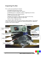
Unpacking The Box
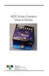
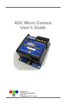
This is what you should find in the box.
A Hardened Plastic Camera Case
An MCA or MiniMCA Digital Still Camera
A CDROM with the installation software supporting the camera
Product and Accessory Documentation
A USB interconnection cable
Compact Flash Memory Cards for each camera in the array
An AC Power Adapter and Power input cable
A White Teflon Calibration Plate
Your camera comes with a one-year warranty against defects. You should
send in the warranty card to register the camera and qualify for additional
software and firmware updates.
Documentation
Teflon Calibration
Plate
Installation
Software CD
Power Adapters
MiniMCA Digital
Still Camera
USB Cable
Power input cable
Figure 1 - Contents of the Shipping Box
Control Cable
Cards
.
Page 4
Multi-Camera Array User's Guide
Getting Started
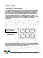
Overview of the MCA System
The MCA imaging system consists of a set of digital still cameras compactly
packaged and synchronized so they can all take pictures at the same time
with only small translation errors between images from unit to unit. These
translation errors are automatically corrected by the software supplied with
the unit.
One of the cameras in the system is set up as the MASTER camera – the
master camera is responsible for synchronizing the other cameras (SLAVES),
calculating exposure requirements, and logging GPS geo-referencing
information.
A control connector (and control box accessory) is provided to allow the
camera to be triggered in flight, and to provide connection to an external GPS
receiver. The control connector also has an output video signal that can be
used to monitor the framing of the image. Monitoring can take place remotely,
using a commonly available video transmitter for RC aircraft, or locally, in a
manned aircraft, using a video monitor.
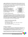
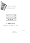
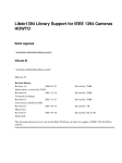
Each camera has its own file system for saving images. In a six-camera
6 Channel Mini MCA
Lens / filter layout
USB Connector
system there will be six compact flash cards installed in the unit. Each will
have a unique volume ID and naming convention for images that allows the
sets of pictures to be separated on the host PC. The software supplied with
the camera automatically combines the images into multi-channel TIFF image
file for convenient extraction of the data at any time.
Each camera has its own band pass filter – typically a spectroscope filter
commercially available from companies like Andover or Sigma. A wide variety
of pass filters are available. Bandwidths of 10 nanometers and above will
Multi-Camera Array User's Guide
Page 5
supply acceptable images. Narrower band pass filters (less than 10 nm) can
produce some artifacts in the images which must be corrected on the host
PC. Band pass filters may be anywhere in the range of 400 nm (blue) to 950
nm (near infrared). The spectral response graph later in this document shows
the working range of the sensors. A set
of six filters is ordinarily specified at the
time of purchase.
Images can be transferred to a host
PC by removing and reading the
memory cards, or by plugging in a
USB cable to the USB Hub controller
built into the unit. In a six-channel unit,
six separate devices will appear when
the unit is connected.
PC System Requirements
Any IBM-compatible personal computer with a free USB serial jack can be
used to operate and configure the Camera. The unit produces sets of images
synchronized for simultaneous capture. The images from the set can be
displayed three channels at a time using RGB format for false color rendition.
Each RGB rendering is about 3.9 Megabytes. You should select a computer
with resources that can support manipulation of images that are this large.
Our recommendations for a minimum configuration are:
1 GHz or better processor, Intel or AMD
Windows 7, Vista or XP operating system
512 megabytes of SDRAM
24 bit color graphics adapter at 1024 x 768 or better resolution
1024 x 768 or higher display
Large hard disk drive with 10 GB or more free space
Software Installation
The software installation CD contains PixelWrench2, the USB stream driver
and a PDF version of the user’s manual. To install PW2, run the file
Setup.exe located in the PW2 folder. The root folder of the CD also contains
the image alignment file for your particular camera. Its name is
xxxxxx_global.MCA where xxxxxx represents your camera serial number.
If you have not previously used a digital camera on your system, the
Windows operating system may need to install some additional files to
Page 6
Multi-Camera Array User's Guide
support the camera drivers.
If your computer does not have the Microsoft .NET 3.5 framework installed,
the PixelWrench2 installer will try to open Microsoft.com and download a file
called dotNetfx.exe. This is the installer for .NET 3.5. This file is also on the
CD in the root directory where you can run it directly prior to installing
PixelWrench2.
Hardware Installation
The MCA and Mini MCA
run nominally on 12VDC
external power. The
input has been designed
for vehicle electrical
systems and can handle
input voltages as high as
14 volts. The power
connectors are center
positive.
The MCA and Mini MCA
differ primarily in their
optical capabilities and weight. The older MCA product supports replaceable
C-Mount lenses with variable aperture controls to match filter characteristics.
The mini MCA is designed for UAV applications, and weighs only 25% the
original MCA weight. It uses smaller miniature lenses with fixed apertures.
Filter characteristics are calibrated into the camera firmware in the mini MCA.
The optics on the standard MCA are better suited to very narrow band pass
filters.
The MCA camera has a variety of connectors, as
shown in the illustrations. The mini MCA has
only a power connector and multifunction control
connector available on the external case. All of
the signals on separate connectors, including
power are available on the multifunction
connector. In the discussion of interconnection
signals that follows, the signals may be found on
the multifunction connector, and also in the case
of the standard MCA, on the separate connectors
provided.
Multi-Camera Array User's Guide
Power Connector
Multifunction
Page 7
Camera Interconnections
Power – 12VDC center positive supply capable of delivering 0.5 Amps
continuous. The supplied wall-plug type supply connects to this jack
USB – The main USB I/O connector (behind access panel on MiniMCA)
Multi I/O – 16-pin connection to the Camera Controller for viewing video,
navigating the menu, taking pictures, and connecting GPS
Video Out – (Camera Controller ) NTSC or PAL video signal
RS-232 – (Camera Controller ) For connecting an optional GPS receiver or
sending commands to the camera. A 3.5mm stereo phone plug tip, ring and
sleeve is camera receive, camera transmit, and ground, respectively.
MCA Optics and Filters
All channels of the MCA must be equipped with the same type of lens so the
images can be merged with a minimum of error and distortion. Each channel
has a receptacle for a spectrometer filter. The filters can be obtained from a
commercial supplier, such as Andover. The unit is supplied with a set of six
filters as specified by the customer at the time the unit is ordered.
Changing filters or installing them for the first time requires that the exposure
time for each channel by adjusted for the filter characteristics. In the standard
MCA, the adjustment can be made by setting the apertures on the lenses, or
by entering exposure constants for each channel. In the mini MCA, only the
second technique is used, since the apertures in the mini MCA lenses are
fixed.
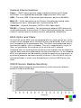
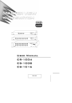
CMOS Sensor Relative Sensitivity
The graph below shows the relative efficiency of the sensor for different
bands of visible and NIR light.
Page 8
Multi-Camera Array User's Guide
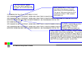
The Calibration Image
An important part of the entire camera and software system is the need to
calibrate the software supplied with the camera. Calibration consists of taking
an image of the Software Calibration Tile under the same lighting conditions as
the images under study. This image is used to teach the application software
what the spectral balance of that day's sunlight is. The ratio of red/NIR or
green/NIR is then applied as an offset to the calculation of the various
vegetation indices. Note: if a calibration image is not taken within an hour or
two of pictures in the field, the vegetation index calculations will not be very
accurate, and the pictures may not be
useful.
Place the Software Calibration Tile on
the ground, or hold it level to ground,
and photograph it. It need not fill the
entire frame and it must not be
overexposed. Make sure to avoid a
direct reflection of the sun. The sample
image on the left is of a properly
exposed Software Calibration Tile.
When the pictures are imported to the
host computer, the calibration image
will be used to refine the vegetation
index calculations.
Software Calibration Tile Image
Compact Flash Cards
The unit can handle Compact Flash (CF) cards up to 2 GB. Since stored
images are about 1 megabyte each, a 512 megabyte card is the minimum
capacity recommended. A set of 2 GB cards (one per channel) is supplied
with the unit.
Note: The unit cannot take pictures without a compact flash cards installed.
We recommend that the unit's power be turned off when the compact flash
card is replaced. CF cards manufactured by SanDisk have proven the most
reliable in our testing of the unit.
The camera is usually operated away from the host computer. If a compact
flash memory reader is present on the host computer, the software can
extract images directly from the card, without having to connect the camera.
This allows the camera to be left in the field, or attached to a vehicle. The CF
cards are exchanged to bring the pictures to a host computer.
When CF cards with capacities in excess of 2 Gigabytes are used they must
Multi-Camera Array User's Guide
Page 9
be formatted as FAT32 cards on the PC, because the camera is not capable
of initializing CF cards to FAT32 format. Care must be taken to label the
volume TTCDISK[1-8], as it comes from the factory, during formatting on the
PC. Also format the card using 32kb cluster (allocation unit) size for faster
camera boot times. The volume information is used by PixelWrench2 to
identify the device as a Tetracam camera, and identify the channels when it
appears as a USB Disk. While reliable, use of very large cards with FAT32
format is not recommended unless very long missions with many pictures
require it.
Camera Controller
The camera controller is used to setup and manually control the camera. The
controller has two connectors on its side: an RCA jack for video out to a TV or
monitor and a 3.5mm phone jack for serial RS-232 connection to a GPS
receiver. On the bottom of the controller is the 16-pin connection to the
camera. At power up, a connected TV or monitor display will illuminate and
begin displaying the live viewfinder image.
Controlling the Viewfinder
In daylight conditions, a properly set exposure will produce a fairly dim
viewfinder image so that NIR data is not over-exposed. For certain pictures it
may be useful to adjust the exposure using the UP and DOWN buttons.
When in auto-expose mode, pressing the UP or DOWN buttons will increase
or decrease the exposure by 1/6 f-stop for each press. When in fixed expose
mode, pressing the UP or DOWN buttons will increase or decrease the
exposure time by ½ millisecond for each press.
Once the viewfinder image is satisfactory, capture can be initiated with the
TAKE PIC button on the controller. The Status LED will turn from green to
red, indicating that the camera is busy capturing and saving the image. After
a capture, the camera completes the compression and storage of the image
and the status LED returns to green indicating the camera is ready.
Page 10
Multi-Camera Array User's Guide
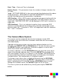
The Camera Viewfinder
Once the camera is powered on, after a few moments it finishes its initial
bootup sequence and enters viewfinder mode where it is ready for image
captures. This is the normal ready-state of the camera. From this state, the
use may adjust the exposure time up or down, using the UP or DOWN
buttons, enter the menu system using the MENU / SELECT button, or
capture images using the TAKE PIC button.
With an external video monitor connected to the camera’s video out port, a
live video image of what the camera “sees” will be shown on the screen. An
overlay of information is shown on the viewfinder by default and can be
turned off in the camera’s menu. Below are shown the different points of
information, arranged as shown on the viewfinder screen, with descriptions
for each.
USB Mode – USB DISK MODE will be displayed if the camera is set to
enumerate as a USB DISK when connected to a Windows computer via USB.
Save Mode – Displays DCM, R8, or R10 for the type of image the camera is
set to save. DCM is a compressed 10-bit format, while R8 and R10 are 8-bit
and 10-bit RAW file formats, respectively.
Cont. Capture – This parameter is displayed in green when Continuous
Capture is enabled, and in red when capturing, and shows the amount of
Continuous Capture delay set.
Exposure Mode – If a FIXED EXPOSURE is set, this parameter will display
the word “FIXED” in red along with the set exposure time, in milliseconds.
With Fixed Exposure turned OFF, this parameter will display “AUTO A” or
“AUTO P”. The “A” or “P” designation indicates the METHOD of Auto
Exposure, Average or Peak. A positive or negative number may follow this
parameter, indicating the Exposure Adjust setting, controlled by the UP or
DOWN buttons from the viewfinder.
Multi-Camera Array User's Guide
Page 11
Date / Time – Date and Time is displayed.
Picture Count – This parameter shows the number of images stored on the
CF card.
*note: SETTINGS DISPLAY in the menu controls the displaying of the above
listed parameters. GPS DISPLAY and GPS HEARTBEAT in the menu
controls the displaying of the parameters listed below.
GPS Position – With a GPS receiver connected and communicating with the
camera, position coordinates will be displayed. If the GPS receiver loses its
signal lock, “WAITING FOR GPS” will be displayed in RED until it recovers its
signal lock.
GPS Heartbeat – This is an indicator to confirm that a connected GPS
receiver is sending data to the camera. Every time the camera gets a new
packet of data, the “/” character in “GPS/” will toggle back and forth, between
the “\” and “/” characters.
The Camera Menu System
The camera can be configured from the host computer via the USB
connection or by use of the menu selections accessible with the controller
and video display.
Operation of the menu system uses the three rightmost buttons on the
controller: the SELECT, UP and DOWN buttons. To enter the menu system,
the SELECT button is pressed once. Sub menus appear, or menu items
which have values to the right of them.
To select a submenu, use the UP/DOWN buttons to move the cursor up or
down to the desired submenu entry. Press the SELECT key to display the
next menu page in the tree. If a submenu is not available, (REVIEW cannot
be accessed unless pictures have been taken) it will be gray in the display
instead of white. The selected entry is hi-lighted in green.
To change a menu item value, navigate to it by pressing the UP/DOWN
buttons, and select it by pressing SELECT. The menu item’s value will turn
green, indicating that it is selected. Use the UP/DOWN buttons to scroll
through the available values, and SELECT again to set the value.
The menu system can be exited at any time by pressing the TAKE PIC
button.
Page 12
Multi-Camera Array User's Guide
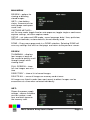
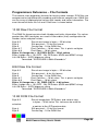
MAIN MENU
REVIEW – options for
viewing or deleting
stored images.
INFO – view battery
status, firmware version
and storage card space
used / free.
CAPTURE METHOD –
set file save mode, toggle fixed or auto exposure, toggle single or continuous
capture settings, set alarm capture mode.
SETUP – set video and USB mode, menu language, date / time, quickview,
GPS and viewfinder, restore defaults, format memory card.
DONE – Every menu page ends in a DONE selection. Selecting DONE will
save any settings that exist on that page and return to the previous screen.
REVIEW
THUMBNAIL – displays
four images at once on
the screen to quickly scroll
through images while
viewing them.
FULL SCREEN – show
full size images one at a
time
DIRECTORY – show a list of saved images
DELETE ALL – erase all images on memory card at once
All images are listed in order from most recent to oldest. Images can be
erased one at a time when selected individually.
INFO
Shows the power supply
voltage, camera firmware
version number, used,
free, and total space on
the memory card.
Multi-Camera Array User's Guide
Page 13
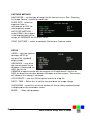
CAPTURE METHOD
SAVE MODE – set the type of image file the camera saves. See “Choosing
An Image Format” section for more help.
FIXED EXP – select an
exposure time in
milliseconds or OFF for
auto-exposure mode.
AUTO EXP METHOD –
select PEAK if the subject
is the brightest part of the
image, or AVERAGE for all others cases.
CONT CAPTURE – select to configure Continuous Capture mode.
SETUP
VIDEO – sets the camera
to output NTSC or
various PAL standard
display feeds.
USB MODE – sets what
the camera looks like to
Windows if connected via
USB. Set this to
CAMERA to communicate with the camera via PixelWrench2. Set this to
DISK for direct file transfers between Windows and the camera. The camera
will reboot if this setting is changed.
LOG EVENTS – turn this ON to capture events to a log file.
DATE / TIME – Select this to set the time and date for image stamps.
QUICKVIEW – select this to set the amount of time a newly captured image
is displayed on the viewfinder screen.
MORE… – More setup options
Page 14
Multi-Camera Array User's Guide
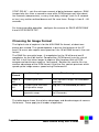
MORE…
LANGUAGE – Set the
menu language.
GPS BAUD – Set the
serial connection data
rate between the camera
and a GPS receiver.
GPS HEARTBEAT –
When ON, an indicator is shown on the viewfinder screen, signaling each
time the camera receives information from the GPS receiver.
GPS DISPLAY – When ON, GPS coordinates are displayed on the viewfinder
screen.
SETTINGS DISPLAY – Toggles the display of settings information on the
viewfinder screen, such as exposure, files save type, picture count, etc.
FORMAT CF CARD – select this option to re-format the CF card.
RESTORE DEFAULTS –
select this option to
return all settings to
factory defaults. This is
recommended any time
the camera’s firmware is
upgraded.
Continuous Capture Mode
This mode of operation causes the camera to begin taking pictures when the
TAKE PIC button is pressed, and to continue taking pictures until the button
is pressed again. It is the simplest way to operate the camera on a remote
aerial vehicle. The rate of capture is controlled by the file format selected, and
the additional delay set between pictures.
CONT CAPTURE – turns
Continuous Capture
mode ON or OFF
Multi-Camera Array User's Guide
Page 15
CONT DELAY – sets the minimum amount of delay between captures. RAW
images take less than a second to save while DCM images may take about
five seconds (compression), so very short delay settings (such as 5 seconds
or less) may not be realized because of file save times. Range is from 0 – 60
seconds.
For fastest possible operation , configure the camera for SAVE MODE RAW
8 and LOG EVENTS OFF.
Choosing An Image Format
The highest rate of capture is for the 8 Bit RAW file format, at about one
picture per second. The speed depends in part on the features of the CF
card. For users who require more precision, the 10 bit RAW format is the next
fastest.
The RAW files are quite large – 6 megabytes for the 10 bit format and 3
megabytes for the 8 bit format. Compression (DCM format) cuts the size of
the files in half, but takes longer to capture. We therefore think of DCM
compressed continuous mode as “low speed”. Besides the smaller file size,
another advantage of the DCM format is that the files contain previews which
speed up the image access speed using Pixelwrench2.
File
Format
-----Advantages-----------
----------Disadvantages---------
RAW 8
bit
Fastest cycle time
Less dynamic range, no embedded
previews
RAW 10
bit
Fastest cycle time with
full dynamic range
Big files, no embedded previews
DCM 10
Smallest file size with full
dynamic range
Longest time between pictures (up
to 5 seconds)
The table above shows the relative advantages and disadvantages of camera
file formats. These apply to all modes of operation.
Page 16
Multi-Camera Array User's Guide
GPS Option Installation and Use
Your MCA will capture and append the most recent GPS data string to each
image as it is taken. The following requirements apply; Your GPS receiver
must be configured to output the standard NMEA RMC and/or GGA
sentences. The default output protocol for NMEA sentences is 4800 baud, 8
data bits, 1 stop bit, no parity. Your receiver should allow you to configure it
for RMC and/or GGA at 4800:8:1:N. If your GPS receiver can be configured
for a higher Baud, you should take advantage of the feature, since it will
make the GPS data more accurate since less time would be lost transferring
the messages. The menu in the camera has an entry for the GPS Baud.
There is also an advanced setup screen, accessible via Pixelwrench2 that
save a higher baud rate.
The GGA sentence is emitted once per second and contains the following
fields:
1.
Time UTC
2.
Latitude and Longitude
3.
Fix quality
4.
Number of satellites tracked
5.
Horizontal dilution of position
6.
Altitude in meters MS
7.
Height above MSL
Attach the optional serial cable to the small serial connector (see the
illustration in the Hardware Installation section of this manual). Attach the
other end to the serial port of the receiver.
The most recent GPS sentence sent to the camera will be appended to the
image data file. You can view the GPS data in the image using Pixelwrench2.
The camera firmware also supports an event, or position, logging system that
will exactly place the GPS locations at the time pictures are taken, with a
resolution of 10 milliseconds.
The camera also has two features you can turn on in the setup called GPS
HEARTBEAT and GPS DISPLAY, which will toggle an indicator on the
viewfinder screen each time it receives a new GPS sentence and will show
the last GPS position received. This is useful to see that the camera is
properly receiving GPS data.
Multi-Camera Array User's Guide
Page 17
Event Log File
When LOG EVENTS is set to ON in the CAPTURE METHOD screen, The
camera will maintain a file with a record of key events that can be used to
accurately position the location at which the picture was taken. Generally, a
GPS receiver is connected to the camera serial port that sends $GGA… and
$RMC…position strings to the camera.
This feature is used most often with aerial photography, when the GPS point
is directly below the camera, so that both the camera and the image are at
the same coordinate.
When the option is enabled, the camera creates the file CURRENT.LOG on
the CF memory card in root folder. If there is a pre-existing CURRENT.LOG
file, the file is moved to the image folder (TTCMCA0 in the case of the MCA
master camera) and renamed according to the image numbers that were
captured while the camera was last in operation. Only the master camera
channel logs GPS data and image events.
For Example: If images 31, 32, 33, and 34 were captured, there will be event
log records for each of those captures in the file. The file is scanned image
capture records, and the smallest and largest image numbers found are used
to compose a file name. In this case, the file would be renamed to
00310034.LOG. The first four characters of the new file name are the lowest
image capture record in the file; the second four letters are the highest image
capture record in the file.
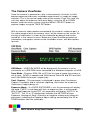
A typical Event Log file is shown on the next page. Each line shown is one
record in the file, terminated by a newline character and NULL. The NULL
characters are hidden, and additional line feeds are added for clarity in the
illustration.
Log files are much easier to manage if the camera is set up to operate in the
USB Disk mode described earlier. The Log files are not directly accessible
from Pixelwrench2 using the stream interface. When the camera shows up as
a folder window on the desktop, as it does in USB Disk mode, the moving
and deleting files is trivial.
You can use the GPS Distiller tool to manage image and GPS log files. See
the PW2 help file for more information on how PW2 uses the distilled log files
to refine the embedded GPS data in each image.
Remember, you can switch the camera between being recognized by
Windows as a USB MASS STORAGE DEVICE and an IMAGING DEVICE
(USB Disk Mode vs. able to connect to PixelWrench2) by holding the
SELECT button down for five seconds during power up.
Page 18
Multi-Camera Array User's Guide
The CLK record is added
when the camera powers up.
It shows the camera date and
time.
Every Record has a “Ticks” Field
that shows the cameras internal
clock count of 10 millisecond ticks.
The count 104 means that che CLK
record was written 1.040 seconds
CLK 000000104 Date/Time: 10/22/2009 15:15:01
after power on.
GPS 000002006 00217 $GPRMC,192254.00,A,2942.79012,N,08223.30667,W,000.0,000.0,221009,03.3,W,A*0B
GPS 000002064 00217 $GPRMC,192254.00,A,2942.79012,N,08223.30667,W,000.0,000.0,221009,03.3,W,A*0B
$GPGGA,192255.00,2942.79047,N,08223.30663,W,1,04,2.58,00040,M,-031,M,,*5D
IMG 000003049 00218
If a GPS is connected, an entry
GPS 000003102 00218 $GPRMC,192302.00,A,2942.79461,N,08223.30899,W,000.0,000.0,221009,033,W,A*06
is made each time a GPS
update string is received.
GPS 000003280 00219 $GPRMC,192302.00,A,2942.79461,N,08223.30899,W,000.0,000.0,221009,033,W,A*06
Different GPS messages are
$GPGGA,192303.00,2942.79517,N,08223.30922,W,1,04,2.58,00062,M,-031,M,,*55
concatenated as they come in
When a picture is taken, a record is written showing the
system ticks at the end of integration. The camera can only
do one thing at a time, so there will always be a system ticks
offset between capturing a picture and the GPS messages.
The actual position of the camera when the picture is
captured can be approximated by interpolating between the
two GPS messages using the system ticks.
Multi-Camera Array User's Guide
Page 19
Host Software
The software supplied on the installation CD is made of several major
components:
1. An image acquisition and manipulation application, named Pixelwrench2
2. An optional GPS guided camera trigger application named SensorLink
3. A camera interface DLL for extracting images from the camera or CF
card, and converting them to Windows DIB format for display.
The goal of this software is to allow the user to extract the Blue/ Green /Red
false color images from the captured image set so that band radiation can be
visibly displayed regardless of where in the spectrum (NIR / visible) it may lie.
PixelWrench2
PixelWrench2 (PW2) is a powerful image editing program with several tools
specific to multi-spectral images and working with Tetracam ADC and MCA
cameras. Open the PW2 folder and run Setup.Exe. This will install
PixelWrench2. See the PixelWrench2 online help for more information.
PW2 can open MCA proprietary DCM10, RAW10 and RAW8 image files
along with several standard image file types (BMP, JPEG, TIF, PNG etc.)
If you purchased the optional SensorLink application you will find a folder by
that name on the CDROM included with the camera.
SensorLink
SensorLink is a GPS waypoint triggering application enabling camera
triggering at pre-defined waypoints. It uses the same .NET 2.0 framework.
Simply run Setup.exe in the SensorLink folder to install it. See the SensorLink
online help for more information.
Connecting The Camera For Driver Installation
With the camera powered up and USB MODE set to CAMERA, connect the
USB cable from a working USB port on the computer to the connector labeled
USB on the camera interconnect panel.
On Windows XP systems, the first time the camera is connected to a USB
port, Windows will launch the New Hardware Found wizard. This will guide
you through installation of the camera driver called SvStream.sys. If you plan
to operate the camera as a USB Disk, skip to the next section.
Do not let Windows search for the driver. In every case select the option
where you specify the name and location of the driver. The driver
SvStream.sys and its information file SvStream.inf will be copied to your
Windows/System32/Drivers folder when you install either PixelWrench2 or
Page 20
Multi-Camera Array User's Guide
SensorLink. When the driver installation wizard asks for a location, browse to
Windows/System32/Drivers.
In both PixelWrench2 and SensorLink, you are required to specify the camera
type prior to accessing the camera. In PixelWrench2, on the Camera Toolbar,
click the small down arrow on the top button (Status). Select MCA as your
camera type. This loads the correct DLL for use with the MCA. See the
PixelWrench2 online help file for further specifics on camera communications.
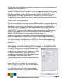
USB Disk Configuration:
With the introduction of firmware version 5.097 the MCA can be configured to
appear as a USB disk drive to the operating system. For Windows Vista, or
operating systems other than Microsoft, the camera must be operated as a
USB Disk device. To toggle the USB mode between DISK and CAMERA,
change the USB MODE setting in the camera’s menu SETUP page and then
select DONE – the camera will reboot automatically with the new mode set.
You can also toggle the USB MODE setting by simply holding down the
MENU / SELECT button for a few seconds during power up.
However the camera is configured, it will be recognized by Pixelwrench2
when that application is started. In the original stream mode of operation,
Pixelwrench2 is the only way to exchange data with the camera over a USB
link. When the unit is configured as a USB Disk, files can be dragged and
dropped to and from the camera from any personal computer that has USB
disk drivers.
Managing and Processing MCA Images in PixelWrench2
The MCA system writes losslessly compressed
image files or RAW files to the CF card for every
image. These images carry the extension *.DCM
or *.RAW. PixelWrench2 offers all the tools
needed for management of MCA images located
on the pages of the IndexTools form.
There are four ways to retrieve images from the
MCA;
1. Remove the CF card from the camera and
copy its contents to a folder on your computer.
The *.DCM and *.RAW files can then be opened
directly in PixelWrench2.
2. In PixelWrench2; open the camera toolbar
then click Open Camera. The camera inventory
screen will appear with thumbnails of all the
Multi-Camera Array User's Guide
Page 21
images. Select an image (or images) then click Load. The image(s) will be
extracted from the camera, color processed using the matrix values entered
and stored by the DLL and displayed on screen as an RGB dib.
3. Power up the camera in USB disk mode and open *.DCM or *.RAW files
directly using PW2.
4. Transfer all the files to the PC, and open them with Pixelwrench2 after they
are on the hard disk.
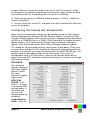
Configuring the Camera with Pixelwrench2
Many camera configuration settings can be modified using the Edit Camera
Settings dialog accessed from the PW2 Camera Toolbar. To open the Edit
Camera Settings dialog, make sure the camera is powered up and connected
to USB as a CAMERA (not as a DISK). Click Status:ADC to enable the other
toolbar buttons. Click Setup and the Setup Camera Attributes dialog will
appear. Click Advanced and the Edit Camera Settings dialog will appear.
This dialog on the next page contains two columns of edit boxes. Place your
cursor over an edit box to view a tooltip describing the setting parameters for
that box. In the figure, the cursor was placed over the SAVE MODE box. The
tooltip shows the possible settings for file save mode. This camera is
configured to save in DPCM lossless. Many of the settings boxes do not
apply to how the ADC should be configured and there is no reason to change
the existing settings.
GPS BAUD –
Sets the baud
rate for capture of
GPS data. NMEA
default is 4800
but some
receivers support
higher rates.
NTSC PAL
STATE – 0 for
NTSC, 1 through
4 for several PAL
configurations, 5
to disable and
use the LCD
(default power up
condition).
Image Number
Index – Sets the
Page 22
Multi-Camera Array User's Guide
number that will be applied to the next image taken, then auto increments as
images accumulate. Can be set to any positive value or 0.
SAVE MODE – Sets the file format that images are saved in. The ADC
should save in DCM, RAW 10 or RAW 8 (1, 2 or 3, respectively).
FIXED EXPOSURE – Allows presetting a fixed exposure. The value is
entered in microseconds. Enter 0 to set the camera to Auto Exposure mode.
AUTO EXPOSE – Sets the method of Auto Exposure Mode, Average or Peak
The 16-Pin Multi I/O Connector
The following describes the 15-pin functions of the Multi I/O connector:
1 – supply power
2, 3, 4 & 5 – MENU/SELECT, UP, DOWN, and TAKE PIC buttons,
respectively. Momentarily short to ground for button activation.
6 – power switch / external event trigger
7 – RS-232 Transmit (GPS)
8 – RS-232 Receive (GPS)
9 – Red LED: logic high when camera is busy
10 – Green LED: logic high when camera is on / idle
11 – (NC)
12, 13 – NTSC or PAL video signal and ground, respectively
14 – 3.3 V (logic high)
15 – ground
16 – (NC)
Mounting the unit
The four ¼” holes in the top flange of the standard MCA camera housing are
there to accept mounting bolts. In the case of the MiniMCA, the four
fasteners that attach the bottom plate to the blue case should be used. It is
always advisable to provide vibration isolation between the camera and
aircraft. Additionally make sure to ground the camera using to the mount. If
the camera is mounted on non-conducting vibration isolators a ground strap
should be provided. Dress and restrain all interconnect cables to prevent
snagging or undue disturbance by prop blast etc. The MCA camera housing
and optics are not weatherproof. If the camera is mounted externally, weather
protection should be provided
See the dimensional illustration in the Specification section for additional
details.
Multi-Camera Array User's Guide
Page 23
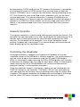
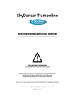
Capture Delays for Aerial Photography
The simplest way to map large areas is to place the camera in Continuous
Capture mode with a delay that will ensure adequate overlap of the images.
Since picture storage is cheap, 30 to 50% overlap is recommended. In order
to calculate the delay, the cruise speed of the aircraft and altitude above the
ground must be known. For example:
Using the standard 8.5mm focal length lens, at 2500 feet AGL the camera
captures 1/2 meter per pixel, or 1.28 kilometers along the long axis. If
approximately 30% overlap is desired, we would take pictures every 450
meters. If the aircraft is traveling at 180 km/hour or 50 m/sec, the time to
cover 450 meters is nine seconds. We would, therefore, set the Continuous
Capture delay to nine seconds or less.
Increasing the altitude above the ground increases the delay needed while
reducing the ground resolution of the images. At 5000 feet AGL, the camera
resolution is approximately 1 pixel per meter, which is good enough for many
crop surveys. At this altitude the required delay is doubled.
Aircraft forward speed 180
km / hr or 50 m / sec
Altitude:
640 meters
of ground
coverage
2500 feet
AGL
The captured images can be easily assembled into a mosaic by stitching
software. Autopano Pro does a fast and accurate job of building a mosaic
from separate images. We recommend that the images be processed first
into the color space needed for analysis - palletized NDVI, or false color NIR,
for example. PixelWrench2 can do this quickly, using its built in batch
function.
Page 24
Multi-Camera Array User's Guide
Programmers Reference – File Formats
The camera uses proprietary formats for lossless data storage. DCM files are
compressed using differential encoding and Huffman compression. RAW files
are the array of captured pixel values with header and trailer information. The
exact format of these file in 8 and 10 bit form is shown below.
10 Bit Raw File Format
The RAW file format contains both Header and trailer information. For values
greater than 255, two bytes are used in little endian (Intel) configuration for
header, trailer and pixel values.
Byte 0-3
Size of raw image in bytes – 32 bit value
Byte 4
Bits per pixel – 10 for this format
Byte 5
Format tag – 16 for RAW files
Bytes 6-7
Pixel Columns – 16 bit value. This is pixels not bytes
Bytes 8-9
Pixel Rows – 16 bit values
Bytes 10-(image size + 10) PIXEL DATA – 16 bit values
Bytes (image size + 10)-(EOF - 28) GPS data. $GGA and $RMC strings
Last 28 Bytes – ASCII exposure string
formatted: "EXPOSURE:%08ld uSeconds\n"
8 Bit Raw File Format
Byte 0-3
Size of raw image in bytes – 32 bit value
Byte 4
Bits per pixel – 8 for this format
Byte 5
Format tag – 16 for RAW files
Bytes 6-7
Pixel Columns – 16 bit value. This is pixels not bytes
Bytes 8-9
Pixel Rows – 16 bit values
Bytes 10-(image size + 10) PIXEL DATA – 8 bit values
Bytes (image size + 10)-(EOF - 28) GPS data. $GGA and $RMC strings
Last 28 Bytes – ASCII exposure string
formatted: "EXPOSURE:%08ld uSeconds\n"
10 Bit DCM File Format
Byte 0-3
Size of image data, GPS data, and various tags
in bytes – 32 bit value This value can be used to
calculate
Byte 4
Byte 5
a pointer to the JPG preview data
Bits per pixel – 10 for this format
Format tag – 16 for RAW files
Multi-Camera Array User's Guide
Page 25
Bytes 6-7
Pixel Columns – 16 bit value. This is pixels not bytes
Bytes 8-9
Pixel Rows – 16 bit values
Bytes 10-(data size + 10) DATA – 8 bit values
Bytes (data size+10)-EOF JPEG Preview image.
Looking backwards into the data encompassed by the size value in the header there
are several fixed length fields, given below with their sizes.
GPS data – 1024 Bytes
Tags for temperature and clock ticks – 16 bytes
We do not recommend trying to process the DCM files with your own code. Contact
Tetracam for assistance with sample ‘C’ source files if reading the DCM file data is
absolutely necessary.
Programmer’s Reference – C and Visual Basic
Support
The interface to the camera is in the library SXGAMCA.DLL This library
provides a number of useful camera interface functions. Developers, to
incorporate the camera interface into their own programs and plug-ins, can
use the interface functions embedded here. The file sxgaMCA.lib is provided
in the installation directory to allow static linking to the DLL.
The “include” file loadext.h is available in the installation directory to be made
part of any C or C++ program making use of the DLL. It is reprinted in part
below. All requests are made by filling the PixRequest structure before the
function is called. Sample source files are available from Tetracam to help
with the creation of a custom application.
typedef struct _PXR
{
int requestType;
int workSilently;
int imageNumber;
char far *fileName;
int imageBlue;
int imageGreen;
char far *statusString;
// ACTION type
// do not pop up status or hourglass the cursor
// 0 = last image in camera or file
// 0000:0000 = use camera - Otherwise the file to open
// "" = ask userask user for file name
// "xxxx" = use file xxxx.DCA for reading
// Used for various arguments
// Used for various arguments
// copy camera/image status string to here
// if not 0000:0000
} PixRequest;
In Visual Basic a wrapper function is provided which accepts the values
passed in as individual variables. It then creates the required structure before
calling ProgrammerPlug(). A sample calling sequence from Visual Basic is
shown below the interface function definition:
Page 26
Multi-Camera Array User's Guide
TTCAM_API HANDLE VBProgrammerPlug
(
int FAR *requestType,
int FAR *workSilently,
int FAR *imageNumber,
char FAR *fileName,
int FAR *imageBlue,
int FAR *imageGreen,
char FAR *statusString
);
/* Here is what a call looks like made from Visual Basic into the DLL:
Declare Function VBProgrammerPlug% Lib "SXGAMCA"
(
requestType%,
workSilently%,
imageNumber%,
fileName as Any,
imageBlue%,
imageGreen%,
statusString as Any
)
For integers, According to the VB manual for version 1.0 or thereabouts,
VB passes, by default, all arguments by reference, (or far pointers,
if your a 'C' programmer. ByVal overrides this by placing the contents
of the variable on the stack, rather than the pointer to the variable.
For strings, It appears the ByVal is the way to point to a string that is
to be modified by the DLL. The examples in the book for calling Windows
APIs that modify strings show a declaration as ByVal. See the chapter
headed "Calling DLL Routines with Specific Data Types" for details.
To pass a NULL pointer to VBProgrammerPlug, use ByVal 0& as the
parameter for fileName or statusString. To pass a pointer to a fixed length
string, use the syntax ByVal StringName$ in the argument list.
*/
The Visual Basic call ends up here after translation of the calling parameters into a PixRequest Structure
TTCAM_API HANDLE PASCAL ProgrammerPlug(PixRequest FAR *);
/******* Multifunction DLL interface *********************************
IMPORTANT
The caller must always use the HOOKUP request before any other reqests are made!!!!
Passed a pointer to a request block this function will perform the
requested action, (see enumerated list, below) and return either the state
of the current hookup, a handle to a DIB image, or the camera or file
status string. After processing any image controlled by the DIB handle
returned, you are responsible for freeing the memory controlled by the
DIB's handle BEFORE calling ProgrammerPlug for another image.
*/
enum {HOOKUP = 0,
// Hook up to the camera/file and prepare DLL to
// load images in following calls.
Multi-Camera Array User's Guide
Page 27
// if fileName = 0000:0000, use the camera
// if fileName = "xxxxx" or "xxxx.xxx", use file
// if fileName = "" or "*", prompt user for file name
// RETURNED PixRequest values:
//
requestType = COLOR or GRAYSCALE
//
depending on camera or file type
// imageNumber set to # of images available
//
//
requestType and imageNumber are both set
// to 0 if a file or camera I/O error occured
// If a non-NULL pointer is found in statusString,
// the camera or file status string is copied. a ""
// is returned if there was an error.
STAMP = 1,
// return a handle to the STAMP DIB
// RETURNED PixRequest values:
// HANDLE to a D)evice I)ndependant B)itap, (DIB)
// requestType = COLOR or GRAYSCALE depending on
// what picture type the stamp represents
// Returns a 0 on error
GETIMAGE = 2, // standard gray scale image
// RETURNED PixRequest values:
// HANDLE to a DIB
// Returns a 0 on error
CAPTUREBUFFER = 7,
CAMERASTATUS = 8,
IMAGESTATUS = 9,
// Returns the camera's image capture buffer
// as a DIB. Stretch, sharpen and scale
// are also done.
// CALL WITH:
// imageNumber = image type to return
// RETURNED PixRequest values:
// HANDLE to a DIB
// returns NULL on error
// Send the camera status string
// RETURNS:
// Camera status string copied to statusString.
// Returns "" on error
// Send the imageNumber status string to
// RETURNS:
// Image #imageNumber status copied to statuString
// Returns "" on error
SETEXPOSURE = 10, // Send the value in Blue (LSW) and Green (MSW)
// to camera as exposure time. 0=automatic,
MULTISELECT = 16, // Allow Operator to Selecting Multiple Images
// CALL WITH:
// imageNumber = Number of images pre-selected
// statusString= pointer to NULL terminated byte
Page 28
Multi-Camera Array User's Guide
SNAPSHOT = 17,
//
array containing the ID numbers of
//
images to pre-select, in the order
//
desired.
//
ARRAY SPACE MUST BE AT LEAST
//
57 BYTES!!
// imageGreen = Maximum number of images allowed
//
to be selected. If 0, the max
//
is the number of images in the
//
file/camera.
// imageBlue = TRUE=Show selection order number
//
in stamp upper left corner.
//
FALSE= No selection Number.
// RETURNED PixRequest values:
// imageNumber = Number of images selected, or
//
zero if none or error
// statusString= pointer to NULL terminated byte
//
array containing the ID numbers of
//
operator selected images in the
//
order selected. The array is
//
left untouched by errors.
// Take a picture
// CALL WITH:
// Nothing
// RETURNED PixRequest values:
//
imageNumber = TRUE if connection made
//
FALSE if comm I/O error
FASTSHOT = 18,
GETCOMPRESSEDDATA = 19,
ERASEIMAGES = 22,
// Take a fast snapshot, and return the DIB
// CALL WITH:
// imageGreen = Non-zero uses an on-screen Viewfinder
// Return DIB HANDLE points to the
//compressed JPEG or DPCM
// Data from the file in the camera.
// Erases all images in the camera
// without prompting the user for confirmation.
CLOSECAMERAPORT = 25, // Shuts down communications thru any currently
// active port
};
Multi-Camera Array User's Guide
Page 29
Tetracam RS232 Serial Control Commands
Camera serial port command strings consist of a lead-in character (ESC), a
command character (A – Z, a - z), and a number of numeric arguments. The
numeric arguments are strings of Hex Ascii digits either 4 or 8 characters
long depending on the magnitude of the value (16 bit or 32 bit). Separators
are not required between the argument values, or between the command
character and an argument. Spaces can be used as separators if desired.
Below is a table of the command characters currently implemented, and a
description of the responses to be expected from the camera. Arguments are
shown as <ARG16> or <ARG32> depending on their magnitude (16 or 32
bits).
<ESC>E
Erase all Image files stored in the camera’s file system.
<ESC>T
Take a picture and save the image to CF card memory.
<ESC>X<ARG16>
This command controls the camera exposure for the next image with the
value in the argument. If the value is 0, the camera performs a light
measurement operation, and calculates a reasonable exposure itself.
Otherwise, the exposure is set to the number of milliseconds given in the
argument.
Support Info
Your camera comes with a one year warranty against defects or hardware
failures.
Technical Support:
Tel: 818-667-1731 (8 A.M. to 4 P.M. Pacific Standard Time)
Email: [email protected]
Web: www.tetracam.com
Page 30
Multi-Camera Array User's Guide
Specifications
Basic
1.3 megapixel CMOS sensor , 1280 X 1024 X 4, 6, or 12 channels
Replaceable 1” band pass filters for each lens
Image storage to Compact Flash in Tetracam RAW or DCM lossless format.
USB interface
Multi-pin I/O connector for use with Tetracam accessories or user controller.
Sheet metal aluminum enclosure
Image Capture
Capacity: (DCM10) Approx. 0.9MB per image
(RAW10) 2.6MB per image
(RAW8) 1.3MB per image
Rate:
Single Shot –( DCM10 ) Capture to end of cycle: 6 sec.
(RAW10 ) Capture to ready : 3 sec.
(RAW8 ) Capture to ready : 1.5 sec.
Inputs
12 – 14 VDC
Current Draw at 12V:
MCA-4 360 ma typical
MCA-6 480 ma typical
MiniMCA-6
450 ma typical
MiniMCA-12
900 ma typical
Rs-232 dedicated to capture of NMEA GPS sentences
External Trigger
USB 1.1 Data Connection
Outputs
Real time NTSC or PAL Video for both viewfinder and menu operations
USB 1.1 Data Connection
Multi-Camera Array User's Guide
Page 31
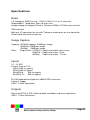
Mini MCA-6 Dimensions
Weight: 780 g
Multi-Camera Array User's Guide
Page 32
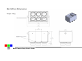
Mini MCA-12 Dimensions
Weight: 1300g
Multi-Camera Array User's Guide
Page 33
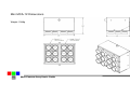
Std MCA-4 Dimensions
Weight: 1800g
Multi-Camera Array User's Guide
Page 34
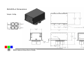
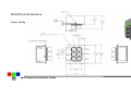
Std MCA-6 Dimensions
Weight: 2850g
Multi-Camera Array User's Guide
Page 35
Index
A
Accessory, 4
Adobe, 1
All, 1
analysis., 3
APIs, 27
applications., 20
C
cable, 4
calculation, 9
calibrate, 9
Calibration, 9
Camera, 1, 2, 4, 6, 12, 22, 28
CAMERASTATUS, 28
CAPTUREBUFFER, 28
CD, 2, 6, 20
CDROM, 4
CF, 3, 9, 20
CF card, 3, 9, 20
CLOSECAMERAPORT, 29
color, 6
compact flash, 9
compression, 10
configuration, 6
Contents, 1
Copyright, 1
cursor, 26
D
DCA, 26
DIB, 20, 27, 28, 29
display, 20
DLL, 20, 26, 27
Documentation, 1
DPCM, 29
E
ERASEIMAGES, 29
exposure, 28
Page 36
F
FASTSHOT, 29
file, 26, 27, 28, 29
firmware, 4
format, 20
G
GETCOMPRESSEDDATA, 29
GETIMAGE, 28
gray scale, 28
H
Hardware, 7
HOOKUP, 27
I
image,, 27
imageGreen, 26, 27, 29
imageNumber, 26, 27, 28, 29
IMAGESTATUS, 28
imported, 9
index, 9
Index, 36
Information, 4
install, 3
installation, 2, 4, 6, 20, 26
Installation, 7
interface, 2, 3, 20, 26, 27
J
JPEG, 29
L
LCD, 3, 10
LED, 10
library, 26
linking, 26
Multi-Camera Array User's Guide
M
manual, 2, 3, 6, 27
menu, 3, 12
monitor, 6
MULTISELECT, 28
Multi-sync, 6
N
States, 1
Status, 10
statusString, 26, 27, 28, 29
storage, 10
string, 26, 27, 28
structure, 26
SVGA, 6
SXGAADC, 26, 27
System, 6, 12
T
NIR, 9
Notices, 1
P
permission, 1
PixelWrench, 3, 6, 20
PixelWrench,, 3
PixRequest, 26, 27, 28, 29
Power, 4
previews, 3
processing, 27
ProgrammerPlug., 26
Table, 1
tag, 9
technical support, 2
Teflon, 9
translation, 27
TWAIN, 26
U
Unpacking, 4
USB, 2, 3, 4, 6, 12
User, 2
R
requestType, 26, 27, 28
Requirements, 6
resolution, 6
review, 3
S
SDRAM, 6
SETEXPOSURE, 28
SNAPSHOT, 29
Software, 6, 20
Specifications, 1
STAMP, 28
V
value, 28
VB, 27
vegetation, 9
version, 2, 6, 27
Version, 1
viewfinder, 10
W
Warranty, 4
Windows, 1, 2
Multi-Camera Array User's Guide
Page 37