1
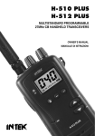
CM70
Contents
Specifications ................................................................................................................3
Control and Operation .................................................................................................4-7
Microphone ...................................................................................................................8
Installation ....................................................................................................................9
Installation of Main Unit ..................................................................................................9
Antenna Installation .......................................................................................................9
Operational test .............................................................................................................9
Frequency Bands Table ................................................................................................10
Frequency Band Selection .............................................................................................10
Table of Restrictions .....................................................................................................61
Updated Information on National Restrictions .................................................................62
Diagrams ............................................................................................................... 63-67
Declaration of Conformity .............................................................................................68
Language Pages
Page
Page
Page
Page
Page
Page
2-10
11-20
21-30
31-40
41-50
51-60
Page 2 of 68
English
Español
Français
Deutsch
Italiano
Polski
English
User Manual
English
User Manual
CM70
Specifications
General
Channels………………………………………..………...……………………………......…. 40 Ch AM/FM 4W
Frequency Range….………………………………….………….…...…………..….26.565 to 27.99125 MHz
Frequency Control……………………………………………….……………………………..…………………PLL
Operating Temperature Range……………………………………………..………………….….-10q / +55qC
DC Input Voltage……………………...…………………………………...………..............…13.2 V DC r15%
Size…………………………………….………………………………………..….182(L) X 37(H) X 139(D) mm
Weight…………………………………………………………………………………...……………………0.850 kg
Receiver
Receiving System…………………………………………………….….Dual Conversion Super Heterodyne
Intermediate Frequency……………………………….…….……….1st IF: 10.695 MHz, 2nd IF: 455 MHZ
Sensitivity………………………………………………..……………….0.5 PV for 20 db SINAD in FM mode
Audio Distortion………………………………………………………………………….Less than 8% @ 1 KHz
Image Rejection………………………………………………………………………………………………...65dB
Adjacent Channel Rejection………………………………………………………………………………….65dB
Signal/ Noise Ratio……………………………………………………………………………………………..45dB
Current Drain at standby……………………………………..……………….……………………….....250 mA
Current Drain at maximum audio…………………………….…………………………………………650 mA
Transmitter
Output Power…………………………………………………………………………..……...….4W @ 13.2 V DC
Modulation…………………………………………………..……………………...………FM: 1.8 KHz r0.2 KHz
Output impedance……………………………………………………...…………………RF 50 ohm Unbalance
Signal/ Noise Ratio……………………………………………………………….……………………..40 dB MIN
Current Drain……………………………………………………………………………….……………….1200 mA
Page 3 of 68
Specification
Frequency response……………………..……………..…….………………..……...From 400 Hz to 2.5 KHz
English
User Manual
CM70
Control and Operation
Front Panel
1. Power On/Off
This Button switches the radio ON and OFF.
2. LCD Display
This large, red backlit system allows clear readability. The LCD display shows all enabled functions as well as
several other features (programmable by the user), such as the channel readout or the full 5-digit frequency
readout. It also includes a digital 10-bar S/RF Meter to monitor the strength/power of received and
transmitted signals.
B. ESP C E Icon
The ESP icon is visible when the ESP (Electronic Speech Processor) function is enabled.
Page 4 of 68
Control and Operation
A. VOL Icon
The VOL icon is visible when adjustments are made to the volume control.
English
User Manual
CM70
C. LOCK Icon
The LOCK icon is visible when the LOCK function has been enabled.
D. AM Icon
The AM icon is visible when the radio receives and transmits in AM mode (amplitude modulation).
E. FM Icon
The FM icon is visible when radio receives and transmits in FM mode (frequency modulation).
F. DW Icon
The DW icon is visible when the DUAL WATCH function (automatic monitoring of two channels) is enabled.
The DW (Dual Watch) function allows automatic alternate monitoring of two programmable channels. Select
the first channel to be monitored using thejand i or the channel selection keys on the microphone. To
enable the DW function, press/hold the EMG key until the DW icon appears and blinks on the LCD display.
Now select the second channel to monitor using the j and i or the channel selection keys on the
microphone. Press/hold the EMG key. The DW function is now enabled and the LCD display will alternately
show the channel number of the two programmed channels. The DW icon will be visible on the LCD display.
Monitoring stops if a signal is detected on one of the two channels, in order to let the user listen to the
incoming signal and will start again when no signal is detected on that channel. It is possible to transmit on
that channel by simply pressing the PTT key. If there is no transmission within 5 seconds, monitoring will restart. To exit the DW mode, short press the PTT button.
G. H. I. Alphanumeric Digit
G. These two alphanumeric digits indicate the country code, in accordance with the programmed frequency
band (i.e. DE, UK, CE, etc.).
H. I. These three alphanumeric digits indicate the operating channel number (01 to 80, according to the
programmed frequency band), when the channel number readout function is enabled
J. ASQ Icon
The ASQ icon is visible when Auto Squelch enabled.
K. LO Icon
The LO icon is visible when the transmitter is in LOW POWER (1W) mode.
L. TX Icon
The TX icon is visible when radio is in transmit mode.
M. RX Icon
The RX icon is visible when radio is in receive mode.
O. VOLUME / SQUELCH Digital Level Icon
A digital 10-bar indicator displays the level of the volume and squelch.
P. S/RF Digital meter
A digital 10-bar S/RF METER indicates the strength of the received signal (from S0 to S9+30) in receive
mode and transmitter RF output power (0 to 4W) in transmit mode.
Q. EMG Icon
The EMG icon is visible when one of the pre-programmed emergency channels has been selected.
R. SCAN Icon
The SCAN icon is visible when the SCAN function (automatic search of busy channels) is enabled.
3. EMG (Emergency Channels) Key
This key allows quick access to one of the two pre-programmed emergency channels (CH9 or CH19). Each
time this key is pressed, radio will select CH9, then CH19, then again the normal operating channel. When
Page 5 of 68
Control and Operation
N. SQ Icon
The SQ icon is visible when adjusting the squelch control.
English
User Manual
CM70
one of the emergency channels is selected, the EMG icon will appear on the LCD display. The operating
mode (AM or FM) for the emergency channels are factory pre-programmed as per the following table.
COUNTRY CODE
I0
I2
DE
D2
EU
CE
SP
FR
UK
PL
CH-9
AM
AM
AM
AM
AM
FM
AM
AM
FM
AM
CH-19
AM
AM
AM
AM
AM
FM
AM
AM
FM
AM
4. AM/FM Key
This key allows the user to select the AM or FM operating mode in both RX and TX. The AM/FM operating
mode selection is possible only if it is allowed in the programmed frequency band.
5. SCAN Key
By pressing the SCAN key, the SCAN (automatic scanning of busy channels) function is enabled. To enable
the SCAN function, first adjust the SQUELCH level, until the background noise is cut out. Then press the
SCAN key, radio will automatically start scanning all channels continuously and the SCAN icon will appear on
the LCD. Auto-scan stops if a signal is detected on a channel, (in order for the user to hear the incoming
signal) and will start again when no signal is detected on that channel. If the PTT Key is pressed within 5
seconds, the radio will remain on that channel, otherwise scanning will start again. Auto-scan may be also
re-started at any time by pressing the SCAN key. To exit SCAN mode, short press the PTT button.
6. MICROPHONE Connector
Connect the supplied dynamic microphone via this connector, locking it via the ring nut.
7. MODE Key
Use the MODE key to enable and program the various function of the radio. Pressing the MODE key will
scroll through the various functions. The sequence of the various functions may vary depending on current
functions.
- ASQ Auto squelch control
or
appears on
To enable Auto Squelch control, press the MODE key repeatedly, until the icon
the LCD. Use the jor i to set the desired level and short press the PTT key to confirm and store your
selection.
- SQUELCH LEVEL
When you want to adjust the Squelch level, press the MODE key repeatedly, until the icon
the LCD. Use the
and
appears on
to increase or decrease the Squelch level.
- BEEP TONE
When a key is pressed, a beep tone is heard to confirm your command. You may enable or disable this beep
- LCD DISPLAY BACKLIGHT SETING
Press the MODE key repeatedly, until the icon
or
appears on the LCD. Use the j or i to set
the desired level and short press the PTT key to confirm and store your selection.
MEMORY CHANNELS (M0-M9) PROGRAMMING
Use the j or i key to select the channel to be stored as a memory channel. Pressing the MODE key several
(M0-M9) appears on the LCD display. Using the jor i to select a channel
times, until the icon
number to be stored in the memory, press/hold the MODE key, until the previously selected channel number
appears on the LCD. All data of that channel will be stored (Channel number, frequency readout, AM/FM
mode, transmitter power, etc.).
MEMORY CHANNELS RECALL
Press/hold the MODE key, the memory channel number (M0-M9) will appear on the LCD. Using the j or i
to select the desired memory channel. Press the MODE key again to exit memory channels recall mode.
Page 6 of 68
Control and Operation
or
appears on the LCD. Use the jor
tone, by pressing the MODE key repeatedly, until the icon
i to set the desired level and short press the PTT key to confirm and store your selection.
English
User Manual
CM70
8. UP – Down SLIDE BAR
Use the
and
to increase or decrease Volume and Squelch level.
9. ESP (Electronic Speech Processor) Key
The ESP (Electronic Speech Processor) is an exclusive advanced feature of the Maxon CM70 CB radio. ESP
(Electronic Speech Processor), works as a modulation compressor during transmission and as a modulation
expander during receive mode. The ESP obtains stronger, cleaner and clearer audio signals, great help in
noisy areas especially in the case of long distance communication or weak signals. The efficiency of ESP is
even greater when communicating with other radios using the same system. To enable or disable
the ESP function, press the ESP key. When enabled, the ESP icon appears on the LCD display.
ESP performance
of the modulation
in RX and TX modes
10. j (Quick Down) Key
This key allows fast selection of the operating channel downward. Each time this key is pressed, the channel
number moves down by 1 channel. Press this key for about 2 seconds, the channel number moves down by
10 channels.
11. i (Quick UP) Key
This key allows fast selection of the operating channel in increments. Each time this key is pressed, the
channel number moves up by 1 channel. Press/hold this key to move the channel number in groups of 10.
Rear Panel
13. S-METER Jack
This jack is for connecting an external S-METER (optional).
14. ANTENNA Connector
Antenna connector. Refer to the section INSTALLATION OF THE ANTENNA.
15. 13.8DC POWER CORD
13.8 DC power cord input.
Page 7 of 68
Control and Operation
12. EXT (External Speaker) Jack
This jack is for connecting an external speaker (optional).
English
User Manual
CM70
MICROPHONE
16
17
18
19
20
16. PTT (Push-to-Talk) Key
Transmitter key. Press the PTT key to transmit and release it to return to the receive mode.
17. UP (Channel Selector) Key
Each time this key is pressed, the channel number will move upward by one channel.
* Can be used instead of i
You can use this key to set ASQ, SQ, BEEP TONE, BACKLIGHT and MEMORY. This key is the same as the
MODE Key on the front of the radio.
* You can also use this key for increasing or decreasing volume level.
or
appears on the LCD. The UP
Pressing the LOCK/MODE key several times, until the icon
KEY or DN Key on microphone can also be used to increase or decrease the volume level.
19. DOWN (Channel Selector) Key
Each time this key is pressed, the channel number will move downward by one channel.
* Can be used instead of j
20. MICROPHONE Plug
The 6-pin microphone plug with locking ring nut is connected to the microphone connector located on the
front of the radio.
Page 8 of 68
Control and Operation
18. LOCK/MODE Key
The LOCK function is enabled by a press/hold of this key locks the keypad and prevents the activation of
unwanted features. When the LOCK function is enabled, the LOCK icon appears on the LCD display.
English
User Manual
CM70
Installation
Before installing the main unit in a vehicle, check and select the most convenient location, so the radio will
be easy to reach and comfortable to operate, without disturbing or interfering with operating the vehicle.
Use the supplied bracket and hardware to install the radio. The bracket screws must be well tightened in
order not to become loose with vehicle vibrations. The car mounting bracket can be installed above or below
the radio and the radio may be tilted as desired according to the specific type of installation (under
dashboard or track cabin roof installation).
Installation of Main Unit
Before connecting the radio to the vehicles electrical system, ensure that radio is switched off. The DC
power cable is complete with a fuse holder (fuse located on the red positive (+) wire). Connect the DC
power cable to the vehicles electrical system, pay special attention to correct polarity, even if the radio is
protected against polarity inversion. Connect the red wire to the positive (+) pole and the black wire to the
negative (-) pole of the vehicles electrical system. Ensure that wires and terminals are firmly connected, in
order to prevent cables from disconnecting or causing short circuits.
Installation of the Antenna
A specific mobile antenna adjusted for 27 MHz frequency range must be used. The antenna installation must
be carried out by a specialist technician or service centre. Please take special care to fully install the antenna
on the vehicle with a perfect connection to ground. Before connecting the antenna to the radio, it is
necessary to check the correct operation of the antenna with low standing wave ratio (S.W.R.), using
adequate instruments. If not, the transmitter circuit of the radio could be damaged. The antenna is usually
installed on the highest part of the vehicle, free from obstacles and as far away as possible from any source
of electric or electromagnetic noise. The RF antenna coaxial cable must not be damaged or pressed on its
way between antenna and the radio. The correct operation of the antenna and the low standing wave ratio
(S.W.R.) must be checked periodically. Connect the RF antenna coaxial cable to the antenna Connector,
located on the rear side of the radio.
Operational Test
Once the radio has been connected to the vehicles power supply and the antenna is installed, the operation
of the system can be check and tested. Please proceed as follows:
1.)
2.)
3.)
4.)
5.)
6.)
7.)
8.)
Make sue the unit is installed correctly.
Check that the power cable is fitted correctly.
Check that RF antenna coaxial connector is correctly fitted.
Fit the microphone to the front panel connector.
Power on the unit and select correct Frequency band for country of use. (see page 10)
Adjust the squelch to be open (noise from speaker) via mode key, select SQ and use j or i.
Select desired channel using j or i.
Press PTT (Push To Talk) to transmit and release to receive.
If the test is successful the unit is ready to use. If you incur any problems please contact your dealer.
Installation
Page 9 of 68
English
User Manual
CM70
Frequency Bands Table
The CM70 transceiver includes an advanced multi-standard programmable circuit, which allows the user to
program different frequency bands, specifications and operating modes (in conformity with the regulations
in the country where the product is being used). 10 programmable frequency bands are available, as per the
below table:
COUNTRY
CODE
COUNTRY
I0
ITALY
I2
ITALY
DE
GERMANY
D2
GERMANY
40CH FM 4W - 12CH AM 1W
EU
EUROPE
40CH FM 4W - 40CH AM 1W
CE
CEPT
SP
SPAIN
FR
FRANCE
UK
UK
PL
POLAND
SPECIFICATIONS (CH, operating
modes, TX power)
40CH AM / FM 4W
36CH AM / FM 4W
80CH FM 4W - 12CH AM 1W
40CH FM 4W
40CH AM
/
FM 4W
40CH FM 4W - 40CH AM 1W
40CH FM 4W UK FREQUENCIES -40CH FM 4W
CEPT FREQUENCIES
40CH AM
/
FM 4W POLISH FREQUENCIES
Attention! This radio has been factory pre-programmed on the CE frequency band (CEPT 40CH FM 4W),
since this standard is currently accepted in all the European countries. Please refer to the information table
(Restrictions on the use of CB transceivers).
Frequency Band Selection /Programming
The radio must be programmed and used exclusively on a frequency band allowed in the country where the
product is used. It is possible to program a different frequency band, as per the following procedures:
1) Switch off the radio.
2) Press and hold the EMG key while turning on the radio, using the Power knob – Release while
all displayed icons are still lit.
3) The current country code will blink on the LCD display (2 digits).
4) Now select the desired new country code, using the jor i.
5) Shortly press the EMG key to confirm.
Frequency band Table
Page 10 of 68