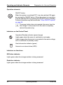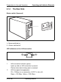
1
PRIMERGY
PRIMERGY Econel 100
Server System
Operating Manual
Jesús López
cognitas. Gesellschaft für Technik-Dokumentation mbH cognitas PC
Alte Landstraße 6
D
81730 Munich
e-mail: e-mail:[email protected]
Tel.: (089) 61001-137
Fax: (++49) 700 / 372 00000
Econel 100
Sprachen: De
Edition November 2005
Comments… Suggestions… Corrections…
The User Documentation Department would like to
know your opinion of this manual. Your feedback helps
us optimize our documentation to suit your individual
needs.
Fax forms for sending us your comments are included in
the back of the manual.
There you will also find the addresses of the relevant
User Documentation Department.
Certified documentation
according to DIN EN ISO 9001:2000
To ensure a consistently high quality standard and
user-friendliness, this documentation was created to
meet the regulations of a quality management system
which complies with the requirements of the standard
DIN EN ISO 9001:2000.
cognitas. Gesellschaft für Technik-Dokumentation mbH
www.cognitas.de
Copyright and Trademarks
Copyright © 2005 Fujitsu Siemens Computers GmbH.
All rights reserved.
Delivery subject to availability; right of technical modifications reserved.
All hardware and software names used are trademarks of their respective manufacturers.
Content
1
1.1
1.2
1.3
1.4
Introduction . . . . . . . . .
Overview of the Documentation
Features . . . . . . . . . . . .
Notational conventions . . . .
Technical data . . . . . . . . .
.
.
.
.
.
2
Installation Steps: Overview
. . . . . . . . . . . . . . . . .
3
3.1
3.2
3.3
3.4
3.5
Important Notes . . . . . . . . . .
Safety . . . . . . . . . . . . . . . .
CE Certificate . . . . . . . . . . . .
FCC Class A Compliance Statement
Transporting the Server . . . . . . .
Environment Protection . . . . . . .
.
.
.
.
.
.
.
.
.
.
.
.
.
.
.
.
.
.
.
.
.
.
.
.
.
.
.
.
.
.
.
.
.
.
.
.
.
.
.
.
.
.
.
.
.
.
.
.
.
.
.
.
.
.
.
.
.
.
.
.
.
.
.
.
.
.
15
15
21
22
23
23
4
4.1
4.2
4.3
4.4
4.5
4.6
Hardware Installation . . . . . . . . . . .
Installation Steps . . . . . . . . . . . . . .
Unpacking the Server . . . . . . . . . . . .
Setting up the Server . . . . . . . . . . . .
Connecting Devices to the Rack Model . . .
Connecting the Server to the Line Voltage .
Instructions: Connecting/disconnecting wires
.
.
.
.
.
.
.
.
.
.
.
.
.
.
.
.
.
.
.
.
.
.
.
.
.
.
.
.
.
.
.
.
.
.
.
.
.
.
.
.
.
.
.
.
.
.
.
.
.
.
.
.
.
.
.
.
.
.
.
.
.
.
.
.
.
.
.
.
.
.
25
26
26
27
28
29
30
5
5.1
5.1.1
5.1.2
5.2
5.3
5.3.1
5.3.2
5.3.3
5.4
Preparation for Use and Operation .
Operating and Indicator Elements . . .
The Front Side . . . . . . . . . . . . .
The Rear Side . . . . . . . . . . . . .
Switching the Server ON and OFF . .
Configuring the Server . . . . . . . .
Configuring the SATA RAID Controller
Configuration with ServerStart . . . .
Configuration without ServerStart . . .
Cleaning the Server . . . . . . . . . .
.
.
.
.
.
.
.
.
.
.
.
.
.
.
.
.
.
.
.
.
.
.
.
.
.
.
.
.
.
.
.
.
.
.
.
.
.
.
.
.
.
.
.
.
.
.
.
.
.
.
.
.
.
.
.
.
.
.
.
.
.
.
.
.
.
.
.
.
.
.
.
.
.
.
.
.
.
.
.
.
.
.
.
.
.
.
.
.
.
.
.
.
.
.
.
.
.
.
.
.
31
31
31
33
34
36
36
36
37
37
6
6.1
6.2
Property and Data Protection . . . . . . . . . . . . . . . . .
Mechanical access protection . . . . . . . . . . . . . . . . . .
BIOS Setup Security Functions . . . . . . . . . . . . . . . . .
39
39
40
Econel 100
.
.
.
.
.
.
.
.
.
.
Operating Manual
.
.
.
.
.
.
.
.
.
.
.
.
.
.
.
.
.
.
.
.
.
.
.
.
.
.
.
.
.
.
.
.
.
.
.
.
.
.
.
.
.
.
.
.
.
.
.
.
.
.
.
.
.
.
.
.
.
.
.
.
.
.
.
.
.
.
.
.
.
.
.
.
.
.
.
.
.
.
.
.
.
.
.
.
.
.
.
.
.
.
.
.
.
.
.
.
.
.
.
.
.
.
.
.
.
.
.
.
.
.
.
.
.
.
.
.
.
.
.
.
.
.
5
5
7
9
10
13
Content
7
7.1
7.2
7.3
7.4
7.5
7.6
7.7
7.8
7.9
7.10
Troubleshooting and Tips . . . . . . . . .
Power-On Indicator Remains Dark . . . . .
Screen Remains Blank . . . . . . . . . . .
Flickering Stripes on the Monitor Screen . .
No Screen Display or the Display Drifts . . .
No Mouse Pointer Displayed on Screen . . .
Floppy Disk Cannot be Read and/or Written
Incorrect Time and/or Date . . . . . . . . .
Drives Are Reported as “Dead” . . . . . . .
Added Drive Reported Defective . . . . . .
Error Messages on the Screen . . . . . . .
.
.
.
.
.
.
.
.
.
.
.
41
41
42
43
43
44
44
45
45
45
45
Abbreviations . . . . . . . . . . . . . . . . . . . . . . . . . . . . . . .
47
Bibliography
. . . . . . . . . . . . . . . . . . . . . . . . . . . . . . .
55
Index . . . . . . . . . . . . . . . . . . . . . . . . . . . . . . . . . . . .
57
Operating Manual
.
.
.
.
.
.
.
.
.
.
.
.
.
.
.
.
.
.
.
.
.
.
.
.
.
.
.
.
.
.
.
.
.
.
.
.
.
.
.
.
.
.
.
.
.
.
.
.
.
.
.
.
.
.
.
.
.
.
.
.
.
.
.
.
.
.
.
.
.
.
.
.
.
.
.
.
.
.
.
.
.
.
.
.
.
.
.
.
.
.
.
.
.
.
.
.
.
.
.
Econel 100
1
Introduction
The PRIMERGY Econel 100 server is an Intel-based server for workgroups and
small networks. The server is suitable for use as a file server and also as an
application, information or Internet server.
The PRIMERGY Econel 100 server offers a high level of reliability and availability through highly developed hardware and software components.
Security functions in the BIOS Setup and on the system board protect the data
on the server against manipulation. The supported RAID levels allow the hard
disk controllers to offer error tolerance, through data redundancy, for users who
want to provide complete protection for valuable data.
1.1
Overview of the Documentation
I PRIMERGY manuals are available in PDF format on the ServerBooks CD.
The ServerBooks CD is part of the ServerStart Suite delivered with each
server system.
The PDF files for the manuals can also be downloaded free of charge
from the Internet. The overview page showing the online documentation
available in the Internet can be found via the URL: http://manuals.fujitsusiemens.com. The PRIMERGY server documentation can be accessed via
the industry standard servers navigation point.
Concept and target group of this manual
This operating manual describes how to install, how to set up and how to
operate your server.
This manual is intended for those responsible for installing the hardware and
ensuring that the system runs smoothly. The manual contains all the information
required for installing and operating your PRIMERGY Econel 100.
To understand the manual, you will need knowledge of hardware and data transmission, as well as basic knowledge of the operating system used. You should
also have a good working knowledge of the English language.
Econel 100
Operating Manual
5
Overview of the Documentation
Introduction
Additional server documentation
To the PRIMERGY Econel 100 documentation set belong the following
additional manuals:
– “Quick Start Hardware - PRIMERGY Econel 100” (poster)
– “Quick Start Software - PRIMERGY ServerView Suite” (poster)
– “Warranty” manual (print version delivered together with the system, PDF file
available on the ServerBooks CD)
– “Warranty” manual (print version delivered together with the system, PDF file
available on the ServerBooks CD)
– “Ergonomics” manual (PDF file available on the ServerBooks CD)
– “Returning used devices” manual (PDF file available on the ServerBooks CD)
– “Help Desk” (supplement with worldwide help desk telephone numbers)
– Technical Manual for the system board D2179 (PDF file available on the
ServerBooks CD)
– “BIOS Setup” manual (PDF file available on the ServerBooks CD)
– “PRIMERGY Econel 100 Server System Options Guide” (PDF file available
on the ServerBooks CD)
I In the “Options Guide”, the server extension and modification possibilities are described.
– The “ServerView Suite” contains the ServerStart CD, the ServerBooks CD and
the ServerSupport CDs. The PDF version of the “PRIMERGY ServerView
Suite - ServerStart” user manual is also available on the ServerBooks CD.
– “LSI SATA Software RAID User’s Guide” (PDF file available on
theServerBooks CD)
I If you need a backup of the ServerBooksCD send the details of your server
via email address:
[email protected]
Further sources of information:
–
–
–
–
–
manual for the monitor
manual for ServerView server management
documentation for the boards and drives
operating system documentation
information files of your operating system
(see also “Bibliography” on page 55).
6
Operating Manual
Econel 100
Introduction
1.2
Features
Features
System board
The features of the system board can be found in the technical manual of the
system board D2179 for the hardware and in the BIOS Setup for the firmware
(see “Bibliography” on page 55).
Hard disk drives
Up to four SATA hard disk drives, each with a maximum height of 1 inch, are built
into the drive rack. There is a wire connection to the controller.
Onboard SATA RAID controller
A SATA RAID controller is integrated on the system board; up to four SATA hard
disk drives can be connected to the controller. RAID levels 0, 1 and 10 are
supported for each LSI SATA software RAID.
I The controller has its own configuration utility. More detailed information
may be found in the “LSI SATA Software RAID User’s Guide” manual (on
the ServerBooks CD under “Controller”).
Accessible drives
The first (top) bay contains the server's DVD drive. The fourth (bottom) bay can
be used for a 3.5" disk drive (1.44 Mbyte).
The two middle 5.25" bays are available for additional usable drives (CD/DVD
drives or a magnetic tape drive).
The accessible drives cannot be replaced during operation.
Power supply
The server has a built-in power supply unit, which automatically sets itself to a
mains voltage in the range of 100 V - 240 V.
High level of availability and reliability
When memory data is accessed, 1-bit errors in the main memory are recognized and automatically corrected with the ECC (Error Correcting Code)
method.
Econel 100
Operating Manual
7
Features
Introduction
Server management
Server management is implemented with the aid of the supplied ServerView
software and PDA (Prefailure Detection and Analyzing) technology from Fujitsu
Siemens. PDA reports the threat of a system error or overloading early on so
that preventative measures can be taken.
ServerView enables the management of all PRIMERGY servers in the network
via a central console. Here ServerView supports the following functions:
●
Remote power-on (Wake On LAN)
●
Intrusion detection
●
Temperature monitoring of the CPU and the surrounding area
●
Power monitoring
●
Fan monitoring
●
Watchdog timer for monitoring the operating system and applications
Further information on ServerView server management is provided in the
associated documentation (see “Bibliography” on page 55).
ServerStart
You can configure the PRIMERGY server quickly and purposefully with the
ServerStart software provided. User-guided menus are available for installing the
server operating system.
Service and Support
PRIMERGY servers are service-friendly and modular, thus enabling quick and
simple maintenance. The flash EPROM program supplied with the Fujitsu
Siemens Computers utilities supports a fast BIOS update.
8
Operating Manual
Econel 100
Introduction
1.3
Notational conventions
Notational conventions
The following notational conventions are used in this manual:
text in italics
indicate commands, menu items or software programs.
“Quotation marks”
indicate names of chapters and terms that are being
emphasized.
Ê
describes activities that must be performed in the order
shown
V CAUTION!
I
Pay particular attention to texts marked with this
symbol. Failure to observe this warning may endanger
your life, destroy the system or lead to the loss of data.
indicates additional information, notes and tips
Table 1: notational conventions
Econel 100
Operating Manual
9
Technical data
1.4
Introduction
Technical data
Electrical data (standard and redundant power supply)
Rated voltage range
100 V - 240 V
Frequency
50 Hz - 60 Hz
Rated current in basic configuration
100 V - 240 V / 1.5 A - 0.6 A
Max. rated current:
100 V - 240 V / 7.5 A - 3.5 A
Effective power
216 W
Apparent power
227 VA
Heat dissipation
778 kJ/h (737 btu/h)
Main power fuse
16 A
Protection class
I
National and international standards
Product safety and ergonomics
IEC 60950 / EN 60950 / UL 60950,
CSA 22,2 No. 60950
Electromagnetic Compatibility
FCC class A
VCCI class A
AS/NZS 3548 class A
CNS 13438
Interference emission
EN 55022
Harmonic current
EN 6100-3-2 JEIDA
flicker
EN 61000-3-3
Interference immunity
EN 55024
CE label according to EU directives Low-Voltage Directive 73/23/EEC
Electromagnetic Compatibility
89/336/EEC (Product safety)
10
Operating Manual
Econel 100
Introduction
Technical data
Mechanical values
Width
205 mm
Total depth
505 mm
Height
385 mm (including feets)
Weight
Approx. 15 - 19 kg (depending on configuration)
Ventilation clearance
At least 200 mm at the front and rear, 200 mm to the left and right
Environmental conditions
Environment class 3K2
Environment class 2K2
EN 60721 Part 3-3
EN 60721 Part 3-2
Temperature:
●
Operating (3K2)
15 °C ... 35 °C
●
Transport (2K2)
-25 °C ... 60 °C
Humidity
10% ... 85%
Condensation during operation must be avoided!
Noise level
Sound power level LWAd (ISO 9296)
≤ 4.3 B (standby)
≤ 4.5 B (operation)
Sound pressure level at bystander position
LpAm (ISO 9296)
≤ 24 dB (A) (standby)
≤ 27 dB (A) (operation)
Econel 100
Operating Manual
11
2
Installation Steps: Overview
In this chapter you will find an overview of the steps necessary to install your
server system. Links guide you to sections where you can find more detailed
information on the individual steps:
Ê At first, please take notice of chapter “Important Notes” on page 15 and
following.
Ê Transport the server to the place where you want to set it up.
Ê Unpack the system, check the contents of the package for visible transport
damage and check whether the delivery agrees with the details in the
delivery note (see section “Unpacking the Server” on page 26).
Ê Make sure all necessary manuals (see “Additional server documentation” on
page 6) are available; possibly print of the PDF files.
Ê Set up the server (see section “Setting up the Server” on page 27).
Ê Cable the server. Please take note of the section “Connecting Devices to the
Rack Model” on page 28 and the section “Instructions: Connecting/disconnecting wires” on page 30.
Ê Connect the system to the line voltage (see section “Connecting the Server
to the Line Voltage” on page 29).
Ê Make yourself familiar with the operating and indicator elements on the front
and on the rear side of the server (see section “Operating and Indicator
Elements” on page 31).
Econel 100
Operating Manual
13
Installation Steps: Overview
Ê Configure the server and install the desired operating system and applications. To do so, you have the following possibilities:
– Remote configuration and installation with ServerStart:
With the ServerStart-CD provided, you can configure the server and install
the operating system in a convenient manner.
Information on how to operate ServerStart, as well as further information,
may be found in the "ServerView Suite - ServerStart" manual, supplied
as a PDF file.
You find additional information for configuration in section “Configuration
with ServerStart” on page 36.
– Local configuration and installation with and/or without ServerStart (see
section “Configuration with ServerStart” on page 36 and/or section
“Configuration without ServerStart” on page 37).
14
Operating Manual
Econel 100
3
Important Notes
In this chapter you will find essential information regarding safety when working
with your server.
3.1
Safety
I The following safety information may also be found in the “Safety”
manual.
This device meets the relevant safety regulations for IT equipment.
If you have any questions about where you can set up the device, contact your
sales outlet or our customer service team.
V CAUTION!
The activities described in these instructions may only be performed by
engineers or maintenance/technical staff. Device repairs may only be
carried out by authorized qualified personnel. Any unauthorized
openings and improper repairs could expose the user to risks (electric
shock, energy hazards, fire hazards) and could also damage the
equipment. Please note that any unauthorized openings of the device will
result in the invalidation of the warranty and exclusion from all liability.
Econel 100
Operating Manual
15
Safety
Important Notes
Before operating the device
V CAUTION!
●
During installation and before operating the device, observe the
instructions on environmental conditions for your device (see section
“Technical data” on page 10).
●
If the device is brought in from a cold environment, condensation may
form both inside and on the outside of the machine.
Wait until the device has acclimatized to room temperature and is
absolutely dry before starting it up. Material damage may be caused
to the device if this requirement is not observed.
●
Transport the device only in the original packaging or in packaging
that protects it from knocks and jolts.
Installation and operation
V CAUTION!
16
●
If the rack model is integrated in an installation that receives power
from an industrial (public) power supply network with the IEC309
connector, the (public) power supply protection must comply with the
requirements for non-industrial (public) power supply networks for the
type A connector.
●
The server is automatically set to a mains voltage in the range of
100 V - 240 V. Make sure that your local voltage is within this range.
●
This device has a specially approved power cable and must only be
connected to a grounded insulated socket.
●
Ensure that the power socket on the device or the grounded wall
outlet is freely accessible.
●
The power switch does not disconnect the device from the mains
voltage. To completely disconnect it from the mains voltage, remove
the power plug from the power socket.
Operating Manual
Econel 100
Important Notes
Safety
V CAUTION!
●
Always connect the device and the attached peripherals to the same
power circuit. Otherwise you run the risk of losing data if, for example,
the central processing unit is still running but the peripheral device
(e.g. storage subsystem) has failed during a power outage.
●
Data cables must be adequately shielded.
●
The EN 50173 and EN 50174-1/2 standards apply for LAN cabling. A
minimum requirement is the use of a category 5 screened LAN line
for 10/100 Mbps Ethernet, or a category 5e line for Gigabit Ethernet.
The requirements of the specification ISO/IEC 11801 are to be
considered.
●
When setting up the server, make sure that the tilt guard provided is
mounted properly (tilting risk).
●
Route the cables in such a way that they do not form a potential
hazard (make sure no-one can trip over them) and that they cannot
be damaged. When connecting up a device, refer to the relevant
notes in this manual.
●
Never connect or disconnect data transmission lines during a storm
(lightning hazard).
●
Otherwise you run the risk of losing data if, for example, the central
processing unit is still running but the peripheral device (e.g. storage
subsystem) has failed during a power outage.
●
In emergencies (e.g. damaged casing, controls or cables, penetration
of liquids or foreign matter), switch off the device immediately, remove
the power plug and contact your sales outlet or customer service
team.
●
Proper operation of the system (in accordance with IEC
60950/EN 60950) is only ensured if the casing is completely
assembled and the rear covers for the installation openings have
been put in place (electric shock, cooling, fire protection, interference
suppression).
Econel 100
Operating Manual
17
Safety
Important Notes
V CAUTION!
●
Only install system expansions that satisfy the requirements and
rules governing safety and electromagnetic compatibility and relating
to telecommunications terminal equipment. If you install other expansions, you may damage the system or violate the safety regulations
and regulations governing RFI suppression. Information on which
system expansions are suitable can be obtained from the customer
service centre or your sales outlet.
●
The components marked with a warning label (e.g. lightning symbol)
may only be opened, removed or exchanged by authorized, qualified
personnel.
●
The warranty expires if the device is damaged during the installation
or replacement of system expansions.
●
You may only set those resolutions and refresh rates specified in the
"Technical data" section of the monitor description. Otherwise, you
may damage your monitor. If you are in any doubt, contact your sales
outlet or customer service centre.
Batteries
V CAUTION!
18
●
Incorrect replacement of batteries may lead to a risk of explosion. The
batteries may only be replaced with identical batteries or with a type
recommended by the manufacturer (see the technical manual for the
system board under “Bibliography” on page 55).
●
Replace the lithium battery on the system board in accordance with
the instructions in the technical manual for the system board (see
“Bibliography” on page 55).
Operating Manual
Econel 100
Important Notes
Safety
Working with CDs/DVDs and CD/DVD drives
V CAUTION!
●
Use only acceptable CDs/DVDs in your server's CD/DVD drive, in
order to avoid data loss, device damage and injury.
●
Therefore, check each CD/DVD for damage, cracks, breakage etc.
before inserting it in the drive.
Please note that any additional labels applied may change the
mechanical properties of a CD/DVD and cause imbalance.
Damaged and imbalanced CDs/DVDs can break at high drive speeds
(data loss).
In certain circumstances, sharp CD/DVD fragments can pierce the
cover of the CD/DVD drive (device damage) and can fly out of the
device (danger of injury, particularly to uncovered body parts such as
the face or neck).
I You can prevent mechanical damage and damage to the CD/DVD drive,
as well as premature CD/DVD wear, by observing the following advice:
– Only insert the CDs/DVDs in the drive when needed and remove
them after use.
– Store the CDs/DVDs in suitable sleeves.
– Protect the CDs/DVDs from exposure to heat and direct sunlight.
Note about the laser
The CD/DVD drive corresponds to the IEC 60825-1 laser class 1.
V CAUTION!
The CD/DVD drive contains a light-emitting diode (LED), which under
certain circumstances produces a laser beam stronger than laser
class 1. Direct view into the laser beam is dangerous.
Never remove parts of the CD/DVD drive casing!
Econel 100
Operating Manual
19
Safety
Important Notes
Modules with electrostatic-sensitive components:
Systems and components that might be damaged by electrostatic discharge
(ESD) are marked with the following label:
Figure 1: ESD label
When you handle components fitted with ESDs, you must observe the following
points under all circumstances:
●
You must always discharge yourself of static charges (e.g. by touching a
grounded object) before working.
●
Use a grounding cable designed for this purpose to connect yourself to the
system unit as you install components.
●
The equipment and tools you use must be free of static charges.
●
Remove the power plug from the power socket before inserting or removing
components containing ESDs.
●
Hold the components only at the edges or by the green Touch Points.
●
Do not touch any exposed pins or conductors on a component.
●
Place all components on a static-safe base.
I You will find a detailed description for handling ESD components in the
relevant European or international standards (EN 61340-5-1,
ANSI/ESD S20.20).
20
Operating Manual
Econel 100
Important Notes
CE Certificate
Other important points:
●
When cleaning the server, observe the relevant notes in the section
“Cleaning the Server” on page 37.
●
Keep these operating instructions and the further documentation (such as
the Technical Manual, CD) near the device. All documentation should be
included if the device is passed on to a third party.
3.2
CE Certificate
The shipped version of this device complies with the requirements
of the EEC directives 89/336/EEC “Electromagnetic compatibility”
and 73/23/EEC “Low voltage directive”. The device therefore
qualifies for the CE certificate (CE=Communauté Européenne).
Econel 100
Operating Manual
21
FCC Class A Compliance Statement
3.3
Important Notes
FCC Class A Compliance Statement
If there is an FCC statement on the device, then:
The following statement applies to the products covered in this manual, unless
otherwise specified herein. The statement for other products will appear in the
accompanying documentation.
NOTE:
This equipment has been tested and found to comply with the limits for a
“Class A” digital device, pursuant to Part 15 of the FCC rules and meets all
requirements of the Canadian Interference-Causing Equipment Standard
ICES-003 for digital apparatus. These limits are designed to provide reasonable
protection against harmful interference in a residential installation. This
equipment generates, uses and can radiate radio frequency energy and, if not
installed and used in strict accordance with the instructions, may cause harmful
interference to radio communications. However, there is no warranty that interference will not occur in a particular installation. If this equipment does cause
harmful interference to radio or television reception, which can be determined
by turning the equipment off and on, the user is encouraged to try to correct the
interference by one or more of the following measures:
●
Reorient or relocate the receiving antenna.
●
Increase the separation between equipment and the receiver.
●
Connect the equipment into an outlet on a circuit different from that to which
the receiver is connected.
●
Consult the dealer or an experienced radio/TV technician for help.
Fujitsu Siemens Computers is not responsible for any radio or television interference caused by unauthorized modifications of this equipment or the substitution or attachment of connecting cables and equipment other than those
specified by Fujitsu Siemens Computers. The correction of interferences
caused by such unauthorized modification, substitution or attachment will be the
responsibility of the user.
The use of shielded I/O cables is required when connecting this equipment to
any and all optional peripheral or host devices. Failure to do so may violate FCC
and ICES rules.
22
Operating Manual
Econel 100
Important Notes
3.4
Transporting the Server
Transporting the Server
V CAUTION!
Only transport the server to the new site in its original packaging or in
packaging that protects it from knocks and jolts. Do not unpack the server
until it is at its installation location.
If you need to lift or transport the server, ask other people to help you.
3.5
Environment Protection
Environmentally-friendly product design and development
This means that the designers have taken into account decisive criteria such as
durability, selection of materials and coding, emissions, packaging, the ease
with which the product can be dismantled, and the extent to which it can be
recycled. This means that key factors such as durability, selection and labeling
of materials, emissions, packaging, ease of disassembly and recycling have
been taken into account.
This saves resources and thus reduces the harm done to the environment.
Notes on saving energy.
Devices that do not have to be switched on permanently should be switched off
until they are needed as well as during long breaks and after completion of work.
Notes on packaging
Please do not throw away the packaging. You may need it later for transporting
your system unit. If possible, the device should only be transported in its original
packaging.
Econel 100
Operating Manual
23
Environment Protection
Important Notes
Notes on dealing with consumables
Please dispose of printer consumables and batteries in accordance with local
government regulations.
In accordance with EU directives, batteries must not be disposed of together
with unsorted domestic waste. They must be disposed of in accordance with
local regulations concerning special waste.
All batteries containing pollutants are marked with a symbol (a crossed-out
garbage can). In addition, the marking is provided with the chemical symbol of
the heavy metal decisive for the classification as a pollutant:
Cd Cadmium
Hg Mercury
Pb Lead
Note on labeling plastic parts
Please avoid sticking your own labels on plastic parts wherever possible, since
this makes it difficult to recycle them.
Returning, recycling and disposal
The device must not be disposed of together with domestic waste.
This device is labeled according to European directive 2002/96/EG
on waste electrical and electronic equipment (WEEE).
This directive sets the framework for withdrawing and recycling used
devices; this is valid across the EU. When returning your used
device, please use the return and collection systems available to
you. Further information may be found at www.fujitsusiemens.com/recycling.
Details regarding the return and recycling of devices and expendable items
within Europe may also be found in the "Returning used devices" manual, via
your local Fujitsu Siemens Computers branch or from our recycling center in
Paderborn:
Fujitsu Siemens Computers
Recycling Center
D-33106 Paderborn
Tel.
+49 5251 8 18010
Fax
+49 5251 8 18015
24
Operating Manual
Econel 100
4
Hardware Installation
V CAUTION!
Please note the safety instructions in chapter “Important Notes” on
page 15.
Do not expose the server to extreme environmental conditions (see
section “Technical data” on page 10). Protect it from dust, humidity, and
heat.
The server must be acclimatized in its operating environment for an acclimatization time.
Temperature difference (°C)
(operating environment/outside)
Minimum acclimatization time
(hours)
5
3
10
5
15
7
20
8
25
9
30
10
Table 2: acclimatization Time
Econel 100
Operating Manual
25
Installation Steps
4.1
Hardware Installation
Installation Steps
The following installation steps are described in detail in other sections of this
chapter:
●
Transporting the server to the desired assembly location.
●
Unpack the server (see the next section “Unpacking the Server”).
●
Setting up the server (see section “Setting up the Server” on page 27).
●
Cabling the server. Please take note of the section “Connecting Devices to
the Rack Model” on page 28 and the section “Instructions:
Connecting/disconnecting wires” on page 30.
●
Connect the server to the power supply (see section “Connecting the Server
to the Line Voltage” on page 29).
4.2
Unpacking the Server
V CAUTION!
Please observe the safety information in the chapter “Important Notes”
on page 15.
If you need to lift or transport the server, ask other people to help you.
Do not unpack the server until it is at its assembly location.
It is recommended not to throw away the original packaging material as it may
be required for transportation at a later date.
Ê Unpack all individual parts.
Ê Check the delivery for any damage during transport.
Ê Check whether the delivery agrees with the details on the delivery receipt.
The type rating is indicated on a label on the upper part of the server.
Notify your supplier immediately should you discover that the delivery does not
correspond to the delivery receipt.
26
Operating Manual
Econel 100
Hardware Installation
4.3
Setting up the Server
Setting up the Server
Ê Set up the Server.
V CAUTION!
– The device must be protected against direct sunlight.
– The required minimum distances for operation and maintenance
areas must be adhered to.
– In order to connect other devices (e. g.: starage subsystem) the
rear of the server must be accessible.
– The mains plug must be accessible easily and safely.
– There must be a clearance of at least 200 mm in front of and
behind the server to ensure adequate ventilation.
Ê Cable the server. Please take note of the section “Connecting Devices to the
Rack Model” on page 28 and the section “Instructions: Connecting/disconnecting wires” on page 30.
Ê Connect the system to the line voltage (see section “Connecting the Server
to the Line Voltage” on page 29).
Econel 100
Operating Manual
27
Connecting Devices to the Rack Model
4.4
Hardware Installation
Connecting Devices to the Rack Model
The ports for external devices are on the front and on the rear of the server.
Which additional ports are available on your server depends on the PCI boards
installed. For further information please consult the "Options Guide" (see “Bibliography” on page 55).
The standard ports (figure 2) are marked with symbols, and some are colourcoded.
1
8
2
7
6
3
5
4
Figure 2: connections
1 Mouse port (PS/2) (green)
5
Monitor port (VGA) (blue)
2 Parallel port (burgundy)
6
Serial port COM1 (turquoise)
3 LAN connection (RJ45)
7
USB1 port 1 and 2 (black)
4 USB0 port 1 and 2 (black)
8
Keyboard port (PS/2) (purple)
I Some of the devices that can be connected may require special drivers
(see the documentation for the connected device).
Ê Connect the data cables to the server and peripherals.
Two further USB ports are located on the front of the server (see figure 4 on
page 31).
28
Operating Manual
Econel 100
Hardware Installation
4.5
Connecting the Server to the Line Voltage
Connecting the Server to the Line Voltage
The server is fitted with a built-in power supply.
V CAUTION!
The server is automatically set to a mains voltage in the range of 100 V
- 240 V. The server may be place in operation only, if the mains voltage
range set on the server corresponds to the local mains voltage.
1
2
Figure 3: connecting the Server to the Line Voltage
Ê Connect the power cord to the server's power supply (1).
Ê Insert the mains plug into an earthing contact socket (2) in the internal
supply network.
Econel 100
Operating Manual
29
Instructions: Connecting/disconnecting wires
4.6
Hardware Installation
Instructions: Connecting/disconnecting
wires
V CAUTION!
Be sure to read the documentation for the peripheral devices before
connecting them.
Do not connect or disconnect data cables during a thunderstorm.
When removing a cable, always hold it by the plug.
Connect and disconnect the cables in the order described below.
Connecting cables
Ê Turn off all power and equipment switches.
Ê Pull all power plugs out of the grounded power sockets.
Ê Plug all cables into the server and peripherals. Secure the data transmission
cable connections (e. g. nut retention).
Ê Plug all data communication cables into the utility sockets.
Ê Plug all power cables into the grounded power sockets.
Disconnecting cables
Ê Turn off all power and equipment switches.
Ê Pull all power plugs out of the grounded power sockets.
Ê Unplug all data communication cables from the utility sockets.
Ê Loosen the nut retentions on the connector housings and pull the corresponding cables out from the server and from the peripherals.
30
Operating Manual
Econel 100
5
Preparation for Use and
Operation
V CAUTION!
Please note the safety instructions in chapter “Important Notes” on
page 15.
5.1
Operating and Indicator Elements
5.1.1
The Front Side
1
2
3
4
8
5
6
7
Figure 4: the front side
1
Hard disk drive access indicator 5
USB ports
2
Power-on indicator
6
Disk eject button (optional)
3
ON/OFF button
7
Disk drive display (optional)
4
DVD eject button
8
DVD drive indicator
Econel 100
Operating Manual
31
Operating and Indicator Elements
Preparation for Use and Operation
Operation elements
ON/OFF button
When the system is switched OFF, it can be switched ON again
by pressing the ON/OFF button. When the system is in operation,
it can be switched OFF by pressing the ON/OFF button (standby).
Further information may be found under “Other ON/OFF options”
on page 35.
I The power button does not separate the server from the
line voltage. To disconnect from the mains completely,
remove the power plug.
Indicators on the Control Panel
Operation/Standby indicator (green/orange)
Lights green when the server is switched on and ready.
Lights orange when the server is connected to the mains voltage,
but it is switched off (standby mode).
Hard drive active indicator (green)
Access to an internal drive (HDD).
Indicators on the drives
DVD drive indicator
Lights green when the storage medium is being accessed.
Disk drive indicator
Lights green when the storage medium is being accessed.
32
Operating Manual
Econel 100
Preparation for Use and Operation
5.1.2
Operating and Indicator Elements
The Rear Side
Master switch (if present)
Figure 5: master switch
I = Server switched on
0 = Server switched off
LED indicators on the LAN connection
1
2
Figure 6: LED indicators on the LAN connection
1
LAN connection indicator (green)
Lights up when a LAN connection is present.
Flashes when data is being sent or received.
2
LAN line speed (orange/green)
Off = 10 Mbps (or no connection, if LED 1 is also off),
Green = 100 Mbps, Yellow = 1000 Mbps.
Econel 100
Operating Manual
33
Switching the Server ON and OFF
5.2
Preparation for Use and Operation
Switching the Server ON and OFF
V CAUTION!
If after switching ON the server there is nothing but flickering stripes on
the screen, switch the server OFF immediately (see chapter “Troubleshooting and Tips” on page 41).
The power button does not separate the server from the line voltage. To
disconnect the device completely from the mains, you must switch off the
master switch (if present on the back of the device) (see figure 5 on
page 33) and remove the plug.
Switching the server ON
The power-on indicator (position 2 in figure 4 on page 31) lights orange
(standby mode) when the server is connected to the network and the master
switch (if present) is switched on (see figure 5 on page 33).
– First system installation:
Ê Press the ON/OFF button (position 3 in figure 4 on page 31).
Power-on indicator lights green (position 2 in figure 4 on page 31).
Ê Insert the ServerStart-CD and/or an installation disk in the corresponding
drive.
Ê Follow the on-screen instructions (see also section “Configuration with
ServerStart” on page 36 or section “Configuration without ServerStart”
on page 37).
– System already installed:
Ê Press the ON/OFF button (position 3 in figure 4 on page 31).
The server is switched on, performs a system test and boots the
operating system.
Switch off server (ACPI compatible operating systems, e. g.
Windows 2000, Linux)
The power-on indicator lights green (position 2 in figure 4 on page 31).
Ê Terminate the operating system correctly.
The server is switched off automatically and goes into standby mode. The
power-on indicator lights orange.
34
Operating Manual
Econel 100
Preparation for Use and Operation
Switching the Server ON and OFF
Switch off server (non-ACPI compatible operating systems)
Power-on indicator lights green (position 2 in figure 4 on page 31).
Ê Terminate the operating system correctly.
The server remains switched on and the power-on indicator remains green.
Ê Press the ON/OFF button (position 3 in figure 4 on page 31) or follow the
process described under “Other ON/OFF options” on page 35.
The server switches OFF and goes in standby mode.The power-on indicator
lights orange.
Other ON/OFF options
In addition to the ON/OFF button, the server can be switched ON and OFF in
the following ways:
– Specified switch-on time/switch-off time
The ServerView program allows a time to be set at which the server is to be
automatically switched on or off.
– Ring indicator
The server is switched ON via an internal or external modem.
– Wakeup On LAN (WOL)
The server is switched on by a command via the LAN.
– After power failure
The server automatically switches ON following a power failure (depending
of the settings in the BIOS).
– “Power override” function
By pressing and holding the ON/OFF button (approx. 4-5 sec.), the server
can be switched off immediately.
V CAUTION!
There is a risk that data may be lost.
Econel 100
Operating Manual
35
Configuring the Server
5.3
Preparation for Use and Operation
Configuring the Server
This section contains information about configuring the server and installing the
operating system.
I Make sure that the energy saving functions are disabled in the BIOS Setup
during server operation.
5.3.1
Configuring the SATA RAID Controller
A SATA RAID controller is integrated on the system board; up to four SATA hard
disk drives can be connected to the controller. RAID levels 0, 1 and 10 are
supported for each LSI SATA software RAID. The RAID controller can be
configured with ServerStart either before or during configuration. Use of
ServerStart is recommended.
I The controller has its own configuration utility. More detailed information
may be found in the “LSI SATA Software RAID User’s Guide” manual (on
the ServerBooks CD under “Controller”).
5.3.2
Configuration with ServerStart
With the ServerStart-CD provided, you can configure the server and install the
operating system in a convenient manner.
The menu-assisted configuration includes the server configuration with SCU
and the RAID controller configuration.
Information on how to operate ServerStart, as well as further information, may be
found in the accompanying “ServerView Suite - ServerStart” manual (see “Bibliography” on page 55).
If you use ServerStart, you can skip the following sections on how to configure
the server and install the operating system. Continue with section “Cleaning the
Server” on page 37.
36
Operating Manual
Econel 100
Preparation for Use and Operation
5.3.3
Cleaning the Server
Configuration without ServerStart
Configuring the RAID Controller
Configure the corresponding RAID controller as described in the section
“Configuring the SATA RAID Controller” on page 36.
Installing the Operating System
Ê Insert the installation floppy disk and the CD for the operating system you
want to install.
Ê Reboot the server.
Ê Follow the instructions on the screen and in the manual for the operating
system.
If your server is equipped with a RAID controller, please read how to install the
desired operating system in the related manual.
5.4
Cleaning the Server
V CAUTION!
Switch the server off and pull the power plug out of the grounded-contact
power socket.
Do not clean any interior parts yourself; leave this job to a service
technician.
Do not use any cleaning agents that contain abrasives or may corrode
plastic.
Ensure that no liquid enters the system. Ensure that the ventilation areas
of the server and the monitor are clear.
Clean the keyboard and the mouse with a disinfecting cloth.
Wipe the server and monitor casing with a dry cloth. If particularly dirty, use a
cloth that has been moistened in a mild domestic detergent and then carefully
wrung out.
Econel 100
Operating Manual
37
6
Property and Data Protection
6.1
Mechanical access protection
The server is fitted with an Intrusion Detection Switch, which enables the
ServerView program to detect if the left-hand side cover or casing is removed,
and issues and alarm signal.
To prevent the server from being removed from the place where it was installed,
it can be chained with a steel cable to a fixed object; the steel cable must be
passed through a lug on the back of the server and secured with a lock.
Rear view: Lug for
steel cable/lock
Figure 7: rear view: lug for steel cable/lock
Econel 100
Operating Manual
39
BIOS Setup Security Functions
6.2
Property and Data Protection
BIOS Setup Security Functions
The Security menu in BIOS Setup offers you various options for protecting your
data from unauthorised access. This allows you to assign access passwords, or
to prevent disks from being written or the BIOS from being overwritten. By
combining these options you can achieve optimum protection for your system.
I A detailed description of the Security menu and of how to assign
passwords may be found in the “BIOS Setup” documentation on the
PRIMERGY ServerBooks CD (see also “Bibliography” on page 55).
40
Operating Manual
Econel 100
7
Troubleshooting and Tips
V CAUTION!
Observe the safety information in the “Safety” manual and in the chapter
“Hardware Installation” on page 25.
If a problem occurs, try to resolve it as described:
– in this chapter,
– in the documentation for the attached devices,
– in the help systems of the software used.
If you fail to correct the problem, proceed as follows:
Ê Make a list of the steps and the circumstances that led to the fault. Also make
a list of any error messages that were displayed.
Ê Switch off the server.
Ê Contact our customer service team.
7.1
Power-On Indicator Remains Dark
The power-on indicator remains dark after switching ON:
Power cord incorrectly connected
Ê Make sure that the power cable is correctly connected to the server and to
the grounded socket.
Power supply overloaded
Ê Pull the server power plug out of the power socket.
Ê Wait a few seconds before you plug it into the grounded socket again.
Ê Switch on your server.
Econel 100
Operating Manual
41
Screen Remains Blank
7.2
Troubleshooting and Tips
Screen Remains Blank
Monitor is switched off
Ê Switch on your monitor.
Screen has gone blank
Ê Press any key on the keyboard.
or
Ê Deactivate screen blanking (screen saver). Enter the appropriate password.
Brightness control is set to dark
Ê Set the brightness control on the monitor to light. For detailed information,
please refer to the Operating Manual supplied with your monitor.
Power cable or monitor cable not connected
Ê Switch off the monitor and the server.
Ê Check whether the power cable is properly connected to the monitor and to
the grounded socket.
Ê Check whether the monitor cable is properly connected to the server and
monitor (if it is plugged in with a connector). If a separate graphics card is
installed in the server, then the monitor cable must be connected to the
graphics card.
Ê Switch on the monitor and the server.
42
Operating Manual
Econel 100
Troubleshooting and Tips
7.3
Flickering Stripes on the Monitor Screen
Flickering Stripes on the Monitor Screen
V CAUTION!
Switch off the server immediately. The server is in danger of being
damaged.
Monitor does not support the set horizontal frequency
Ê Find out which horizontal frequency your monitor screen supports. You will
find the horizontal frequency (also known as line frequency or horizontal
deflection frequency) in the documentation for your monitor.
Ê Refer to the documentation for your operating system or corresponding
software for the screen controller for how to set the correct horizontal
frequency for your monitor, and follow the procedure accordingly.
7.4
No Screen Display or the Display Drifts
The wrong horizontal frequency or resolution has been selected for the
monitor or for the application program.
Ê Find out which horizontal frequency your monitor screen supports. You will
find the horizontal frequency (also known as line frequency or horizontal
deflection frequency) in the documentation for your monitor.
Ê Refer to the documentation for your operating system or corresponding
software for the screen controller for how to set the correct horizontal
frequency for your monitor, and follow the procedure accordingly.
Econel 100
Operating Manual
43
No Mouse Pointer Displayed on Screen
7.5
Troubleshooting and Tips
No Mouse Pointer Displayed on Screen
Mouse not connected properly
Ê Exit the operating system properly.
Ê Switch off the server.
Ê Check whether the mouse lead is connected properly
If you are using an adapter or an extension for the mouse lead, check this
connection as well.
Ê Make sure that only one mouse is connected.
Ê Switch on your server.
Mouse driver not loaded
Ê Check whether the mouse driver is properly installed and is present when
the application program is started. Detailed information can be found in the
user manuals for the mouse, the operating system or the application
program.
Mouse controller disabled
The mouse controller on the system board must be enabled if you use the
supplied mouse.
Ê In the BIOS Setup, check the settings in the Advanced menu under Peripheral
Configuration, Mouse Controller, and if necessary change the setting to
Enabled or Auto Detect.
7.6
Floppy Disk Cannot be Read and/or Written
Ê Check whether write protection for the floppy disk is activated.
Ê Check the disk drive entry in the Main menu of the BIOS Setup. This must not
be set to None.
Ê Check the Diskette Write entry in the Security menu of the BIOS Setup. This
must not be set to Disabled.
44
Operating Manual
Econel 100
Troubleshooting and Tips
7.7
Incorrect Time and/or Date
Incorrect Time and/or Date
Ê Set the time and date in the operating system or in the BIOS Setup under the
Main menu with System Time and System Date respectively.
I If the time and date are still wrong after the server has been switched off
and back on again, change the lithium battery (for a description see the
D2179 system board Technical Manual), or contact our customer service
team.
7.8
Drives Are Reported as “Dead”
RAID controller configuration incorrect
Ê Check and correct the settings for the drives with the RAID controller utility.
Further information is provided in the manual on the RAID controller.
7.9
Added Drive Reported Defective
This error message may occur when the server has a RAID controller:
RAID controller is not configured for this hard disk drive
Ê Reconfigure the RAID controller for the drive with the corresponding utility.
Information is contained in the documentation on the RAID controller.
If the hard disk drive continues to be shown as defective, then replace it (see
“PRIMERGY Econel 100 Server System Options Guide”).
7.10
Error Messages on the Screen
The meanings of the error messages are explained in the “BIOS Setup” manual
and in the documentation for the relevant components and programs on the
PRIMERGY ServerBooks CD.
Econel 100
Operating Manual
45
Abbreviations
AC
Alternating Current
ACPI
Advanced Configuration and Power Interface
ANSI
American National Standards Institute
ASR&R
Automatic Server Reconfiguration and Restart
BIOS
Basic Input-Output System
BMC
Baseboard Management Controller
CC
Cache Coherency
CD
Compact Disk
CD-ROM
Compact Disk-Read Only Memory
CHS
Cylinder Head Sector
CMOS
Complementary Metal Oxide Semiconductor
COM
Communications
CPU
Central Processing Unit
Econel 100
Operating Manual
47
Abbreviations
DC
Direct Current
DIMM
Dual Inline Memory Module
DIP
Dual Inline Package
DMA
Direct Memory Access
DMI
Desktop Management Interface
DVD
Digital Versatile Disk
ECC
Error Checking and Correcting
ECP
Extended Capabilities Port
EEPROM
Electrically Erasable Programmable Read-Only Memory
EGB
Elektrostatisch gefährdete Bauteile (components in danger of electrostatic discharge)
EMP
Emergency Management Port
EPP
Enhanced Parallel Port
EMV
Elektromagnetische Verträglichkeit (electromagnetic compatibility)
EPROM
Erasable Programmable Read-Only Memory
48
Operating Manual
Econel 100
Abbreviations
ESD
ElectroStatic Discharge (elektrostatische Entladung)
FAT
File Allocation Table
FPC
Front Panel Controller
FRU
Field Replaceable Unit
FSB
Front Side Bus
GAM
Global Array Manager
GUI
Graphical User Interface
HDD
Hard Disk Drive
HE
Höheneinheit
HSC
Hot-Swap Controller
I²C
Inter-Integrated Circuit
I/O
Input/Output
ICM
Intelligent Chassis Management
ID
Identification
Econel 100
Operating Manual
49
Abbreviations
IDE
Integrated Drive Electronics
IEC
International Electrotechnical Commission
IME
Integrated Mirroring Enhanced
IPMI
Intelligent Platform Management Interface
IRQ
Interrupt Request Line
LAN
Local Area Network
LBA
Logical Block Address
LCD
Liquid Crystal Display
LED
Light Emitting Diode
LUN
Logical Unit Number
LVD
Low-Voltage Differential SCSI
LWL
LichtWellenLeiter (fiber optic cable)
MRL
Manual Retention Latch
MMF
Multi Mode Faser
50
Operating Manual
Econel 100
Abbreviations
NMI
Non Maskable Interrupt
NTFS
New Technology File System
NVRAM
Non Volatile Random Access Memory
OS
Operating System
PAM
Promise Array Management
PCI
Peripheral Component Interconnect
PDA
Prefailure Detection and Analysing
PDF
Portable Data Format
POST
Power ON Self Test
PS/2
Personal System/2
RAID
Redundant Arrays of Independent Disks
RAM
Random Access Memory
ROM
Read-Only Memory
RSB
Remote Service Board
Econel 100
Operating Manual
51
Abbreviations
RTC
Real Time Clock
RTDS
Remote Test- und Diagnose-System
SAF-TE
SCSI Accessed Fault-Tolerance Enclosures
SATA
Serial Advanced Technology Attachment
SBE
Single Bit Error
SCA
Single Connector Attachment
SCSI
Small Computer System Interface
SCU
System Configuration Utility
SDR
Sensor Data Record
SDRAM
Synchronous Dynamic Random Access Memory
SEL
System Event Log
S.M.A.R.T
Self-Monitoring, Analysis, and Reporting Technology
SMI
System Management Interrupt
SSU
System Setup Utility
52
Operating Manual
Econel 100
Abbreviations
SVGA
Super Video Graphics Adapter
USB
Universal Serial Bus
VGA
Video Graphics Adapter
WOL
Wakeup on LAN
ZCR
Zero Channel RAID
Econel 100
Operating Manual
53
Bibliography
PRIMERGY server system manuals are also available as PDF files on the
ServerBooks CD. The ServerBooks CD is part of the PRIMERGY ServerView Suite,
which is delivered with every server system.
The current versions of the required manuals may be downloaded for free from
the internet as PDF files. The overview page showing the online documentation
available in the Internet can be found via the URL:
http://manuals.fujitsu-siemens.com. The PRIMERGY server documentation can
be accessed via the industry standard servers navigation point.
[1]
Safety
[2]
Ergonomics
[3]
Warranty
[4]
Returning used devices
[5]
System Board D2179 for Econel 100
Technical Manual
[6]
BIOS Setup
User Manual
[7]
Quick Start Hardware - PRIMERGY Econel 100
Poster
[8]
Quick Start Software - PRIMERGY ServerView Suite
Poster
[9]
PRIMERGY Econel 100 Server System
Options Guide
[10]
PRIMERGY ServerView Suite
ServerStart
User Manual
[11]
LSI SATA Software RAID
User’s Guide
Econel 100
Operating Manual
55
Bibliography
[12]
56
Configurator
For partners and sales only:
http://extranet.fujitsu-siemens.com/cafe/products/primergy
Operating Manual
Econel 100
Index
A
availability
7
B
BIOS
security functions
Update 8
40
C
cables
connecting 30
disconnecting 30
CE certification 10, 21
Class A Compliance Statement 22
cleaning
keyboard 37
monitor 37
mouse 37
server 37
components, hardware/software 5
configuring, server 8, 36
connecting
cables 30
external devices 30
consumables 24
control panel 31
correcting error 41
D
data manipulation 5
data protection 39
delivery note 13, 26
devices, connecting to the server
disconnecting, cables 30
disposal, devices 24
drive
"dead" 45
defective 45
DVD drive, indicator 31, 32
Econel 100
28
E
ECC 7
electrical data 10
electromagnetic compatibility 10, 21
EMC 10
Environment Protection 23
environmental conditions 11
error
display drifts 43
drive "dead" 45
drive defective 45
floppy disk cannot be read or
written 44
no mouse pointer 44
screen remains dark 42
screen shows flickering
stripes 43
wrong date 45
wrong time 45
Error Correcting Code 7
error message on screen 45
ESD (devices sensitive to electrostatic
discharge) 20
ESD-sensitive devices 20
external devices, connecting 30
F
fault
display drifts 43
screen dark 43
screen shows flickering
stripes 43
FCC statement 22
features 7
flash EPROM 8
floppy disk cannot be read or
written 44
floppy disk drive, indicator 31, 32
Operating Manual
57
Index
H
hard disk drive 7
indicator 32
I
indicators
DVD 31
floppy disk drive 31
LAN connection 33
on the server 31
power-ON indicator 31
power-on indicator does not
light 41
information, additional 6
Installing the Operating System 37
L
light-emitting diode (LED) 19
lithium battery 18
low-voltage directive 10, 21
M
mains voltage, connecting the
server 29
meaning of the symbols 9
model rating plate 26
monitor, display drifts 43
mouse, no mouse pointer on the
screen 44
N
noise level 11
notational conventions 9
note about the laser 19
58
O
ON/OFF button 31, 32
operation 31
operation elements 31
overloading 8
P
packaging 23, 26
PDA 8
ports 28
keyboard port 28
LAN port 28
monitor port 28
mouse 28
parallel port 28
serial port 28
USB port 28, 31
power-on indicator 32
does not light 41
property protection 39
R
RAID controller, not configured 45
recycling, devices 24
reliability 7
S
safety 15
saving energy 23
screen
error message 45
flickering 43
remains dark 42
screen dark 43
shows flickering stripes
Operating Manual
43
Econel 100
Index
security functions 5
server
configuring 36
connecting external devices 28
connecting mains voltage 29
control panel 31
correcting error 41
data protection 39
dimensions 11
electrical data 10
environmental conditions 11
indicators 31
keyboard port 28
LAN port 28
LED indicators on the LAN
connection 33
monitor port 28
mouse port 28
noise level 11
ON/OFF button 31, 32
operation 31
parallel port 28
ports 28
power-on indicator 32
property protection 39
safety standards 10
serial port 28
setting up 27, 31
standards 10
switching OFF 34
switching ON 34
technical data 10
transport 23
troubleshooting 41
unpacking 26
USB port 28, 31
ventilation clearance 11
weight 11
server management 8
ServerStart 8, 36
ServerView 8
supported functions 8
setting up, server 27
standards 10
Econel 100
sticker 24
switching off, server 34
switching on, server 34
switch-OFF time, define 35
switch-ON time, define 35
system architect 26
system board 7
T
take-back devices 24
target group 5
technical data 10
time,wrong 45
transport damage 13, 26
troubleshooting, server 41
U
unpacking, server 26
V
ventilation clearance
W
weight
Operating Manual
11
11
59
Fujitsu Siemens Computers GmbH
User Documentation
85521 Ottobrunn
Germany
Fax: (++49) 700 / 372 00000
e-mail: [email protected]
http://manuals.fujitsu-siemens.com
Submitted by
✁
Comments on PRIMERGY Econel 100
Server System
Econel 100
Comments
Suggestions
Corrections
Fujitsu Siemens Computers GmbH
User Documentation
85521 Ottobrunn
Germany
Fax: (++49) 700 / 372 00000
e-mail: [email protected]
http://manuals.fujitsu-siemens.com
Submitted by
✁
Comments on PRIMERGY Econel 100
Server System
Econel 100
Comments
Suggestions
Corrections
Information on this document
On April 1, 2009, Fujitsu became the sole owner of Fujitsu Siemens Computers. This new subsidiary of Fujitsu has been renamed Fujitsu Technology Solutions.
This document from the document archive refers to a product version which
was released a considerable time ago or which is no longer marketed.
Please note that all company references and copyrights in this document have
been legally transferred to Fujitsu Technology Solutions.
Contact and support addresses will now be offered by Fujitsu Technology Solutions and have the format …@ts.fujitsu.com.
The Internet pages of Fujitsu Technology Solutions are available at
http://ts.fujitsu.com/...
and the user documentation at http://manuals.ts.fujitsu.com.
Copyright Fujitsu Technology Solutions, 2009
Hinweise zum vorliegenden Dokument
Zum 1. April 2009 ist Fujitsu Siemens Computers in den alleinigen Besitz von
Fujitsu übergegangen. Diese neue Tochtergesellschaft von Fujitsu trägt seitdem den Namen Fujitsu Technology Solutions.
Das vorliegende Dokument aus dem Dokumentenarchiv bezieht sich auf eine
bereits vor längerer Zeit freigegebene oder nicht mehr im Vertrieb befindliche
Produktversion.
Bitte beachten Sie, dass alle Firmenbezüge und Copyrights im vorliegenden
Dokument rechtlich auf Fujitsu Technology Solutions übergegangen sind.
Kontakt- und Supportadressen werden nun von Fujitsu Technology Solutions
angeboten und haben die Form …@ts.fujitsu.com.
Die Internetseiten von Fujitsu Technology Solutions finden Sie unter
http://de.ts.fujitsu.com/..., und unter http://manuals.ts.fujitsu.com finden Sie die
Benutzerdokumentation.
Copyright Fujitsu Technology Solutions, 2009