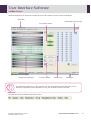
1
User Manual
Software version V4.XX
For further assistance,
please contact IDS Technical Support:
Tel: 0191 519 6153
Fax: 0191 519 0760
Email: [email protected]
IDS FRANCE S.A., 42 rue Stéphane Mazeau, 21320 POUILLY-EN-AUXOIS, FRANCE
IDS Ltd 10 Didcot Way, Boldon Business Park,
Boldon, Tyne and Wear, NE35 9PD
Tel: 0191 519 0660
Revisions
Date
Description
Version
02/21/2008
Revision A
V 3.03
Stamp
SECTION 1
SECTION 2
SECTION 3
SECTION 4
SECTION 5
OPERATING PRINCIPLE
USE SECTION
MESSAGES
MAINTENANCE
PROBLEMS
AND CORRECTIVE ACTION
APPENDIX I
WASTE DISPOSAL
APPENDIX II
DISINFECTING THE
DEVICE APPENDIX III DISPOSAL OF THE
MEDICAL DEVICE
Attached document:
Connection Protocol, revision C
10/21/2008
Revision B
V 3.12
Replacement of 3x3 with IDS-iSYS.
Replacement of BIOCODE-HYCEL by IDS.
SECTION 1
SECTION 2
SECTION 3
SECTION 4
SECTION 5
OPERATING PRINCIPLE
USE
MESSAGES
MAINTENANCE
PROBLEMS
AND CORRECTIVE ACTION
APPENDIX I
WASTE DISPOSAL
APPENDIX II
DISINFECTING THE
DEVICE APPENDIX III DISPOSAL OF THE
MEDICAL DEVICE
Attached document:
Connection Protocol, revision D
IDS-iSYS User Manual - Rev C1 (08/07/2009)
Software version V4.XX
R1
Revisions (Continued)
Date
Description
Version
02/26/2009
Revision C
V 4.03
SECTION 1
SECTION 2
SECTION 3
SECTION 4
SECTION 5
SECTION 6
APPENDIX I
APPENDIX II
DEVICE
APPENDIX III
Stamp
OPERATING PRINCIPLE
USER INTERFACE
SOFTWARE
USE
MESSAGES
MAINTENANCE
PROBLEMS AND
CORRECTIVE ACTION
WASTE DISPOSAL
DISINFECTING THE
DISPOSAL OF THE
MEDICAL DEVICE
APPENDIX IV
IDS-iSYS CUVETTES
Attached document:
Connection Protocol, revision E
08/07/2009
Revision C1
General review of the terminology in all sections
and appendices of revision C.
SECTION 1
SECTION 2
SECTION 3
SECTION 4
SECTION 5
SECTION 6
APPENDIX I
APPENDIX II
THE
V 4.03
OPERATING PRINCIPLE
USER INTERFACE
SOFTWARE
USE
MESSAGES
MAINTENANCE
PROBLEMS AND
CORRECTIVE ACTION
WASTE DISPOSAL
DECONTAMINATING
ANALYSER
DISPOSAL OF THE
ANALYSER
APPENDIX IV
IDS-iSYS CUVETTES
Attached document:
Connection Protocol, revision E
APPENDIX III
IDS-iSYS User Manual - Rev C1 (08/07/2009)
Software version V4.XX
R2
Preface
Special precautions
The safety precautions specific to certain handling procedures described throughout the user manual are
indicated in the following form:
Important notice
!
Precaution which MUST be respected
!
Presence of a potential risk
!
Special Precautions
IDS-iSYS User Manual - Rev C1 (08/07/2009)
Software version V4.XX
P1
Preface
This instruction manual is to be used in conjunction with
the
in vitro diagnostic analyser and must be read before
installing or using the analyser.
The
in vitro diagnostic analyser must only be used
by personnel trained by approved IDS staff.
The purpose of the user manual is to explain:
•
•
•
The way the analyser works.
How to use it in routine working practice.
The preventive maintenance required.
User Manual was produced on the 8th July 2009, for the software version:
Revision C1 of the
•
V 4.03
The manual comprises the following sections and appendices:
Section 1:
Section 2:
Section 3:
Section 4:
Section 5:
Section 6:
Appendix I:
Appendix II:
Appendix III:
Appendix IV:
Operating Principle
User Interface Software
Use
Messages
Maintenance
Problems And Corrective Action
Waste Disposal
Decontaminating The Analyser
Disposal Of The Analyser
IDS-iSYS Cuvettes
Rev C1
Rev C1
Rev C1
Rev C1
Rev C1
Rev C1
Rev C1
Rev C1
Rev C1
Rev C1
Attached document: Protocol for connection, revision E
!
If the analyser is not used in accordance with the recommendations provided in this
manual, the level of performance offered by the analyser may be impaired and the
results generated may be incorrect.
IDS-iSYS User Manual - Rev C1 (08/07/2009)
Software version V4.XX
P2
Preface
List of
symbols used on the analyser
Manufacturer.
In vitro diagnostic medical device.
Consult the instructions for use.
Caution recommended: see Safety Precautions.
Risk of biological contamination.
Risk of crushing injury.
Serial number.
Electrical and electronic waste: dispose of in accordance with current
country-specific laws.
High temperature.
Risk of LED radiation.
Risk of hand injury.
IDS-iSYS User Manual - Rev C1 (08/07/2009)
Software version V4.XX
P3
Table of Contents
Section 1: Operating Principle
1
1-1 Field of Use
1-2 General Overview
1-3 Characteristics
1-4 Installation
1-4-1 Environment
1-4-2 Electricity supply
1-4-3 Connections
1-5 Operating Principles
1-5-1 Absorbency measurements
1-5-2 Potentiometry measurements
1-5-3 Luminescence measurements
1-6 Safety Precautions
1-6-1 General precautions
1-6-2 Special precautions
2
3
6
9
9
9
10
11
11
13
15
16
16
16
Section 2: User Interface Software
17
2-1 Structure of the Software
2-2 Main Screen
2-3 Menus
2-3-1 FILE menu
2-3-2 SESSIONS menu
2-3-3 DATA menu
2-3-4 MAINTENANCE menu
2-3-5 SET-UP menu
2-3-6 MANAGEMENT OF LOTS menu
2-3-7 HELP menu
2-4 Function Keys
18
19
25
25
26
27
28
29
30
30
31
IDS-iSYS User Manual - Rev C1
Software version V4.XX
Table of Contents
i
Table of Contents
Section 3: Use
32
3-1 Start up
3-1-1 Initial Start up
3-1-2 Start up from standby mode
3-2 Installation of Reagents
3-2-1 Colour codes associated with reagent positions in the reagent compartment.
3-3 Installation of Ancillary Reagents
3-3-1 Installation of internal ancillary reagents
3-3-2 Installation of external ancillary reagents
3-3-3 Installation of IDS-iSYS cuvettes
3-4 System Performance Checks (Immunoassay only)
3-4-1 Programming the qualification profile
3-4-2 Programming the automatic qualification profile
3-4-3 Management of results
3-5 Programming Calibrations and Controls
3-6 Loading of Calibrators, Controls or Samples in the Sample Tray
3-6-1 Installation using a barcode
3-6-2 Installation without barcode
3-6-3 Colour codes associated with sample positions
3-7 Programming Samples
3-8 Assays
3-8-1 Performing assays
3-8-2 Adding samples during an assay
3-8-3 Adding or replacing a reagent during an assay
3-8-4 Releasing an alarm during an assay
3-9 Adding an Emergency (STAT) Sample
3-10 Results
3-10-1 Result of a calibration
3-10-2 Results of controls
3-10-3 Sample results
3-10-4 Work list results
3-11 Messages Associated with Results
3-12 Results Storage
3-13 Quality Control Management
3-13-1 Cumulative analysis
3-13-2 Westgard rules
3-14 Switching the Analyser Off
3-15 Switching the Analyser Off Completely
33
33
33
34
38
39
40
41
42
43
43
44
44
45
48
48
50
51
52
53
53
54
54
55
56
57
58
61
62
62
64
67
68
68
70
72
73
Section 4: Messages
74
4-1 Messages Associated with Calibrations
4-2 Messages Associated with Calibration Controls
4-3 Messages Associated with Results
4-4 Warning Messages
4-5 Error Messages
75
77
78
81
82
IDS-iSYS User Manual - Rev C1
Software version V4.XX
Table of Contents
ii
Table of Contents
Section 5: Maintenance
83
5-1 Daily Maintenance
5-1-1 General Maintenance
5-1-1-1 Cleaning the reagent compartment and Plexiglas®
5-1-1-2 Cleaning the sample tray and Plexiglas®
5-1-1-3 External cleaning of the probe
5-1-1-4 Decontamination of the probe
5-1-2 Biochemistry-ISE Maintenance
5-1-2-1 Cleaning cycle for selective electrodes
5-2 Weekly Maintenance
5-2-1 General Maintenance
5-2-1-1 Cleaning the reagent compartment and Plexiglas®
5-2-1-2 Cleaning the sample tray and Plexiglas®
5-2-1-3 Cleaning the rinsing well
5-2-1-4 Cleaning the reagent barcode reader mirror
5-2-1-5 Checking dilutors and IDS-iSYS System Liquid pumps
5-2-1-6 Cleaning the solid waste chute
5-2-2 Biochemistry-ISE Maintenance
5-2-2-1 Cleaning the selective electrodes injection well
5-2-3 Immunoassay Maintenance
5-2-3-1 Flushing the IDS-iSYS Triggers and IDS-iSYS Wash tubing
5-3 Monthly Maintenance
5-3-1 General Maintenance
5-3-1-1 Cleaning the IDS-iSYS System Liquid pump shafts
5-3-1-2 Cleaning the liquid waste pump shaft
5-3-1-3 Cleaning the IDS-iSYS D-Sorb pump and level sensor shafts
5-3-1-4 Cleaning the liquid waste level sensor
5-3-1-5 Checking lamp intensity
5-3-2 Biochemistry-ISE Maintenance
5-3-2-1 Cleaning the Standard A and Waste pump shafts
5-3-3 Immunoassay Maintenance
5-3-3-1 Cleaning the IDS-iSYS Wash pump and level sensor shafts
5-4 Analyser Interventions
5-4-1 Replacement of lamp
5-4-2 Replacement of probe
5-4-3 Replacement of primary fuses
5-4-4 Replacement of secondary fuses
5-4-5 Replacement of IDS-iSYS Wash Solution pump (Immunoassay)
5-4-6 Replacement of IDS-iSYS System Liquid pump
5-4-7 Replacement of liquid waste pump
5-4-8 Replacement of IDS-iSYS D-Sorb pump
5-4-9 Removal of the on-board IDS-iSYS Cuvettes cube
5-4-10 Replacement of Standard A or Waste pumps
84
85
85
85
86
86
86
86
87
88
88
88
89
89
89
90
90
90
91
91
92
92
92
92
93
93
94
94
94
95
95
96
96
98
99
100
101
101
101
102
102
103
Section 6: Problems & Corrective Action
104
6-1 Resolving Errors in Cartridge Check System (CCS)
6-2 Resolving Errors in Selective Electrodes
105
107
IDS-iSYS User Manual - Rev C1
Software version V4.XX
Table of Contents
iii
Table of Contents
Appendices
109
A-1 Waste Disposal
A-2 Decontaminating the Analyser
Cleaning/Decontaminating Declaration
A-3 Disposal Of the Analyser
A-4 IDS-iSYS Cuvettes
A4-1 List of symbols used on the IDS-iSYS Cuvettes cube
A4-2 Storage of the IDS-iSYS Cuvettes cube
110
111
112
113
114
114
114
IDS-iSYS User Manual - Rev C1
Software version V4.XX
Table of Contents
iv
Section 1:
Operating Principle
Section 1
Operating Principle
1
1-1 Field of Use
1-2 General Overview
1-3 Characteristics
1-4 Installation
1-4-1 Environment
1-4-2 Electricity supply
1-4-3 Connections
1-5 Operating Principles
1-5-1 Absorbancy measurements
1-5-2 Potentiometry measurements
1-5-3 Luminescence measurements
1-6 Safety Precautions
1-6-1 General precautions
1-6-2 Special precautions
IDS-iSYS User Manual - Rev C1
Software version V4.XX
2
3
6
9
9
9
10
11
11
13
15
16
16
16
Operating Principle
1
Operating Principle
1-1 Field of Use
is an in vitro diagnostic analyser. It enables Immunoassay, Biochemistry and Coagulation1 assays to
be carried out on a single analytical platform:
•
Immunoassay.
• Bone and Growth.
• Infectious Diseases.
• Hypertension.
• Autoimmunity.
•
Biochemistry.
• Substrates.
• Enzymes.
• Electrolytes.
• Specific Proteins.
•
Coagulation.
• Chronometric tests.
• Chromogenic substrates.
• Immunoassays.
The analyser must only be used by trained personnel working in compliance with the safety precautions set
out in this manual (see Section 1-6-1, page 16) and good laboratory practice (GLP).
1
Coagulation version available during 2010.
IDS-iSYS User Manual - Rev C1
Software version V4.XX
Operating Principle 1-1
2
Operating Principle
1-2 General Overview
is an in vitro diagnostic analyser. It enables Immunoassays, Biochemistry and Coagulation assays to
be carried out on a single analytical platform:
Individual assays are carried out in disposable cuvettes which are automatically loaded onto a carousel.
Asynchronous management allows each cuvette to be processed individually and transferred to the relevant
reaction modules positioned around the carousel.
The cuvette is able to ensure compatibility in all three fields. The measurements specific to each discipline are
carried out directly in the reaction cuvette:
•
•
•
Luminescence measurements carried out in the luminometer (Immunoassay).
Absorbancy measurements carried out continuously by the spectrophotometer (Biochemistry).
Optical measurements for detection of a clot in the chronometer (Coagulation).
Designed for continuous loading, the analyser works on a smaple-by-sample basis. There are several
configurations available:
•
•
•
Immunoassay and Biochemistry.
Biochemistry and Coagulation.
Immunoassay, Biochemistry and Coagulation.
For Biochemistry (as an option), the analyser can be fitted with a module using selective electrodes (ISE) to
determine Sodium, Potassium and Chloride levels.
IDS-iSYS User Manual - Rev C1
Software version V4.XX
Operating Principle 1-2
3
Operating Principle
1-2 General Overview (continued)
With all modules fitted the analyser comprises the following key components:
9
3
7
4
8
5
1
6
2
1.
A refrigerated reagent compartment, consisting of 15 rails containing the Immunoassay, Biochemistry or
Coagulation racks as well as a specialised rack for chronometric reagents.
2.
A sample tray with 64 positions for samples, calibrators and controls.
3.
A pipetting arm that pipettes both reagents and samples.
4.
For Biochemistry configurations, an optional ISE module with selective electrodes for the simultaneous
determination of Sodium, Potassium and Chloride levels.
5.
A thermo-regulated carousel set at 37°C with 90 positions for disposable cuvettes. Incorporated into the
carousel is the spectrophotometer, used for measuring absorbancy from certain Immunoassay,
Biochemistry and Turbidimetry reactions.
6.
An automatic cuvette loader, taking 960 cuvettes at a time (pre-formed as a cube).
7.
Two modules for chronometric measurements (Coagulation version).
8.
A luminometer measuring luminescence in Immunoassay reactions (Immunoassay version).
9.
Two or four washers (depending on configuration) for washing magnetic particles (Immunoassay version).
Two barcode readers (one located on the front face of the analyser, the other integrated into the reagent
compartment) identify samples, ancillary reagents and reagent cartridges supplied by IDS.
IDS-iSYS User Manual - Rev C1
Software version V4.XX
Operating Principle 1-2
4
Operating Principle
1-2 General Overview (continued)
The reagent cartridges are stored in the refrigerated reagent compartment between 12 and 15°C while the
analyser is operating, and between 8 and 10°C in standby mode.
Depending on the configuration of the analyser, up to 15 Immunoassay parameters can be programmed
simultaneously or up to 36 Biochemistry parameters or a combination of both, up to the maximum number of
positions available.
For Immunoassays, the analyser only uses reagents supplied by IDS and its partners. For Biochemistry, it is
possible to use reagents available from suppliers other than IDS, however these reagents will not be managed
using the barcode system, and the information required for traceability must be manually programmed by the
operator.
If reagents other than those marketed by IDS and its partners are used IDS takes no responsibility for the
validity of results obtained. It is the responsibility of the operator to ensure any non-IDS reagents are optimised
and validated for use on the analyser.
Samples and reagents are aspirated using a probe equipped to detect liquid level using capacitance. The
sample and reagents are pipetted in accordance with the validated parameters for each assay and transferred
into a cuvette where the reaction takes place. Between each sample, the probe is rinsed internally and
externally in order to eliminate any risk of contamination.
Immunoassays:
The cuvettes are transferred to the washer module where magnets hold the solid phase (magnetic particles)
whilst washing takes place. The cuvette is then transferred to the luminometer where trigger reagents are added
to produce luminescence. When measurement is complete, cuvettes are automatically ejected into a re-usable
solid waste tray.
Biochemistry assays:
Photometric changes taking place in the reaction are measured continuously by the spectrophotometer.
The analyser is connected to a computer via an Ethernet link.
The software is able to programme the analyser workload and carry out the following functions:
•
•
•
•
•
•
Management of lots of reagents, calibrators and controls.
Quality controls (Levey-Jennings and Westgard).
Management of ancillary reagents.
Operator traceability.
Transfer of results to a centralised computer system.
Printing, storing and traceability of results.
IDS-iSYS User Manual - Rev C1
Software version V4.XX
Operating Principle 1-2
5
Operating Principle
1-3 Characteristics
Analyser
System
•
•
•
Multidiscipline Biochemistry analyser (ISE as an option), Immunoassay
and Coagulation.
Continuous loading.
Configurations:
• Biochemistry (ISE) + Immunoassay (4 washers).
• Biochemistry (ISE) + Immunoassay (2 washers) + Coagulation (2
chronometric modules).
• Biochemistry (ISE) + Coagulation (2 or 4 chronometric modules).
Analyser Physical
Characteristics
•
•
•
•
Analyser dimensions:
Overall dimensions:
Weight:
Computer System:
Throughput
•
•
•
•
•
According to configuration.
Biochemistry + ISE
360 tests/hour.
Immunoassay
Up to 120 tests/hour (Assay dependent).
Coagulation
60 tests/hour (2 chronometric modules).
120 tests/hour (4 chronometric modules).
Number of tests on line
•
50 Biochemistry + 3 tests ISE, 15 Immunoassay or10 Coagulation.
Biochemistry detection
•
•
•
Spectrophotometer with interferential filters.
Wavelengths: from 340 to 620 nm.
Halogen lamp (optical fibre transmission).
Immunoassay detection
•
•
Chemiluminescence.
Luminometer.
Coagulation detection
•
•
Optic detection of clot.
Bi-chromatism.
Selective electrodes module
(ISE)
•
•
•
Determination of Sodium, Potassium, Chloride levels.
Direct potentiometry on serum.
Indirect potentiometry on urine (automatic pre-dilutions).
Samples
•
•
Serum, plasma or urine.
Primary tubes 5 mL (13 x 75 mm), 7 mL (13 x 100 mm).
10 mL (16 x 75 mm).
Secondary tubes (13 x 75 mm).
Paediatric tubes.
500 µL cups (ref. IS-SC105) and 1.5 mL cups (ref. IS-SC115).
64 positions for samples, calibrators and controls.
Liquid level detection by capacitance.
Clot detection.
Dilutions and automatic pre-treatments.
•
•
•
•
•
•
•
Barcode readers
•
•
IDS-iSYS User Manual - Rev C1
Software version V4.XX
L 105 cm x H 70 cm x W 75 cm.
L 124 cm x H 110 cm x W 71 cm.
103 kg.
L 60 cm x H 40 cm x W 50 cm.
Reader on front face for barcode identification of samples, cuvettes
and ancillary reagents.
Integrated reader for reagents barcode.
Operating Principle 1-3
6
Operating Principle
1-3 Characteristics (continued)
Reagent compartment
•
•
•
Sample volume (µL)
•
•
•
Reagent volume (µL)
•
•
•
Reaction volume (µL)
Pipetting system
•
Spectrophotometer
•
•
•
•
•
Luminometer
•
•
Reaction carousel
•
•
•
Cuvette loader
•
•
•
Common liquid consumables
•
•
•
•
Waste collection
•
•
Power supply
•
•
•
IDS-iSYS User Manual - Rev C1
Software version V4.XX
•
•
•
•
15 rails, each of which can hold:
• 1 x Immunoassay cartridge.
• 3 x 45 mL Biochemistry Reagent.
• 6 x 20 mL (or 5 mL) Biochemistry Reagent.
Storage at 12-15°C whilst operating.
Internal storage between 8-10°C in standby mode.
Immunoassay: from 4 to 300 µL.
Biochemistry: from 4 to 50 µL.
Programmable in steps of 0.5 µL.
Biochemistry: from 10 to 400 µL.
Immunoassay: from 10 to 400 µL.
Programmable in units of 1 µL.
Immunoassay and Biochemistry: from 180 to 550 µL.
Pipetting reagents and samples by probe.
Liquid level detection by capacitance.
Preheating of reagents/samples.
Internal and external rinsing between each pipetting of sample.
Spectrophotometer with interferential filters.
6 wavelengths available: 340, 405, 500, 540, 580 and 620 nm.
Halogen lamp. Transmission by fibre optic.
Linearity: Up to 3 OD.
Optic path of cuvettes: 0.7 cm.
Wavelengths: from 300 to 500 nm.
Linearity: Up to 10 Million RLU.
Thermo regulated at 37°C.
90 positions for disposable cuvettes.
Automatic cuvette supply by cuvette loader.
Loader for cube of cuvettes.
Contains 960 disposable cuvettes.
Thermostatically controlled.
IDS-iSYS System Liquid (5 litre containers).
IDS-iSYS Wash (10 litre containers).
IDS-iSYS D-Sorb (1 litre containers).
Immunoassay only: IDS-iSYS Triggers A & B (250 mL each).
10 litre container for liquid waste posing a biological risk.
Solid waste (cuvettes) disposed of in re-usable container.
Voltage: 220 - 240 V.
Frequency: 50 - 60 Hertz.
Maximum power consumed: 1000 VA.
Operating Principle 1-3
7
Operating Principle
1-3 Characteristics (continued)
Selective electrodes module (ISE) (optional)
Principle
•
•
•
Sample
•
•
Measurement using specific electrodes for Sodium, Potassium and
Chloride levels.
Direct potentiometry on serum and plasma.
Indirect potentiometry on urine.
Serum, plasma sampled on sodium/lithium heparin or lithium (volume
taken: 70 µL).
Urine automatically pre-diluted to 1/10.
Precision
•
•
•
Serum
Na + CV < 1.5% (100 – 160 mmol/L).
K+
CV < 2%
(3.0 – 6.0 mmol/L).
Cl - CV < 2%
(80.0 – 120.0 mmol/L).
Cycle time
•
•
Serum
Urine
30 seconds.
60 seconds.
Computer system: Minimum configuration required
Operating system
•
•
•
Windows XP Pro Service Pack 2.
Windows Vista Service Pack 1.
English.
Microprocessor
•
Type Sempron 3100 or equivalent.
Live memory
•
1 Gb.
Hard disk
•
80 Gb.
Ethernet
•
2 independent Ethernet network adaptors.
Ports
•
•
USB ports (min 2 one of which at front).
Serial port for connection to centralised computer system.
Input devices
•
•
Keyboard (country specific).
Mouse.
Screen
•
Monitor. Speakers integrated.
Screen resolution
•
1024 x 768 pixels.
Peripherals
•
Reader – CD writer.
IDS-iSYS User Manual - Rev C1
Software version V4.XX
Operating Principle 1-3
Operating Principle 1-3
8
Operating Principle
1-4 Installation
1-4-1 Environment
The packaging of the IDS-iSYS has been designed to prevent any damage occurring during transportation.
The analyser can be stored in its original packaging under the following conditions:
Storage temperature 10-40°C.
Relative humidity 70% non condensing.
Duration 2 months.
A satisfactory installation site is essential for the analyser to function correctly.
•
•
•
The user must ensure compliance with the conditions required in terms of environment and electricity supply in
order to maintain the performance of the analyser and to guarantee safe use for the operator.
Environmental conditions required:
•
•
•
•
•
•
•
•
The analyser must not be exposed to direct light.
A clean and ventilated air environment.
The analyser must be placed on a flat work surface, capable of supporting its weight (103 kg) without
significant vibration.
The surrounding temperature must be between 15°C and 30°C. Temperature fluctuations during analyses
must not exceed ± 2°C.
Relative humidity must be below 70% (non-condensing).
The analyser must not be installed under an air-conditioning unit.
Clearance of at least 15 cm must be provided at the rear, front, left and right of the analyser to allow
evacuation of heat produced by the apparatus.
The analyser must not be installed near strong sources of electromagnetic radiation and electrical
interference (e.g. refrigerators).
Physical characteristics of the analyser:
•
•
•
•
Dimensions of the analyser
Overall dimensions
Weight
Computer system
L 105 x H 70 x W 75 cm.
L 124 x H 110 x W 71 cm.
103 kg.
L 60 x H 40 x W 50 cm.
1-4-2 Electricity supply
The electricity supply must meet the following conditions:
•
•
•
Voltage
220 - 240 V.
Frequency
50 - 60 Hz.
Maximum power consumed 1000 VA.
If necessary, the installation of a regulated electrical supply may be required.
!
In order to protect the analyser’s electrical safety (in accordance with standards), it is
essential to check that the associated peripheral computer equipment (external printer and
computer) is earthed.
IDS-iSYS User Manual - Rev C1
Software version V4.XX
Operating Principle 1-4
9
Operating Principle
1-4 Installation (continued)
In the event of prolonged storage, the analyser performance must be checked. The unpacking, installation and
initial qualification of the analyser must only be carried out by a qualified IDS representative.
1-4-3 Connections
Fluidic connections
The fluidic connections are located on the right hand side of the analyser. The tubing is identified by a colour
code.
Description
Colour code
Field
IDS-iSYS System Liquid
White.
All.
IDS-iSYS Wash Solution
Blue.
Immunoassay.
Liquid Waste
Red.
All.
IDS-iSYS D-Sorb
Black.
All.
•
•
•
Connect the tubing corresponding to the colour code to the right hand side of the analyser by applying a
quarter turn to the screw.
Install the tubing into each of the respective containers.
Connect the volume detection devices for IDS-iSYS Wash, IDS-iSYS D-Sorb Solution and Liquid Waste.
!
For the Biochemistry or Coagulation analyser configurations, the IDS-iSYS Wash solution is not
used. Do not connect any tube to the blue connector.
Electrical connections
!
For the Biochemistry analyser configurations, use only the IDS-iSYS System Liquid
reference R5H135A.
The electrical connections are located on the left hand side of the analyser.
• Connect the analyser to the PC via the Ethernet cable.
• Connect the mains supply cable.
IDS-iSYS User Manual - Rev C1
Software version V4.XX
Operating Principle 1-4
10
Operating Principle
1-5 Operating Principles
Depending on the type of analysis, the
•
•
•
•
uses the following measurement principles:
Luminescence measurements carried out in the luminometer (Immunoassay).
Absorbancy measurements carried out continuously by the spectrophotometer.
Potentiometry measurements made by the selective electrodes (ISE).
Optic detection of clot by chronometer.
1-5-1 Absorbancy measurements
Samples and reagents are aspirated in accordance with the validated parameters for each assay and are
transferred into a cuvette where the changes in absorbancy (or optical density) will be monitored in the course
of the reaction taking place.
Photometric measurements are carried out in the reaction cuvette (maximum interval between two consecutive
measurements is 25 seconds).
These measurements are carried out at the wavelength specific to the analysis, defined in the parameters, by
automatic selection of the appropriate interferential filter.
In monochromatic light and at constant temperature, the relationship between absorbancy (or optical density OD) and the concentration of the analyte is provided by the BEER-LAMBERT law:
OD = ε l C
with OD = Log
I0
Where:
I
• I0
Light flow at cuvette entrance.
• I
Light flow at cuvette exit.
• ε
Molar extinction coefficient of the analyte (in L.mol -1.cm -1).
• l
Optical pathway (cm).
-1
• C Concentration of analyte (Mol.L ).
•
Absorbancies are measured with an optical pathway of 0.7 cm and corrected for an optical pathway of 1 cm.
Depending on the type of assay defined in the analytical configuration for each set-up, the following absorbancy
measurements are used in the calculations:
•
•
•
Terminal Point
Delta Terminal Point
Kinetic
Uses the last absorbancy and the first absorbancy.
Calculation of the difference between the first and the last absorbances.
Calculation of the slope by linear regression over the absorbancies measured.
Calculation of enzymatic activities using the formula:
Activity =
Where:
• VT =
• VE =
• l =
• ε =
VT x ∆ OD/min x 1000
Total volume.
VE x l x ε
Sample volume.
Optical pathway (1 cm).
Molar extinction coefficient of analyte (in L.mol -1.cm -1).
IDS-iSYS User Manual - Rev C1
Software version V4.XX
Operating Principle 1-5
11
Operating Principle
1-5 Operating Principles
Comment:
In the set-up, the factor entered is equal to ε x 100.
The results are calculated either in relation to a calibration, or multiplied by a factor.
The function used for the calibration is fixed in the analytical configuration. The functions available are:
•
•
•
•
•
•
•
Linear regression.
Linear interpolation.
Polynomial function degree 2.
Polynomial function degree 3.
Polynomial function degree 4.
Cubic Spline.
The calibrations and controls can be programmed on demand or automatically managed in terms of frequency
by the analyser.
A request for calibration is automatically accompanied by a request to perform QC control.
Requests for calibrations and controls can be made at any time. If the analyser is in the process of carrying out
the assay, the calibrations and controls take place prior to the analyses requested on the samples.
IDS-iSYS User Manual - Rev C1
Software version V4.XX
Operating Principle 1-5
12
Operating Principle
1-5 Operating Principles (continued)
1-5-2 Potentiometry measurements
The electrolytes in blood are traditionally measured using flame photometry. In this method, the sample, diluted
with a known concentration of a reference ion (usually lithium or caesium), is vaporised then passed through a
flame which causes excitation of the cations. The energy is re-emitted in the form of a light with a different
frequency; with the amplitude of the emission being proportional to the ion concentration in the sample. The
development of organic compounds selective to sodium, potassium, chlorides and other electrolytes has led to
the development of sensors capable of taking direct measurements in biological fluids.
The module for measuring sodium, potassium and chloride electrolytes in the
electrode technology, as shown in the diagram below:
employs selective
Sample tube
Air bubble detector
Signal to microprocessor
Na + Electrode
(Crown Ether)
Na + potential measure (mV)
K + Electrode
(Valinomycin)
K + potential measure (mV)
Cl - Electrode
Flow-through
membrane assembly
Bubble detector
Pump tube
Separating air bubble
Standard
Cl - potential measure (mV)
Reference electrode body
Ag/AgCl Electrode
3.5 M KCl
Signal to microprocessor
Ionic contact through 3.5 M KCl
internal filling solution
Membrane
To pump
Sodium electrode
The fluid circuit from the sodium electrode has a selective PVC tube specially formulated to be specifically
permeable to sodium ions.
Potassium electrode
The fluid circuit for the potassium electrode has a plastic tube in which valinomycin is incorporated as the
selective element.
Chloride electrode
The fluid circuit for the chlorides electrode has a plastic tube specially designed to recognise chloride ions.
IDS-iSYS User Manual - Rev C1
Software version V4.XX
Operating Principle 1-5
13
Operating Principle
1-5 Operating Principles (continued)
1-5-2 Potentiometry measurements (continued)
The potential of each electrode is measured in comparison with a stable voltage established by the reference
electrode Ag/AgCl. A selective electrode develops a voltage which varies according to the concentration of the
ion to which it responds. The relationship between the voltage developed and the ionic concentration is
logarithmic and is expressed by the NERNST equation:
•
E = ERT
0 + log ( α C)
nF
Where:
• E =
• E0 =
• RT/NF
• log =
• α
=
• C =
Potential of the electrode in the sample.
Potential developed under standard conditions.
=
Constant dependent on temperature, referred to as "slope".
Decimal logarithm function.
Activity coefficient of the ion measured in the solution.
Concentration of the ion measured in the solution.
•
A comparison method is used. Firstly, the module measures the potentials developed by the sample passing in
front of the electrodes. A measurement is then taken on Calibrator A. The difference between the two potentials
is a logarithmic function of the concentration of the ions measured in the sample, divided by their respective
concentration in the Calibrator. As the differences of potentials and concentrations in sodium, potassium and
chloride ions of the Calibrator are known, the ionic concentrations of the sample can be calculated, using the
NERNST equation:
Or
E - E0
C)
= S log (Cx /
(E - E0) / S
Cx = CS x 10
Where:
• E =
Potential of the electrode in the sample.
• E0 =
Potential developed by the electrode in the solution of Calibrator.
• S =
Slope of the electrode calculated during calibration.
• Cx =
Concentration of the ion in the sample.
• CS =
Concentration of the ion in the solution of Calibrator.
•
The slope "S" is determined during calibration with the solutions of Calibrators A and B whose concentrations
are known. When a calibration is carried out, the slope is calculated from the difference between the second
measurement of Calibrator A and the measurement of Calibrator B. An excessive deviation or excessive
background noise measurements are indicated with error messages accompanying the printout of the results.
IDS-iSYS User Manual - Rev C1
Software version V4.XX
Operating Principle 1-5
14
Operating Principle
1-5 Operating Principles (continued)
1-5-3 Luminescence measurements
By-products of luminescent acridinium esters are used as detection markers (DMAE - dimethylethanolamine).
The acridinium esters emit light after reacting with hydrogen peroxide and an alkaline solution. IDS-iSYS Trigger
A contains hydrogen peroxide in a dilute acid medium, and IDS-iSYS Trigger B contains a solution of dilute
sodium hydroxide. The analyser automatically injects trigger solutions A and B into the reaction cuvette, which
results in the oxidation of the ester into an excited form. The return to a stable state is accompanied by the
emission of light which is measured and is expressed in relative light units (RLU) by the luminometer integrated
in the analyser.
Assays are carried out using either a one-site or two-site method.
One-site (competitive) method assay
The assay is based on competition between an unknown quantity of analyte in a sample with labelled analyte
in the kit.
In a sample where no analyte is present, maximum binding of the labelled analyte is possible. With the
increasing analyte concentrations, decreasing binding of labelled analyte is observed. The signal generated by
the labelled analyte in the luminometer is therefore inversely proportional to the concentration of analyte in the
sample.
Two-site (sandwich) method assay
This technique uses two antibodies that detect and bind different portions of the analyte molecule. Incubation of
these antibodies with the sample results in the formation of a ‘sandwich’ complex, where the analyte is
specifically bound by both antibodies. Incubation with coated magnetic particles allows capture of these
complexes. The signal generated by detection of the captured complexes is directly proportional to the
concentration of analyte in the sample.
Generating the master curve and calculation of results
The results are calculated in comparison to a calibration curve.
The specific reference curve (master curve) for a reagent lot is in the file containing all the data for that lot, that
is provided on the CD accompanying the cartridge. This information is registered in the analyser’s database
when the CD is introduced on the controlling computer.
If a new reagent lot is used, this curve must be registered on the database and then adjusted by a 2 point
calibration before sample results can be calculated.
2 point calibration
Analyser-to-analyser variation and different reagent lots will require adjustment of the master curve (calibration).
This is done by assaying two calibrators supplied with the reagent cartridge. The analyser’s software will
automatically perform the data processing to generate a new curve by defining new values for two of the four
parameters considered to be critical.
In practice, the 4 parameters of the reference curve specific to the reagent cartridge lot are loaded in the user’s
analyser via a CD provided with the kit. Calibration of the test must then be requested prior to use. The
calibration is performed and then verified by assaying one or more controls. Subsequent calibrations must be
repeated regularly in accordance with each assay’s instructions for use or as prompted by the analyser.
IDS-iSYS User Manual - Rev C1
Software version V4.XX
Operating Principle 1-5
15
Operating Principle
1-6 Safety Precautions
The
is a multiparameter selective analyser for in vitro assays in clinical biology.
The analyser must only be used by trained personnel in compliance with the following safety precautions and
good laboratory practice (GLP).
1-6-1 General precautions
•
After start up and installation of reagents, cartridges must be left for a period of time before use. For
biochemistry this should be 20 minutes to allow temperature equilibration. For Immunoassay this should be
40 minutes for temperature equilibration and magnetic particle re-suspension.
•
Do not lift the lid while the analyser is running (i.e. during the run cycle). Opening the lid during the run cycle
interrupts the movements of the pipetting arm. Should this occur, analyses under way may be interrupted and
restarted (recycled).
•
Do not place bottles of reagent on the surface of the analyser.
•
While the analyser is in operation, do not touch the analyser stop/start button.
•
Make sure that the reagent and sample racks are clean at all times.
•
The database is automatically backed up once a week. Operators should store back-ups from the computer
onto CD or USB flash drive.
•
Keep documentation of the set-up programmed on the analyser.
•
Only Immunoassay and ancillary reagents supplied by IDS and its partners, can be used on the analyser
(catalogue available on request).
•
To ensure that the cuvette loader functions correctly, only use full cubes of cuvettes. Never install isolated
layers in the loader.
•
In the event of maintenance or an intervention by IDS Service & Support Personnel, the analyser and its
various components must first be cleaned and decontaminated as defined in the Maintenance section
(see Section 5, page 84).
•
Maintenance operations must be carried out at the frequency stipulated for each type of maintenance activity.
As some parts of the analyser are in contact with the biological samples, they must be considered to pose a
potential risk of infection.
•
Validation of non-IDS biochemistry reagents is the responsibility of the user and IDS takes no responsibility
for the validity of results if non-IDS products are used.
•
In order to guarantee the thermo-regulation of the carousel, ambient temperature must be lower than 30°C. If
necessary, provide air conditioning for the site.
1-6-2 Special precautions
The safety precautions specific to certain handling procedures described throughout the user manual are
indicated in the format described in the Preface section.
IDS-iSYS User Manual - Rev C1
Software version V4.XX
Operating Principle 1-6
16
SECTION 2:
User Interface Software
IDS-iSYS User Manual - Rev C1
Software version V4.XX
16
Section 2
User Interface Software
17
2-1 Structure of the Software
2-2 Main Screen
2-3 Menus
2-3-1 FILE menu
2-3-2 SESSIONS menu
2-3-3 DATA menu
2-3-4 MAINTENANCE menu
2-3-5 SET-UP menu
2-3-6 MANAGEMENT OF LOTS menu
2-3-7 HELP menu
2-4 Function Keys
18
19
25
25
26
27
28
29
30
30
31
IDS-iSYS User Manual - Rev C1
Software version V4.XX
User Interface Software
17
User Interface Software
2-1 Structure of the Software
The software provides access to the options and information required to run the analyser.
Various options are available via pull-down menus at the top of the screen.
Access to the software requires a password. Multiple authorisation levels are managed by the system:
•
Operator and Supervisor levels are for laboratory users while all other levels are reserved for IDS Service and
Support personnel. Access to items in the menu is dependent on user level.
Passwords and authorisation levels can be modified later if required.
The user interface application software is run on an external PC using Microsoft Windows™ (XP or Vista). The
PC is linked to the analyser via an Ethernet cable.
The analyser uses embedded software which interprets instructions from the user interface application software
into actions to be performed by the analyser. It also records the data obtained. This data is then sent to the user
interface application software for final result calculation and storage.
In the event of any interruption in the connection with the user interface, this software configuration allows the
analyser to continue to carry out its workload and store the raw data produced. When the connection is
restored, synchronisation will occur automatically without any data loss or interruption to the analytical process.
IDS-iSYS User Manual - Rev C1
Software version V4.XX
User Interface Software 2-1
18
User Interface Software
2-2 Main Screen
When the application is opened and a valid access code entered, the main screen is displayed.
Menu Bar
Standard B Position (ISE)
Information buttons
Reagent Compartment
!
Function buttons
Sample Tray
Status bar
The Standard B position for ISE is present only with 80 positions drawer (diameter 13 mm).
With the 64 positions drawer (diameter 16 mm), this position has been removed.
Menu bar
Provides access to the different pull-down menus.
IDS-iSYS User Manual - Rev C1
Software version V4.XX
User Interface Software 2-2
19
User Interface Software
2-2 Main Screen (continued)
Reagent Compartment
The illustration above shows the reagent compartment with reagents on board.
The racks are automatically identified by the integrated barcode reader when the rack is inserted in the rail.
For each occupied position the following information is displayed:
•
•
•
Test name.
Lot number.
Status of the reagent indicated by a colour code (see Section 3, page 38).
Detailed information for each analyte may be accessed by clicking on the cartridge, in the case of Immunology,
or individual Biochemistry reagents.
Information includes:
•
•
•
•
•
•
•
•
Test name.
Reagent type.
Lot number.
Container number.
Type of container.
Expiry date.
In-use stability.
Available volume and number of tests remaining.
IDS-iSYS User Manual - Rev C1
Software version V4.XX
User Interface Software 2-2
20
User Interface Software
2-2 Main Screen (continued)
Information Application Buttons
Provides access to information regarding the analyser status including :
•
•
•
•
•
•
General status of the apparatus (initialised, standing etc.).
Status of the various modules.
Allowed/forbidden assays depending on the field.
Temperatures : reagent compartment, carousel, ambient.
Status of reagents.
Status of reagent drawer, samples drawer, lid.
The general status is indicated by a colour code:
•
•
•
•
Green = Operational.
Orange = Caution: one of the elements is outside the optimal operating conditions
(for example, temperature).
Red = Error/fault.
Yellow = Analyser not initialised (standing).
Provides information covering the workload requested including:
•
•
•
•
•
Missing reagents required to perform queued assays.
Expired reagents.
Unavailable tests.
Tests stopped during the cycle due to calibration failures, Westgard rules violation
etc.
Automatic requests for calibrations and controls generated by the system.
If messages affecting the current workload appear, the button is displayed in orange
with the number of warning messages indicated.
If automatic requests have been generated, a flashing
icon will appear.
Provides access to the alarms generated by the system:
•
•
Module errors.
Lack of reagents.
An error message is indicated in the ALARM button which is displayed in red and
contains the number of errors identified.
IDS-iSYS User Manual - Rev C1
Software version V4.XX
User Interface Software 2-2
21
User Interface Software
2-2 Main Screen (continued)
Function application buttons
Starts the run cycle.
Accesses calibration and quality control requests.
Displays the current calibration for each on-board lot of reagent.
Provides access to the work list and generated results. Contains profiles sent by the
Laboratory Information System (LIS). The work list contains the details of the profiles
completed or in progress. When the completed profile has been stored, the results are
displayed in the work list until the associated sample is removed. The results are
automatically stored provided the tests complete without any errors/faults.
Allows manual entry of a barcode identifier for samples or reagents in the event of a
misreading by the integrated barcode readers.
Allows access to information regarding the ancillary reagents connected to the
system, and the status of the solid and liquid waste.
The level of each element is displayed. The following detailed information can be
displayed by clicking on the reagent button:
•
•
•
•
•
•
•
Identifier and name of the reagent.
Lot number.
Number of the container in the lot.
Type of container.
Expiry date.
Status of the reagent.
Available volume (or number of cuvettes).
This menu allows the user to manually enter a barcode identifier in the event of
misreading by the integrated barcode reader.
Clicking on the liquid or solid wastes allows the user to confirm emptying.
IDS-iSYS User Manual - Rev C1
Software version V4.XX
User Interface Software 2-2
22
User Interface Software
2-2 Main Screen (continued)
Sample tray
The illustration above shows the samples tray with the positions occupied by:
•
•
•
Calibrators.
Controls.
Samples.
Each position is equipped with a detection sensor. The samples are identified by the barcode reader (on the
front face) prior to loading the sample. Alternatively, barcode identifiers can be entered manually after sample
loading:
Any position of the sample compartment may be used to load a calibrator, a control or a sample.
An icon identifies the type of reagent installed (see Section 3, page 48).
For each occupied position the following options are available:
•
•
•
•
Entry of the identifier and the type of reagent installed (without a barcode).
Programming of the analyses to be carried out.
Results display for controls or samples.
Colour coded analysis status (see Section 3, page 57).
IDS-iSYS User Manual - Rev C1
Software version V4.XX
User Interface Software 2-2
23
User Interface Software
2-2 Main screen (continued)
Status bar
Displays the analyser status, work list and the connection status of the analyser (com flashes blue in normal
activity or red when there is a break in communication).
Status of the analyser.
Number of profiles without associated positions. These profiles will never be
performed. The profiles will be started only when a position is assigned.
Number of completed profiles in the work list.
Number of incomplete profiles in the work list with at least one assay programmed
but not completed.
Number of automatic requests generated by the system. The list can be accessed via
the WARNING window.
IDS-iSYS User Manual - Rev C1
Software version V4.XX
User Interface Software 2-2
24
User Interface Software
2-3 Menus
Other functions are accessed by using the pull-down menus on the interface.
2-3-1 FILE menu
Allows the user to save the database, in addition to the automatic save performed
each week. The saved database contains:
•
•
•
•
•
Analytical configuration.
Personal library.
Calibrations and the quality controls.
Reagent and ancillaries traceability.
Stored results.
The database is saved under the format used in the application.
Allows the user to restore all or part of the saved database, as desired, including:
•
•
•
•
Analytical configuration.
Personal library.
Calibrations and the quality controls.
Stored results.
Allows the user to exit the software.
IDS-iSYS User Manual - Rev C1
Software version V4.XX
User Interface Software 2-3
25
User Interface Software
2-3 Menus (continued)
2-3-2 SESSIONS menu
Allows the user to start up the analyser. All modules will be initialised and
automatically primed. The reading modules are automatically controlled.
Once start-up is complete, the option becomes inactive (grey).
Allows the user to put the analyser into standby mode. In standby mode, the reagents
are stored between 8 and 10°C. For an analyser equipped with the selective
electrodes module (ISE), the Standard A is periodically refreshed.
Access to the work list: (see Section 3-10-4, page 62).
Allows the user to start the run cycle: (see Section 3-8, page 53).
Once the analyser is in assay mode, the option becomes inactive.
This option is active when the analyser is in run cycle.
Allows the user to stop the assay process.
This option is active when the analyser is in run cycle.
Displays information concerning the tests in process. The software displays the time
of processing and when each assay’s results will be available.
Allows the user to view the available volumes and the number of tests for each onboard reagent, before or during the run cycle.
Programming and processing of tests for the reagent Cartridge Check System (CCS).
Simplifies programming of the work list by applying the same profile to
each occupied position.
Management of user access: when an access code is entered, a specific session is
opened. The user’s identifier and the level of authorisation are displayed at the top of
the title bar. Access codes and identifiers are programmed in the SETTINGS menu.
Keep a record of your access codes. If lost, Operator sessions can be opened by
using the code HELP. Each access will be recorded.
IDS-iSYS User Manual - Rev C1
Software version V4.XX
User Interface Software 2-3
26
User Interface Software
2-3 Menus (continued)
2-3-3 DATA menu
Allows access to all the calibrations currently valid for each test in the personal library.
Displays the active calibration of a reagent lot for each test of the personal library.
Allows access to the stored results. When opened, the results are displayed. Various
filters can be applied to display results for a single date, between two dates or for the
entire storage period.
Analysis of quality controls results.
•
•
•
•
LEVEY-JENNINGS: cumulative analysis of the results obtained by
test or by a control lot for a programmable period of time.
WESTGARD: inspection of the control results with selected rules.
History by product: record of the results obtained for each reagent
and for all tests using this reagent.
Printouts: global printouts of Levey-Jennings data.
Records events for:
•
•
•
•
•
•
•
System.
Database.
Access.
Analytical.
Laboratory Information System (LIS) transfers.
Maintenance.
Positive identification.
For use in fail mode: failure to detect samples and reagents.
Allows user to memorise configurations of the reagent compartment, with the positions
of each reagent recorded.
Displays the master curve data recorded in the system (Immunoassay).
Displays the number of assays (calibrations, controls, samples)
performed for each test.
IDS-iSYS User Manual - Rev C1
Software version V4.XX
User Interface Software 2-3
27
User Interface Software
2-3 Menus (continued)
2-3-4 MAINTENANCE menu
Allows selective initialisation of modules.
Allows selective priming of modules.
Allows self-checking of measurement modules.
User maintenances:
•
•
•
•
•
XY adjustment: adjustment of the positions of the probe.
Daily maintenance: table of daily maintenance.
Weekly maintenance: table of weekly maintenance.
Monthly maintenance: table of monthly maintenance.
Maintenance history: allows user to display and print the
maintenance carried out.
Reserved for IDS Service and Support Personnel.
Displays the analyser status (see Section 2-2, page 21).
IDS-iSYS User Manual - Rev C1
Software version V4.XX
User Interface Software 2-3
28
User Interface Software
2-3 Menus (continued)
2-3-5 SET-UP menu
Contains a list of all the tests developed for the analyser.
Selecting one from the list displays the set-up of the test: steps of the assay,
calibrators and controls, handling volumes, incubation time, etc.
Some elements can be modified by the Supervisor (such as units or controls),
others can only be viewed.
Contains a list of tests that can be run on the analyser.
Allows access to the list of all products and suppliers stored in the system.
Allows the user to create an unlimited number of profiles which can be used for
programming.
Allows the operator to personalise the system:
• System: selection of printing options, automatic validation of results,
automatic transfers to the LIS; activation of sound alarms;
programming of automatic start-up and shut-down.
• Languages: selection of user language.
• Operators: programming of access level and user authorisation (name
and access code).
IDS-iSYS User Manual - Rev C1
Software version V4.XX
User Interface Software 2-3
29
User Interface Software
2-3 Menus (continued)
2-3-6 MANAGEMENT OF LOTS menu
Displays reagents used on the system:
•
•
•
•
Personal library: data storage for different reagent lots for the tests in
the personal library for each cartridge the identifier, the lot number, the
expiry date and the remaining number of tests can be displayed.
Preventive alert thresholds: allows programming of the minimum
available number of tests for each assay. When this level is reached,
a preventive alarm is generated.
Trace: traceability of calibrations, controls and results obtained with
each reagent cartridge.
On-board volumes: displays volumes and number of tests for all
on-board reagents and ancillaries.
Lists calibrators used on the system. Allows users to manually input the values for
each lot of calibrator. Allows activation of the calibrator lots used for a specific assay.
Lists controls used on the system. Allows users to enter manually the values of each
lot of control. Allows activation of the control lots used for a specific assay.
Displays data for the lots of ancillaries used with the system. For each ancillary, the
identifier, the lot number, and the expiry date can be displayed.
2-3-7 HELP Menu
Displays information concerning software (for example, specific version).
IDS-iSYS User Manual - Rev C1
Software version V4.XX
User Interface Software 2-3
30
User Interface Software
2-4 Function Keys
The function keys can be used as a shortcut to access the following options from the main screen.
F2
Work list.
F3
Start the run cycle.
F4
Storage.
F5
Calibrations.
F6
Run cycle monitoring.
F8
Status of analyser.
F9
Stop run cycle.
IDS-iSYS User Manual - Rev C1
Software version V4.XX
User Interface Software 2-4
31
SECTION 3:
Use
Section 3
Section 3: Use
32
3-1 Start up
3-1-1 Initial Start up
3-1-2 Start up from standby mode
3-2 Installation of Reagents
3-2-1 Colour codes associated with reagent positions in the reagent compartment
3-3 Installation of Ancillary Reagents
3-3-1 Installation of internal ancillary reagents
3-3-2 Installation of external ancillary reagents
3-3-3 Installation of IDS-iSYS cuvettes
3-4 System Performance Checks (Immunoassay only)
3-4-1 Programming the qualification profile
3-4-2 Programming the automatic qualification profile
3-4-3 Management of results
3-5 Programming Calibrations and Controls
3-6 Loading of Calibrators, Controls or Samples in the Sample Tray
3-6-1 Installation using a barcode
3-6-2 Installation without barcode
3-6-3 Colour codes associated with sample positions
3-7 Programming Samples
3-8 Assays
3-8-1 Performing assays
3-8-2 Adding samples during an assay
3-8-3 Adding or replacing a reagent during an assay
3-8-4 Releasing an alarm during an assay
3-9 Adding an Emergency (STAT) Sample
3-10 Results
3-10-1 Result of a calibration
3-10-2 Results of controls
3-10-3 Sample results
3-10-4 Work list results
3-11 Messages Associated with Results
3-12 Results Storage
3-13 Quality Control Management
3-13-1 Cumulative analysis
3-13-2 Westgard rules
3-14 Switching the Analyser Off
3-15 Switching the Analyser Off Completely
33
33
33
34
38
39
40
41
42
43
43
44
44
45
48
48
50
51
52
53
53
54
54
55
56
57
58
61
62
62
64
67
68
68
70
72
73
IDS-iSYS User Manual - Rev C1
Software version V4.XX
Use
32
Use
3-1 Start up
3-1-1 Initial Start up
•
•
•
•
!
Switch the analyser on by pressing the switch located on the left-hand side to position “1”.
Switch the computer on, then open the software by double-clicking on the IDS-iSYS icon.
Once the software is open, enter your access code to open a session.
Start the analyser by selecting Start up from the session menu:
All modules are initialised and the ancillary reagents are automatically primed.
!
If a new version of the software is detected on the analyser after opening, a message about
downloading this new version to the analyser will appear.
3-1-2 Start up from standby mode
Enter your access code to open a session. The analyser can be programmed to start up automatically at a
selected ‘wake-up’ time.
Use
3-2 Installation of Reagents
IDS-iSYS User Manual - Rev C1
Software version V4.XX
Use 3-1
33
Take care when opening and closing the reagent compartment: rough handling when
opening and closing the drawer may cause the internal reagents to spill.
Access authorised (Drawer unlocked).
Sampling in progress. Access denied (Drawer locked).
(Flashing between red and green) Sampling in less than 2 minutes.
IDS-iSYS User Manual - Rev C1
Software version V4.XX
Use 3-2
34
Use
3-2 Installation of Reagents (continued)
During the run cycle, if a reagent is to be aspirated within 2 minutes, the drawer light flashes
red and green.
!
When opening the reagent compartment during the run cycle, assays which are under way
may be stopped if a reagent was scheduled to be added when the compartment was open.
In the event of this, the rescheduled assays are automatically added to the end of the work
list.
The reagent racks are loaded in the refrigerated compartment.
The reagent cartridges are placed on racks specific to each field.
An Immunoassay reagent rack is designed to hold a cartridge containing all the reagents needed for the test.
Biochemistry reagents are supplied in the form of individual reagent bottles.
Biochemistry reagent racks are designed to contain either 3 x 50 mL bottles or 6 x 20 mL bottles.
Rack IDS1
3 x 50 mL
Rack IDS2
6 x 20 mL
If the reagents have been stored on-board and the analyser has been put into standby mode, the identification
of these reagents will be restored upon start up.
Reagent cartridges can also be installed during the run cycle:
•
•
•
•
•
If access is authorised, open the reagent compartment.
Slide the reagent rack into a rail in the refrigerated reagent compartment until the positioning pin is fully
inserted.
The reagent cartridges are automatically identified by the barcode reader as the rack is inserted in the rail.
On the interface, the reagents are identified and displayed in green with the corresponding lot number.
Repeat for all the racks to be installed on the analyser.
IDS-iSYS User Manual - Rev C1
Software version V4.XX
Use 3-2
35
Use
3-2 Installation of Reagents (continued)
!
If positive identification has failed, the reagent cartridge position is displayed in orange with
“???” instead of the name and lot number.
•
•
•
Should identification fail, repeat the procedure for putting the reagent rack in position.
If the position is still not identified, click on the position.
Select the type of reagent rack installed.
•
To select an Immunoassay rack, click on “IDS Cartridge” and use the keyboard to manually enter the barcode
identifier for the cartridge.
•
The information relating to the Immunoassay reagent cartridge (composition, reagent lots, expiry date, master
curve) is automatically associated with the barcode reading and the position is displayed in green. This
information is also contained in the CD supplied with the kits.
If this information is not available, the position of the reagent is displayed in white with red stripes.
In this case, install the CD supplied with the kit and use the keyboard to re-enter the barcode identifier.
•
•
IDS-iSYS User Manual - Rev C1
Software version V4.XX
Use 3-2
36
Use
3-2 Installation of Reagents (continued)
To select a Biochemistry rack, click on “IDS Rack”. Then select the type of rack:
•
•
For a 3 x 50 mL rack, click on IDS 1.
For a 6 x 20 mL rack, click on IDS 2.
IDS 1
IDS 2
•
Then click on the position and use the keyboard to enter the barcode identifier for the bottle, and select the
reagent installed.
•
The information about the bottle (type of reagent, lot, expiry date) is automatically associated with the
barcode reading. This information is also contained in the CD supplied with the reagents. If the information is
not available, the position of the reagent is displayed in white with red stripes.
In this case, install the CD supplied with the kit.
•
!
Wait for 40 minutes after installing reagent cartridges before starting assays, as the reagent
cartridge temperature must be allowed to equilibrate (20 min for Biochemistry).
IDS-iSYS User Manual - Rev C1
Software version V4.XX
Use 3-2
37
Use
3-2 Installation of Reagents (continued)
3-2-1 Colour codes associated with reagent positions in the reagent compartment.
Rail free.
Reagent correct.
Presence of a rack or reagent detected but not identified.
A calibration will be requested in the next 24 hours.
Preventive alarm threshold reached.
Reagent volume inadequate or reagent expired.
Information associated with the reagent not available.
IDS-iSYS User Manual - Rev C1
Software version V4.XX
Use 3-2
38
Use
3-3 Installation of Ancillary Reagents
On board levels and expiry dates of ancillary reagents are managed by the analyser.
The ancillary reagents comprise:
•
•
•
IDS-iSYS Cuvettes.
Internal ancillary reagents.
External ancillary reagents.
•
Click on
to display the level of ancillary reagents available.
For each solution the current volume is displayed.
The number of IDS-iSYS Cuvettes present in the loader is displayed.
•
If an ancillary reagent is displayed as missing or volume is inadequate (colour code red), install a new
ancillary reagent.
!
!
If the analyser is carrying out an assay, only the IDS-iSYS Cuvettes cube and the IDS-iSYS
System Liquid can be replaced. The other ancillary reagents cannot be replaced until the
analyser has completed the cycle.
Only use IDS products.
IDS-iSYS User Manual - Rev C1
Software version V4.XX
Use 3-3
39
Use
3-3 Installation of Ancillary Reagents (continued)
3-3-1 Installation of internal ancillary reagents
Description
Field
Standard A
ISE.
IDS-iSYS Trigger A
Immunoassay.
IDS-iSYS Trigger B
Immunoassay.
WARNING:
OPENING/CLOSING THE LID
The lid must be opened for this operation. Always handle the lid carefully during
opening and closing and is fully open to ensure it is stable. When the lid is not fully
open there is a risk of it falling.
Take care not to knock the lid during any analyser intervention.
•
•
•
•
•
•
•
•
•
Open the lid fully.
Remove the cap from the new ancillary reagent container.
If necessary, take out the bung and remove the empty container.
Scan the ancillary with the barcode reader.
Install the new bottle in its position identified by colour code.
Install the supply line into the bottle.
Standard A is automatically primed when newly installed. IDS-iSYS Trigger A and B are not automatically
primed, and therefore a manual priming request is required.
If the barcode is not read by the barcode reader, click on the ancillary reagent then use the keyboard to enter
the identifier.
Close the lid.
!
Refer to the catalogue for the product references of the ancillary reagents to be ordered.
IDS-iSYS User Manual - Rev C1
Software version V4.XX
Use 3-3
40
Use
3-3 Installation of Ancillary Reagents (continued)
3-3-2 Installation of external ancillary reagents
Description
Colour code
Field
IDS-iSYS System Liquid
(5 litres)
White.
All.
IDS-iSYS Wash (10 litres)
Blue.
Immunoassay.
IDS-iSYS D-Sorb (1 litre)
Black.
All.
•
•
•
•
•
Remove the lid and level sensor from the container to be replaced.
Scan the new ancillary reagent with the barcode reader.
Put the level sensor in position within the new ancillary reagent for the IDS-iSYS D-Sorb and IDS-iSYS Wash
solutions.
Priming of the IDS-iSYS System Liquid takes place automatically. For other ancillaries, request partial priming
from the menu:
If the ancillary barcode is not read by the barcode reader, click on the ancillary reagent then use the keyboard
to enter the identifier.
!
Refer to the catalogue for the product references of the ancillary reagents to be ordered.
!
For Biochemistry, use only the IDS-iSYS System Liquid reference R5H135A.
IDS-iSYS User Manual - Rev C1
Software version V4.XX
Use 3-3
41
Use
3-3 Installation of Ancillary Reagents (continued)
3-3-3 Installation of IDS-iSYS cuvettes
WARNING:
RISK OF INJURY
Do not place your hand or fingers into the loader.
If necessary, remove the empty IDS-iSYS Cuvettes box.
•
•
•
•
Scan the replacement box with the barcode reader.
Within 10 seconds of the barcode reading, install the IDS-iSYS Cuvettes cube into the loader with the window
to the front.
Remove the protective plastic strip: pull upwards to break the seal and then forwards to remove the protective
strip. Place the protective strip over the cube to protect the window from dust.
If the barcode is not read by the barcode reader, click on the ancillary reagent then use the keyboard to enter
the barcode identifier.
Follow the directions for positioning of the cube in the loader.
Do not remove the protective strip before installing the cube in the loader.
!
Install only full cubes. Never install individual plates. Reassembly of cuvette plates will cause
the analyser to jam.
Correct positioning of the cube of cuvettes in the loader is essential for the automatic cuvette
loading module to function correctly.
The cuvettes are disposable devices.
!
Refer to the catalogue for the product references of the ancillary reagents to be ordered.
IDS-iSYS User Manual - Rev C1
Software version V4.XX
Use 3-3
42
Use
3-4 System Performance Checks (Immunoassay only)
The performance of the analyser must be checked on a daily basis before performing an assay requiring
calibration, controls or samples.
To achieve this, a reagent cartridge known as Cartridge Check System (CCS) is used. Different protocols
are applied to this cartridge in order to determine the functional state of the various analyser modules.
For daily use and acceptance criteria, refer to the CCS cartridge instructions for use (IFU).
3-4-1 Programming the qualification profile
•
From the main screen, select :
The qualification profile menu is displayed.
•
•
If results from a previous profile are present in the list of current results, click on
The results are sent to storage and the list is released for a new profile.
From the drop-down list, select the necessary test and programme the required number of replicates
(see CCS IFU) then click on
•
Repeat the operation for each test required.
•
Click on
•
Start the profile by clicking on
.
.
IDS-iSYS User Manual - Rev C1
Software version V4.XX
.
.
Use 3-4
43
Use
3-4 System Performance Checks (Immunoassay only) (continued)
3-4-2 Programming the automatic qualification profile
The qualification profile can be programmed as part of the automatic start-up of the analyser. The automatic
start-up is programmed in the set-up menu under SYSTEM SETTINGS.
In the SYSTEM SETTINGS window, select the STARTING-UP tab.
•
•
•
•
Click on the box ‘Activate wake-up’.
Check the box ‘Run a QC profile on wake-up’.
The fields for programming the qualification profile are displayed.
From the drop-down list, select the necessary test and programme the required number of replicates
(see CCS IFU) and click
.
•
Repeat the operation for each test required.
•
Click on
!
.
Provided a valid CCS reagent cartridge is present, along with sufficient levels of ancillary
reagents, the analyser will automatically perform the relevant priming and QC profile at the
scheduled ‘wake-up’ time.
3-4-3 Management of results
•
Extract the CCS raw data.
• In the work list, choose the individual CCS results you wish to export, or select ‘All profiles’ when prompted.
This can be done in either the Standard or Tabular views.
• Click the ‘Extract Results’ button.
• Choose the location where you would like to save your raw CCS data file, name the file and click on ‘Save’.
• This will save your raw CCS data in a text file (.txt).
•
Import the data into the EXCEL file provided on the CD.
•
Validate the analyser performance using this data as directed by IDS Service and Support Personnel.
!
Do not perform immunoassays if the analyser performance level is not satisfactory (valid).
Refer to Section 6 of this manual Troubleshooting (see Section 6, page 104).
IDS-iSYS User Manual - Rev C1
Software version V4.XX
Use 3-4
44
Use
3-5 Programming Calibrations and Controls
The frequency of calibrations and controls can be programmed on demand or automatically by the analyser.
Each reagent lot has its own calibration, thus allowing multiple reagent lots of the same analyte on board at the
same time.
A request for calibration is automatically accompanied by a request to include QCs in the assay (QC1 for
Biochemistry) or several QCs depending on the configuration.
!
QC4 is used only for Immunoassays.
Requests for controls can be made as soon as a validated calibration is stored.
Requests for calibrations and controls can be made regardless of calibration status. During the run cycle the
calibrations and the controls take priority over all other tests requested.
From the main screen, click on
.
Programming a Calibration of a New Reagent Lot
•
Click on
alongside the assay to be calibrated. A tick is displayed in the calibration column and in the
appropriate QC column(s).
•
If more than one reagent lot is on-board, when
•
Select the lot to be calibrated, and then click on
and in the appropriate QC column(s).
IDS-iSYS User Manual - Rev C1
Software version V4.XX
is clicked on a new window appears (see below).
. A tick is displayed in the calibration column
Use 3-5
45
Use
3-5 Programming Calibrations and Controls (continued)
Programming a New Calibration for a Reagent
• The resulting screen (see below) shows a list of all tests in the personal library. It also includes the date and
time of the last calibration for the on-board analytes.
• Click on the box in the column Cal in front of the lot to be calibrated. A tick is displayed in the calibration
column and in the QC column(s).
!
Calibrations for several lots of the same reagent can programmed simultaneously.
IDS-iSYS User Manual - Rev C1
Software version V4.XX
Use 3-5
46
Use
3-5 Programming Calibrations and Controls (continued)
Programming Quality Controls for a Reagent Lot
Controls can be performed at any time for the on-board reagent lots provided there is a valid calibration.
•
•
To request a QC1, QC2, QC3 or QC4 quality control, click on the box corresponding to the test to be
performed.
Load the necessary calibrators and controls onto the analyser.
!
If the value of a calibrator or control is not defined for the active lot, a window automatically opens
allowing values to be entered.
!
The current calibration can be displayed for a reagent lot by double - clicking on the lot number or
on the display area (light green area).
IDS-iSYS User Manual - Rev C1
Software version V4.XX
Use 3-5
47
Use
3-6 Loading of Calibrators, Controls or Samples in the Sample Tray
!
Take care when opening and closing the reagent drawer: rough handling when opening and
closing the drawer may cause the internal reagents to spill.
Access authorised (Drawer unlocked).
Sampling under way. Access denied (Drawer locked).
Any position of the sample tray may be used to install samples, calibrators and controls. Each of these have an
associated icon shown in the table below:
Calibrator
Serum, Plasma, Other
Sample
Urine
Control
3-6-1 Installation using a barcode
•
If the light is green, open the drawer.
Calibrators and controls
Scan the barcode with the reader located on the front face. The analyser will beep when the barcode has
been correctly read.
• Within 5 seconds, place in a free position on the rack. If the barcode is recognised, the analyser will beep a
second time. On the interface, the display will indicate that the position has been identified. If no second beep
is heard, the position is considered to be occupied but not identified. In this case, re-start the barcode reading
and installation process.
•
•
•
•
•
•
If the barcode label is illegible, click on
Use the keyboard to enter the barcode identifier.
Select ‘Vial association with samples tray’ and click ‘OK’.
Click on ‘Configure’.
The position is configured.
!
.
For the calibrators and controls supplied by IDS, enter the 12 figures from the barcode: the
product, the lot number, the expiry date as well as the table of corresponding values are
automatically entered.
IDS-iSYS User Manual - Rev C1
Software version V4.XX
Use 3-6
48
Use
3-6 Loading of Calibrators, Controls or Samples in the Sample Tray (continued)
Samples
• Scan the barcode with the reader located on the front face. The analyser will beep when the barcode has
been correctly read.
• Within 5 seconds, place the sample in a free position on the rack. If the barcode is recognised, the analyser
will beep a second time. On the interface, the display will indicate that the position has been identified. If no
second beep is heard, the position is considered to be occupied but not identified. In this case, re-start the
barcode reading and installation process.
•
•
•
•
•
•
•
If the barcode label is illegible, click on
.
Use the keyboard to enter the barcode identifier.
Select ‘Vial association with samples tray’ and click ‘OK’.
Select the appropriate Sample.
Click on ‘Configure’.
The position is configured.
For tubes from patients whose profile has already been sent through via a centralised computer or manually
programmed, the profile in the memory is automatically associated with the position.
IDS-iSYS User Manual - Rev C1
Software version V4.XX
Use 3-6
49
Use
3-6 Loading of Calibrators, Controls or Samples in the Sample Tray (continued)
3-6-2 Installation without barcode
•
If the light is green, open the drawer.
Calibrators and Controls
• Place the tube(s) or sample cup(s) in a free position on the tray.
• Click on the position which is occupied but not identified.
• The software opens a window which allows the position to be configured.
• Use the keyboard to enter the identifier (1 to 10 alphanumeric characters).
• Select from the following list:
• Calibrator.
• Control.
• Select the name from the list.
• The active lot number is displayed, as well as the corresponding expiry date.
• Select the bottle number and the type of container.
• Click on ‘Configure’.
Samples
Place the sample in a free position on the tray.
Click on the position which is occupied but not identified.
The software opens a window which allows the position to be configured.
Use the keyboard to enter the identifier (1 to 10 alphanumeric characters).
Select “type of product” as Sample and click on ‘Configure’.
• For samples whose profiles have already been programmed or sent through via a centralised computer, the
profile in the memory is automatically associated with the sample position.
•
•
•
•
•
•
•
•
•
If the profile is not in the memory, the profile programming window opens (see Section 3-7, page 52).
When all the samples have been installed, close the drawer.
If the analyser is in the run cycle, the drawer locks automatically and any new assays waiting to be carried out
are added to the analyser’s workload.
If the analyser is initialised but not in the run cycle, the drawer remains unlocked and the assays will be
carried out as soon as the run cycle is started.
When the sample drawer is opened during the run cycle, new tests will be delayed.
!
The reagents will continue to be aspirated for the tests which are already running.
!
When using the 64 position sample tray, sample cups and paediatric tubes must be placed in
the tube adapters provided with the system to guarantee the quality of sampling.
Once the drawer is closed, the analyser can resume the sample workload, including the
new tests.
IDS-iSYS User Manual - Rev C1
Software version V4.XX
Use 3-6
50
Use
3-6 Loading of Calibrators, Controls or Samples in the Sample Tray (continued)
!
Take care when opening and closing the reagent drawer: rough handling when opening and
closing the drawer may cause the internal reagents to spill.
3-6-3 Colour codes associated with sample positions
Position free.
Position occupied but not identified.
Position of sample identified without associated profile.
Position occupied by a serum or plasma sample, profile associated.
Position occupied by a urine, profile associated.
Position occupied by a calibrator, calibration programmed.
Position occupied by a control, calibration programmed.
Position occupied by a calibrator, no associated request.
Position occupied by a control, no associated request.
IDS-iSYS User Manual - Rev C1
Software version V4.XX
Use 3-6
51
Use
3-7 Programming Samples
If the analyser is not connected to a centralised computer system, the profiles to be carried out must be
programmed manually.
The samples are programmed either directly from their position on the sample tray or from the work list. In the
latter case, the samples are programmed without an associated position.
•
•
•
•
•
•
•
Click on the occupied position or click on
in
.
For a sample programmed from the work list, enter the identifier (SID). For a sample programmed on the
sample tray, the identifier is displayed.
Select the container: PT (primary tube), cup, ST (secondary tube) etc.
Select the type of sample: serum, urine, other.
Enter the full name (optional field).
Select the analyte(s) required by checking the box in front of the desired analyte.
When an analyte is selected, a black tick is displayed.
If an analyte has been selected by mistake, uncheck the box to deselect the analyte.
Proceed in the same way with all analyses to be carried out.
•
When the profile has been programmed in full, click on
•
•
!
.
If the patient profile is programmed during the run cycle, the sample status will
immediately be displayed as loaded.
IDS-iSYS User Manual - Rev C1
Software version V4.XX
Use 3-7
52
Use
3-8 Assays
!
•
•
•
•
Do not open the analyser lid during the run cycle, as this will cause the moving parts to stop
immediately for safety purposes and all assays underway will be lost.
Click on
.
If all the items required for carrying out the programmed workload are available, the analyser initialises and
begins aspirating samples.
If any of the items required to carry out the programmed workload are missing, a window is opened which lists
them all.
Install the missing items then click on
.The analyser will begin aspirating samples.
The run cycle will start even if some items are missing.
!
The analyser will then carry out all the assays for which all required items are available.
The missing items can be installed at any time during the assay by following the procedures
described below.
3-8-1 Performing assays
Assays are carried out in the following order:
•
•
•
•
Calibrations.
Controls.
Emergency (STAT) samples.
Samples.
Samples are tested in the order of the sample tray positions.
During a run cycle, a test may be terminated by the analyser as a result of certain faults, details of which can be
viewed by clicking the ‘Warning’ messages button. Faults may include:
•
•
•
•
Calibration fails to comply with the criteria for automatic validation.
The result of the control violates one of the Westgard rules (if activated).
One of the reagents or a diluent required for the test has been detected as missing.
One of the reagents or a diluent is empty.
When issues preventing test completion have been resolved, the test will be automatically restarted.
IDS-iSYS User Manual - Rev C1
Software version V4.XX
Use 3-8
53
Use
3-8 Assays (continued)
3-8-2 Adding samples during an assay
•
•
•
•
•
•
•
•
•
•
•
•
•
If the analyser is not connected to a centralised computer system, programme the profile(s) to be performed
on the samples.
If the light is green, open the drawer.
Scan the barcode with the reader located on the front face. The analyser will beep when the barcode has
been correctly read.
Within 5 seconds, place the sample in a free position on the rack. If the sample is recognised, the analyser
will beep a second time. On the interface, the display will indicate that the position has been identified. If no
second beep is heard, the position is considered to be occupied but not identified. In this case, re-start the
barcode reading and installation process.
If the barcode label is illegible, click on
.
Use the keyboard to enter the barcode identifier.
Select ‘Vial association with samples tray’ and click ‘OK’.
Select the appropriate identifier (Sample/Calibrator/Control).
Click on ‘Configure’.
The position is now configured.
Proceed in the same way for other samples to be added.
Close the drawer.
The analyser will resume sample aspiration once the drawer is locked.
3-8-3 Adding or replacing a reagent during an assay
•
•
•
•
•
•
•
•
If the light is green, open the drawer.
When replacing a reagent, remove the rack containing the reagent to be replaced.
Slide the rack containing an Immunoassay reagent cartridge or a Biochemistry cartridge into a rail in the
refrigerated compartment until the positioning pin is inserted.
The reagents are automatically identified by the barcode reader as the rack is inserted in the rail.
On the interface, identified reagents are displayed in green with the corresponding lot number.
If the reagent barcode is not read, identify the reagent manually by using the keyboard
(see Section 3-2, page 36).
Repeat for all racks installed on the analyser, then close the drawer.
The analyser will resume processing samples.
!
!
When the reagent compartment is opened, assays which are under way may be cancelled if
reagent aspiration was scheduled. In this case, the assays are automatically rescheduled.
To optimise analyser function, do not leave the reagent compartment open any longer than
necessary.
Do not remove reagent cartridges during the run cycle if in use.
It is essential for Immunoassay reagent cartridges to remain on the analyser until all the
results are obtained.
IDS-iSYS User Manual - Rev C1
Software version V4.XX
Use 3-8
54
Use
3-8 Assays (continued)
3-8-4 Releasing an alarm during an assay
On the interface, a problem during an assay is indicated by a change in colour of the ALARM button from green
to red. The number of alarms is indicated in the ALARM button.
Some faults do not interrupt the run cycle (for example, lack of reagent or sample) and may be resolved in the
course of the run cycle.
Other faults will terminate assays (for example, lack of IDS-iSYS System Liquid, fault in a module, etc.). If a
module is faulty, the analyser will carry out the assays which do not use this module.
•
•
•
•
•
•
•
Click on the ALARM button.
The software opens the faults window and indicates the fault which has occurred.
In the case of a lack of ancillaries (for example, IDS-iSYS Cuvettes or IDS-iSYS System Liquid) installing the
new ancillary and ensuring its barcode identifier is read by the barcode reader will automatically release the
fault.
If the fault involves one of the internal ancillary reagents or the IDS-iSYS Wash solution, the run cycle must
be stopped before the fault can be resolved.
For other faults, select the fault then click on
.
If the fault cannot be resolved during the assay, the software displays a message.
Release this message, then either wait for the end of the current workload or request all assays to be
stopped.
IDS-iSYS User Manual - Rev C1
Software version V4.XX
Use 3-8
55
Use
3-9 Adding an Emergency (STAT) Sample
Emergency (STAT) samples can be programmed for all the sample tray positions.
If the profiles are sent through by a centralised computer system, the category of ‘STAT’ is already associated
with the profile.
The priority of any sample can be raised to ‘STAT’ as long as it has not already been incorporated into the
analyser workflow (brown colour code). Otherwise, the profile must be programmed before the sample is
installed on the tray.
Click on
then click on
.
•
•
•
•
•
•
•
Enter the identifier (SID).
Select the container: PT (primary tube), cup, ST (secondary tube).
Select the type of sample: serum, urine, other.
Click in front of ‘STAT’.
Enter the full name (optional field).
Then select the assays to be carried out by clicking in front of the desired analyte.
When an assay is selected, a black tick is displayed.
•
•
•
When all the analyses to be carried out have been selected, click on
.
If the light is green, open the drawer.
Scan the barcode with the reader located on the front face. The analyser will beep when the barcode has
been correctly read.
Within 5 seconds, place the sample in a free position on the rack. If the sample is recognised, the analyser
will beep a second time. On the interface, the display will indicate that the position has been identified. If no
second beep is heard, the position is considered to be occupied but not identified. In this case, re-start the
barcode reading and installation process.
•
•
•
•
•
•
•
•
•
If the barcode label is illegible, click on
.
Use the keyboard to enter the barcode identifier.
Select ‘Vial association with samples tray’ and click ‘OK’.
Select the appropriate Sample, Calibrator or Control.
Click on ‘Configure’.
The position is configured.
Close the drawer again.
The analyser starts initiating tests again once the drawer is locked and deals with the ‘STAT’ sample
immediately after completion of calibrator control assays.
IDS-iSYS User Manual - Rev C1
Software version V4.XX
Use 3-9
56
Use
3-10 Results
As the run cycle progresses, the status of the sample tray position changes when all the tests associated with
this position have been completed.
The colour code associated with the output of results is as follows:
Calibrators / Controls / Samples: assays in process.
Calibrator: all calibrations are correct.
Control: all results are within the limits defined.
Samples: results calculated without any message.
Calibrators: Calibrations are completed but one of the parameters is not within the
criteria set for automatic validation.
Controls: all results are calculated but at least one of the results is outside the limits
defined.
Samples: all results are calculated but at least one of the results has an attention
message.
Calibrators / Controls / Samples: a lack of reagent/sample or another fault prevents the
requested assays being carried out in full.
Only when assays are stopped.
Calibrators / Controls / Samples: incomplete processing of another workload. The
assays programmed for this position were not completed due to a problem encountered
before the end of the assays.
Samples: the results are stored in accordance with the criteria defined for automatic
filing and transferred to a centralised computer system (if the connection is activated).
Only when the connection with a centralised computer system is activated.
Samples: the profile is completed but the results have not been
sent/received by a centralised computer system.
IDS-iSYS User Manual - Rev C1
Software version V4.XX
Use 3-10
57
Use
3-10 Results (continued)
3-10-1 Result of a calibration
•
•
Click on
.
The list of tests from the personal library is displayed with the status of the last calibration performed for each
reagent lot on-board:
Calibration validated.
Calibration not validated.
Calibration correct with control(s) out-of-range.
•
To display the calibration curve for a test, double-click on the reagent lot number.
•
The software displays the date and the status of the calibration and controls. The value calculated for each
control associated with the calibration (QC1 for Biochemistry; QC1 to QC4 for Immunoassay), is also given.
If the calibration is validated, the message OK is displayed.
In the event of an invalid calibration, a message is displayed at the top of the screen indicating the cause
(see Section 4-1, page 75).
•
•
•
When it is not possible to automatically validate a calibration, the
IDS-iSYS User Manual - Rev C1
Software version V4.XX
button is displayed.
Use 3-10
58
Use
3-10 Results (continued)
3-10-1 Result of a calibration (continued)
The following tabs display the detailed information relating to the calibration:
The general tab shows whether a calibration has passed or not, type of
curve fit used, analyte it refers to and date of calibration. It also
displays data for the controls including target values, mean obtained
values, CV% and status (i.e. pass/fail).
Displays the calibration curve and each calibrator:
Raw data obtained.
Target value.
Value calculated using the mathematic model of the calibration.
Calibrator lot.
Displays value of coefficient of determination (r2).
•
•
•
•
Allows calculation of multiple-point calibrations after removing a
calibrator.
Displays the RLU values for Immunoassay or reaction kinetics for
Biochemistry, for each of the calibrators or controls.
Displays traceability data for the modules and ancillary reagents used
for each replicate of the calibrators and controls.
Criteria For Validating a Calibration
• Calculated percentage of translation is lower than the programmed limit (Immunoassay).
• Percentage of the deviation on calibrator signal (RLU) is within acceptable limits provided by IDS
(Immunoassay).
• CV calculated with the RLU of each calibrator is lower than the acceptable limit (Immunoassay).
• ODs of the blank and the reaction are within the programmed limits (Biochemistry).
• Slope is within the programmed limits (ISE).
• Sensitivity is higher than the programmed limit (Biochemistry).
• Coefficient of determination of the function calculated is higher than the programmed limit.
• Function corresponds to configured rules.
• Percentage transfer calculated is lower than that programmed (Immunoassay).
• Control(s) is (are) within acceptable limits.
IDS-iSYS User Manual - Rev C1
Software version V4.XX
Use 3-10
59
Use
3-10 Results (continued)
3-10-1 Result of a calibration (continued)
Invalid Calibration:
• If the calibration is invalid, a message is displayed at the top of the screen indicating the cause
(see Section 4-1, page 75).
•
•
If the calibration cannot be automatically validated, the
button is displayed.
A calibration can be forced under the operator’s responsibility with or without modifications of the data used
for the calculation. The software allows for the exclusion of a calibrator from the calculation (Biochemistry
only) or for the exclusion of a replicate (Immunoassay only).
•
•
•
To exclude a calibrator, click on
to display calibration.
Then click on the corresponding red tick.
The calibration and the control(s) are calculated with the new curve equation.
•
When points have been excluded, the icon
•
Click on
•
For Immunoassay, individual outlying calibrator or control replicates can be excluded when the CV is above
the acceptable limit. Click on
to display the RLU measurements.
•
•
To exclude one of the RLU measurements, click on the corresponding red tick.
The calibration and the control(s) are calculated with the new curve equation.
•
•
When points have been excluded, the icon
is displayed with the calibration date.
When the recalculated calibration is valid, with the control(s) within acceptable limits, the message OK is
displayed.
•
Click on
•
If the calibration is not validated, the
•
An invalid calibration can be forced under the operator’s responsibility.
•
In this case, click on the
button. The control(s) is (are) calculated, the assays which are
already completed are calculated and those on standby are resumed.
Any forcing of a calibration is recorded in the journal of events and all the results calculated with this
calibration are identified by the message FOR.
If a calibration is not validated, request a new calibration after having replaced failed calibrator/control.
•
!
is displayed with the calibration date.
to save the modification.
to save the modification.
button is displayed.
If the reason for validation failure has been clearly identified and deemed to have no
impact on results, the calibration may be forced at the discretion of the operator.
IDS-iSYS User Manual - Rev C1
Software version V4.XX
Use 3-10
60
Use
3-10 Results (continued)
3-10-2 Results of controls
•
•
•
•
•
•
•
Click on the position occupied by the control.
The results obtained for this control are displayed along with the programmed limits of acceptance.
A result outside the limits is displayed in red.
The results of the controls are automatically stored and recorded in Levey-Jennings charts and inspected
using the Westgard rules, if selected.
The results of the control can be printed out from its position.
If a control is outside the acceptable limits, the status of the calibration is displayed as Invalid.
In this case, request a new calibration.
Westgard Rules Inspection
If WESTGARD rules are selected for the test, the rules defined in the analytical configuration will be tested in
the following order:
•
The violation of certain rules will generate automatic requests. In this event, the
WARNING button.
icon flashes in the
•
•
The violation of 2 2S, 4 1S, 10 X rules will automatically generate a request of calibration.
Click on the WARNING button to open the window.
•
Click on
to request the calibration and the controls. If necessary, install the required calibrators and
controls on the analyser.
•
•
•
•
•
•
To cancel the calibration request, click on
. This action will be detailed in the Records.
Then release to restart the test.
All the results are identified by the message W!.
If another rule is violated, the test is stopped.
Perform the necessary actions to correct the problem and request a calibration or a single control.
Each time a violation occurs, a message displayed in the WARNING window allows the release of the
violation, whatever rule is violated.
•
To release a test, click
message W!.
IDS-iSYS User Manual - Rev C1
Software version V4.XX
. This action will be detailed in the Records. All the results are identified by the
Use 3-10
61
Use
3-10 Results (continued)
3-10-3 Sample results
•
•
•
•
•
•
Click on the position occupied by the sample.
The results obtained are displayed with any associated messages.
In the case of multiple replicates, the last result is displayed on a yellow background.
Double-click on the result to view the results for all replicates.
To confirm a result, an analysis can be repeated. To do this, check the box in front of the analyte to be
repeated.
The results can be printed out.
3-10-4 Work list results
•
Click on
•
•
All the results obtained for each sample are displayed.
To display the measurements conducted in relation to an analysis, double-click on the result.
•
To repeat a test, select the result and click on
IDS-iSYS User Manual - Rev C1
Software version V4.XX
then click
.
.
Use 3-10
62
Use
3-10 Results (continued)
3-10-4 Work list results (continued)
•
To print out the results, click on
.
•
Select “Print results” and click on
•
The results of the work list can be displayed in tabular mode.
•
At the top of the screen, select
•
For each result, the display provides the raw RLU measurement (
column) and the calculated result
(
column). For assays performed in replicates (
column), the mean of the measurements
and of the results are displayed in grey; the corresponding CV is displayed in the
column.
•
Click on
.
.
to print the table.
IDS-iSYS User Manual - Rev C1
Software version V4.XX
Use 3-10
63
Use
3-11 Messages Associated with Results
The results generated for samples are accompanied by a message (displayed in the column “MSG”) associated
with a colour code.
If a result does not have a message attached, OK is displayed and the result is associated with a green colour
code.
If one of the messages listed below accompanies a result, an orange colour code is associated with the result
(displayed in “STATE” column).
The colour code is also passed on to patient level:
•
•
Green
Orange
= No message accompanies the results.
= At least one result has a message.
Message
Meaning
AIRA
Biochemistry – Selective electrodes
Air detected during the measurement of Calibrator A.
AIRS
Biochemistry – Selective electrodes
Air detected during the measurement of the sample.
RDS
Immunoassay
Problem with agitation of magnetic particles on the reagent rack.
BLR
Biochemistry
Absorbance of blank outside the limits defined in the analytical configuration.
NOIS
Biochemistry – Selective electrodes
Electrical noise interfering with the measurement.
KIN!
Biochemistry
The absorbances measured while monitoring the reaction are not strictly increasing or
decreasing (non-monotony of the reaction).
CDE
Biochemistry
Slope of the kinetics has been calculated on a non-linear section of the reaction
(for KINETIC type of assay).
The coefficient of determination is lower than the limit value defined in the analytical
configuration.
IDB
Biochemistry – Selective electrodes
Error on one of the bubble detectors.
DRIF
Biochemistry – Selective electrodes
Deviation relating to the measurement of Calibrator A.
IDS-iSYS User Manual - Rev C1
Software version V4.XX
Use 3-11
64
Use
3-11 Messages Associated With Results (continued)
Message
Meaning
ASU
Biochemistry
An absorbance is outside the limits of reaction defined in the analytical configuration. The
sample will be automatically diluted.
If the ASU message accompanies the message “RED”, one of the absorbances is still outside
the limits of reaction defined after dilution.
In this case, the sample must be re-diluted to a level higher than that programmed in the
analytical configuration, then tested again.
CE
All fields
Error when calculating a parameter calculated.
EDE!
All fields
The calibration used for calculating the result was obtained with at least one calibrator
excluded.
FOR
All fields
The calibration used for calculating the result was forced.
OMR
All fields
It has not been possible to calculate the result because the calibration is not valid.
OMR-
All fields
The result calculated is below the lower limit of the field of measurement.
OMR+
All fields
The result calculated is above the upper limit of the field of measurement. The sample will be
automatically diluted.
If the message OMR+ accompanies the message “RED”, the result is still higher than the
upper limit of the field of measurement after dilution.
In this case, the sample must be re-diluted to a level higher than that programmed in the
analytical configuration, then tested again.
MA
All fields
The assay is no longer being requested by analyser.
MES
All fields
Error when recovering the measurements.
MRE!
Immunoassay
The calibration used for calculating the result was obtained with at least one relative light unit
(RLU) measurement excluded.
LOW
All fields
Result lower than the lower normal value.
IDS-iSYS User Manual - Rev C1
Software version V4.XX
Use 3-11
65
Use
3-11 Messages Associated With Results (continued)
Message
Meaning
HIGH
All fields
Result higher than the higher normal value.
ORA-
Immunoassay
The result cannot be calculated as the measurement is lower than the scope of the
measurements defined by the master curve.
ORA+
Immunoassay
The result cannot be calculated as the measurement is higher than the scope of the
measurements defined by the master curve.
RDE!
Immunoassay
The calibration used for calculating the result was obtained with one of the replicates for
calibrator excluded.
RED
All fields
The result was calculated after a dilution. The value given takes into account the dilution factor.
LS
Biochemistry
The result was calculated from absorbances measured with an unstable lamp.
PMS
Immunoassay
Problem with luminometer stability.
SUB
Biochemistry
Detection of enzymatic hyperactivity. The change in absorbance per minute (∆A/min)
calculated between the injection of the sample and the first measurement used in the
calculation exceeds the programmed limit. The sample will be automatically diluted.
If the SUB message accompanies the message “RED”, enzymatic hyperactivity is still detected
after dilution.
In this case, the sample must be re-diluted to a level higher than that programmed in the
analytical configuration, then tested again.
CT
All fields
Temperature of the carousel outside limits during the assay.
RT
All fields
Storage temperature of reagents outside limits during the assay.
W!
All fields
One of the Westgard rules applied for this analyte has been violated.
IDS-iSYS User Manual - Rev C1
Software version V4.XX
Use 3-11
66
Use
3-12 Results Storage
When a sample is completed, it must be stored for the results to be archived in the IDS-iSYS software built in
database.
If automatic storage has been programmed in the SYSTEM SETTINGS menu, the profile is stored as soon as
the profile is completed.
As soon as the position occupied by this sample is released, the profile is automatically transferred to storage.
All stored results can be viewed via the DATA menu under RESULTS STORAGE.
The results can be stored individually or in multiples.
•
Click on
•
Select the relevant profile option to be stored (all profiles, selection, profiles without message),
then click
then click
.
.
•
The stored profiles change to a yellow colour code.
•
As soon as a position for which the profile has been stored is released, the profile will be available in results
storage.
•
It is also possible to delete all the stored profiles from the work list. To do this, click on
select “Profiles stored” and
•
then
.
All the stored profiles are deleted from the work list and transferred to analyser software’s database.
!
It is possible to request repeat analyses for a stored profile as long as the tube is still in
the sample rack.
IDS-iSYS User Manual - Rev C1
Software version V4.XX
Use 3-12
67
Use
3-13 Quality Control Management
The results calculated for the controls are automatically stored for each reagent lot.
The results are recorded for each test and for each lot of reagent for cumulative analysis (Levey-Jennings) and,
depending on the analytical configuration, with Westgard rules for one or two levels of control.
3-13-1 Cumulative analysis
The results calculated for the controls are stored by reagent lot with the date and time of the assay. The results
are automatically recorded for cumulative examination. The results and the statistical calculations can be
displayed for a selected period of time (60 days maximum) including mean, standard deviation, CV and charts
(control results plotted around the mean value defined for the active lot).
The control data can be displayed by analyte or active lot. By selecting from the control lot, the data of the
stored lots can be displayed.
•
In the DATA menu, select the following pathway:
•
•
In the pop-up menu, select the desired analyte.
The software displays the controls associated with this analyte.
•
Select the control and click on
•
•
Select the period of time required for display, then click on
The results of the control are displayed for the selected time period.
IDS-iSYS User Manual - Rev C1
Software version V4.XX
.
.
Use 3-13
68
Use
3-13 Quality Control Management (continued)
3-13-1 Cumulative analysis (continued)
•
•
•
Select the control. The software displays the stored lots.
Select the lot number, the time period of interest, then click on
Then select the test in the pop-up menu.
•
The software displays the control values for the selected time period along with the calculated mean,
standard deviation and CV.
.
To Exclude a Value from Statistical Calculation
The statistics can be calculated with values removed by clicking in the box in front of the date and time of the
result. The red tick indicates that this value has been removed from the calculation.
The chart is displayed by clicking on the
IDS-iSYS User Manual - Rev C1
Software version V4.XX
tab.
Use 3-13
69
Use
3-13 Quality Control Management (continued)
3-13-2 Westgard rules
The Westgard rules are selected for each test in the QUALITY CONTROL tab of the analytical configuration,
with an application of 1 or 2 levels of control.
•
In the DATA menu, select:
•
•
Select the test and the time period of interest.
For each run, the software displays the control measurement, the result of the selected Westgard rules
examination (IN CONTROL, OUT OF CONTROL or WARNING) and the violated rules.
The chart can be display by clicking the
tab.
•
IDS-iSYS User Manual - Rev C1
Software version V4.XX
Use 3-13
70
Use
3-13 Quality Control Management (continued)
3-13-2 Westgard rules (continued)
1 2s
One control measurement exceeds the limits of x ± 2s.
This rule provides a WARNING and an additional inspection with the other rules.
1 3s
One control measurement exceeds the limits of x ± 3s. This rule is sensitive to random errors.
The run is judged to be OUT OF CONTROL.
2 2s
Two consecutive measurements within the run exceed the same limit either x - 2s or x + 2s.
This rule is sensitive to systematic errors.
This rule is applied to the same control lot or on different control lots:
one measurement of each control exceeds the same limit.
The run is judged to be OUT OF CONTROL.
R 4s
The range between the high and low control measurements within a run exceeds 4s. This rule
is sensitive to random errors.
This rule is applied on the same control lot and on different control lots: one measurement
exceeds the +2s limit and the other exceeds the -2s limit.
The run is judged to be OUT OF CONTROL.
4 1s
4 consecutive control measurements within or across a run exceeds the same limit, either x 1s or x + 1s. This rule is sensitive to systematic errors.
This rule is applied on the same control lot or on different control lots:
4 consecutive measurements across control lots exceed the same limit,
either x - 1s or x + 1s.
The run is judged to be OUT OF CONTROL.
10 x
10 consecutive control measurements fall on one side of the mean. This rule is sensitive to
systematic errors.
This rule is applied on the same control lot or on different control lots
The run is judged to be OUT OF CONTROL.
Rules Inspection:
The rules defined in the set-up test will be tested in the following order:
IDS-iSYS User Manual - Rev C1
Software version V4.XX
Use 3-13
71
Use
3-14 Switching The Analyser Off
The analyser remains in assay mode until the run cycle is stopped.
Assays must be stopped in order to carry out maintenance procedures.
•
•
Click on
.
If assays are under way, the analyser finishes these before stopping.
•
•
Check that all the profiles are completed and that there are no unfinished profiles.
The latter are displayed in purple and their number is indicated on the status bar at the bottom of the screen.
•
If all the profiles are completed, open the drawer and remove all samples.
•
If reagent cartridges are not intended to be stored on-board, remove reagent racks and store in accordance
with IFU recommendations.
•
Carry out daily maintenance, then if necessary, weekly and monthly maintenance.
•
Empty the liquid waste and solid waste tray if necessary.
•
Waste must be disposed of in accordance with current local regulations
(see APPENDIX I: Waste disposal, page 110).
WARNING:
RISK OF BIOLOGICAL CONTAMINATION
Waste which contains, or has been in contact with, biological specimens must be
considered to pose a potential risk of infection.
Wear disposable gloves when handling waste.
The waste must be disposed of in accordance with current local regulations.
•
•
Check that the work list is empty. If necessary, delete profiles that are no longer required.
Check that the volume of Standard A available for the selective electrodes is adequate for the usage required
in standby mode.
!
•
•
It is essential for an analyser equipped with the selective electrodes module to be put into
standby mode in order to ensure that the selective electrodes are kept in optimum working
order.
If the analyser has to be switched off, the electrodes must be rinsed in de-ionised water
before being stored in their original packaging.
Check the
time and date of “wake-up” programmed in the SYSTEM SETTINGS menu if applicable.
From the Session menu, select SHUT DOWN to put the analyser into standby mode.
!
In standby mode, the reagents are stored at a temperature of between 8 and 10°C.
!
Do not turn off the computer in standby mode.
IDS-iSYS User Manual - Rev C1
Software version V4.XX
Use 3-14
72
Use
3-15 Switching The Analyser Off Completely
!
This procedure is only applicable to analysers not equipped with a selective electrode
module and to the analysers for which reagents must not be stored internally.
•
Remove all the reagents installed on the reagent rack.
•
From the File menu, click on EXIT, the software will close.
•
Then turn off the computer following the procedure for shutting down WINDOWS.
•
Finally, press the switch located on the left-hand side of the analyser into position ‘0’.
IDS-iSYS User Manual - Rev C1
Software version V4.XX
Use 3-15
73
SECTION 4:
Messages
Section 4
Messages
74
4-1 Messages Associated with Calibrations
4-2 Messages Associated with Calibration Controls
4-3 Messages Associated with Results
4-4 Warning Messages
4-5 Error Messages
75
77
78
81
82
IDS-iSYS User Manual - Rev C
Software version V4.XX
Messages
74
Messages
4-1 Messages Associated with Calibrations
If a calibration fails to meet the criteria for automatic validation, the calibration status is represented by a
red
half circle.
For Biochemistry, the corresponding assays will not be processed by the analyser until a new calibration is
carried out and is correct, or until the calibration is forced. In the case of Immunoassays assays will be
processed but values will not be calculated until an new calibration is carried out and is correct, or until the
calibration is forced.
Messages associated with the calibrations are displayed with the calibration curve.
Message
Meaning
Abs. out of range
Biochemistry
One of the calibrator replicates’ absorbances is outside the limits specified in
the analytical configuration for the test.
Blank out of range
Biochemistry
The reagent blank is outside the limits specified in the analytical configuration
of the test.
Fail of calibration
calculation
All fields
The calibration could not be calculated.
Sensitivity out of range
Biochemistry
The sensitivity calculated is lower than the value specified in the analytical
configuration.
Determination coefficient
too low
Biochemistry
The determination coefficient calculated for the calibration curve is lower than
the value specified in the analytical configuration.
Monotony Problem
Biochemistry - Immunoassay
The calibration has not been calculated as the curve is not strictly increasing
or decreasing.
Tolerance out of range
Immunoassay
The deviation between the relative light unit (RLU) obtained for one of the
calibrators and the measurement of the last calibration is higher than the
percentage specified in the analytical configuration.
IDS-iSYS User Manual - Rev C
Software version V4.XX
Messages 4-1
75
Messages
4-1 Messages Associated with Calibrations (continued)
Message
Meaning
Control out of range
All fields
The control carried out with the calibration has not been calculated or is
outside the limits of acceptability.
Determination coefficient
too low for one assay
Biochemistry
The slope of the kinetics calculated for one of the calibrators was calculated
on a non-linear section of the curve.
ISE Error
Biochemistry - ISE
The calibration slope of one of the electrodes was not transferred by the
selective electrodes module.
No control for checking
All fields
The control measurements requested with the calibration have not been
performed. Calibration is not considered to be valid.
Out of the activity limits
Biochemistry
The slope of the kinetics calculated for one of the calibrators is higher than
the limit value of activity specified in the analytical configuration, or enzymatic
hyperactivity was detected.
IDS-iSYS User Manual - Rev C
Software version V4.XX
Messages 4-1
76
Messages
4-2 Messages Associated with Calibration Controls
When the controls carried out with the calibration do not meet the criteria for automatic validation, the status of
each control is represented by a red circle in the appropriate column(s) (e.g. QC3) and by a red half-circle in the
calibration column.
For Biochemistry assays, only QC1 is carried out with the calibration.
In this case, the corresponding assays will not be processed by the analyser until a new calibration has been
carried out and is correct, or until the calibration is forced. The messages associated with the calibration control
are displayed with the calibration curve in the control section.
Message
Meaning
Calibration out of range
Biochemistry - Immunoassay
The control was not calculated as the calibration is invalid.
Out-of-range
All fields
The value calculated for the control is outside the limits of acceptability.
These limits of acceptability are calculated from data supplied for the control
lot.
Calculation Error
Biochemistry - Immunoassay
The control value was not calculated due to incomplete data generation.
ISE Error
Biochemistry - ISE
The control value for one of the electrodes was not transferred by the
selective electrodes module.
IDS-iSYS User Manual - Rev C
Software version V4.XX
Messages 4-2
77
Messages
4-3 Messages Associated with Results
Results calculated for samples are accompanied by a colour-coded message (displayed in the column
“STATE”).
If a result does not have a message associated with it, “OK” is displayed in the “MSG” column (green colour
code associated).
If a result is accompanied by one of the following messages, an orange colour code is associated.
Message
Meaning
AIRA
Biochemistry – Selective electrodes
Air detected during the measurement of the sample.
AIRS
Biochemistry – Selective electrodes
Air detected during the measurement of the sample.
RDS
Immunoassay
Problem with agitation of magnetic particles on the reagent rack.
BLR
Biochemistry
Absorbance of blank outside the limits defined in the analytical configuration.
NOIS
Biochemistry – Selective electrodes
Electrical noise interfering with the measurement.
KIN!
Biochemistry
The absorbances measured while monitoring the reaction are not strictly
increasing or decreasing (non-monotony of the reaction).
CDE
Biochemistry
Slope of the kinetics has been calculated on a non-linear section of the
reaction (for KINETIC type of assay).
The coefficient of determination is lower than the limit value defined in the
analytical configuration.
IDB
Biochemistry – Selective electrodes
Error on one of the bubble detectors.
DRIF
Biochemistry – Selective electrodes
Deviation relating to the measurement of Calibrator A.
IDS-iSYS User Manual - Rev C
Software version V4.XX
Messages 4-3
78
Messages
4-3 Messages Associated with Results (continued)
Message
Meaning
ASU
Biochemistry
An absorbance is outside the limits of reaction defined in the analytical
configuration. The sample will be automatically diluted.
If the ASU message accompanies the message “RED”, one of the
absorbances is still outside the limits of reaction defined after dilution.
In this case, the sample must be re-diluted to a level higher than that
programmed in the analytical configuration, then tested again.
CE
All fields
Error when performing a parameter calculation.
EDE!
All fields
The calibration used for calculating the result was obtained with at least one
calibrator excluded.
FOR
All fields
The calibration used for calculating the result was forced.
OMR
All fields
It has not been possible to calculate the result because the calibration is
not valid.
OMR-
All fields
The result calculated is below the lower limit of the field of measurement.
OMR+
All fields
The result calculated is above the upper limit of the field of measurement.
The sample will be automatically diluted.
If the message OMR+ accompanies the message “RED”, the result is still
higher than the upper limit of the field of measurement after dilution.
In this case, the sample must be re-diluted to a level higher than that
programmed in the analytical configuration, then tested again.
MA
All fields
The assay is no longer being requested by analyser.
MES
All fields
Error when recovering the measurements.
MRE!
Immunoassay
The calibration used for calculating the result was obtained with at least one
relative light unit (RLU) measurement excluded.
LOW
All fields
Result lower than the lower normal value.
IDS-iSYS User Manual - Rev C
Software version V4.XX
Messages 4-3
79
Messages
4-3 Messages Associated with Results (continued)
Message
Meaning
HIGH
All fields
Result higher than the higher normal value.
ORA-
Immunoassay
The result cannot be calculated as the measurement is lower than the scope
of the measurements defined by the master curve.
ORA+
Immunoassay
The result cannot be calculated as the measurement is higher than the scope
of the measurements defined by the master curve.
RDE!
Immunoassay
The calibration used for calculating the result was obtained with one of the
replicates for calibrator excluded.
RED
All fields
The result was calculated after a dilution. The value given takes into account
the dilution factor.
LS
Biochemistry
The result was calculated from absorbances measured with an unstable
lamp.
PMS
Immunoassay
Problem with luminometer stability.
SUB
Biochemistry
Detection of enzymatic hyperactivity. The change in absorbance per minute
(∆A/min) calculated between the injection of the sample and the first
measurement used in the calculation exceeds the programmed limit.
The sample will be automatically diluted.
If the SUB message accompanies the message “RED”, enzymatic
hyperactivity is still detected after dilution. In this case, the sample must be
re-diluted to a level higher than that programmed in the analytical
configuration, then tested again.
CT
All fields
Temperature of the carousel outside limits during the assay.
RT
All fields
Storage temperature of reagents outside limits during the assay.
W!
All fields
One of the Westgard rules applied for this analyte has been violated.
IDS-iSYS User Manual - Rev C
Software version V4.XX
Messages 4-3
80
Messages
4-4 Warning Messages
Warning messages are displayed in the WARNING window, either before the start, or during the run cycle.
If messages affecting the operation of the current workload appear, the button is displayed in orange with the
number of messages indicated.
The appearance of certain types of message is also indicated with a flashing icon:
•
•
A request for calibration, QC1, QC2 or QC3 has been generated automatically.
These requests are generated in the following cases:
• No calibration in the memory for the analytes requested.
• Reagent lot present in the compartment is out of date.
•
For Biochemistry if certain Westgard rules have been violated, a request for calibration or control is generated
depending on the rule in question.
•
The calibration and/or control(s) will be carried out after acceptance by the user (by clicking YES): If the user
does not want to accept these actions, it is possible to cancel the request by clicking NO. This action will be
detailed in the Records.
Daily, weekly or monthly maintenance has not been carried out.
•
Messages are displayed by clicking on the WARNING button. If items are missing, the installation of the item
automatically deletes the message.
!
Depending on the nature of the message, certain tests may stop. In this case, the analyser will
not be able to complete the entire workload. To carry out the entire workload without affecting the
deadline for producing the results, it is important to act upon the messages as soon as possible.
The temperatures of the carousel and the reagent compartment are continually monitored. If, during operations,
one of the temperatures is outside the acceptable limits, the analyser will continue to carry out assays and the
icon
will be displayed in the ANALYSER STATUS button.
IDS-iSYS User Manual - Rev C
Software version V4.XX
Messages 4-4
81
Messages
4-5 Error Messages
Error messages appear in the ALARM button which is displayed in red with the number of faults indicated.
Alarms are classified into two categories.
Errors in modules
• These errors indicate that one of the elements of the analyser is no longer operational (for example, the
diluter, transfer arm, cuvette loader, carousel, etc.).
• The analyser will continue with the workload without using this module, or if this is not possible to carry out
any new assays, the samples being measured will be terminated.
•
•
•
•
For resolution, select the error then click
.
If the error cannot be resolved during the run cycle, the system will display a message.
Release this message, then either wait for the workload under way to complete, or ask for the run cycle to be
stopped.
The fault must be released again after stopping the run cycle. At the time of release, the element concerned
is automatically initialised.
Errors in drawer elements
These errors indicate either a lack of an item or that an item loaded on the analyser is unusable.
The analyser will continue with the workload without using this item, or, if this is not possible, the samples
being measured will be terminated.
• In the event of a lack of reagents, sample, IDS-iSYS Cuvettes or IDS-iSYS System Liquid, the installation of
the new item using the barcode reader will automatically release the fault.
• Please note that if the error involves one of the other ancillaries (for example, IDS-iSYS Wash Solution) the
error must be resolved after stopping the run cycle.
•
•
IDS-iSYS User Manual - Rev C
Software version V4.XX
Messages 4-5
82
SECTION 5:
Maintenance
Section 5
Section 5: Maintenance
83
5-1 Daily Maintenance
5-1-1 General Maintenance
5-1-1-1 Checking the reagent compartment and Plexiglas®
5-1-1-2 Checking the sample tray and Plexiglas®
5-1-1-3 External cleaning of the probe
5-1-1-4 Decontamination of the probe
5-1-2 Biochemistry-ISE Maintenance
5-1-2-1 Cleaning cycle for selective electrodes
5-2 Weekly Maintenance
5-2-1 General Maintenance
5-2-1-1 Cleaning the reagent compartment and Plexiglas®
5-2-1-2 Cleaning the sample tray and Plexiglas®
5-2-1-3 Cleaning the rinsing well
5-2-1-4 Cleaning the reagent barcode reader mirror
5-2-1-5 Checking dilutors and IDS-iSYS System Liquid pumps
5-2-1-6 Cleaning the solid waste chute
5-2-2 Biochemistry-ISE Maintenance
5-2-2-1 Cleaning the selective electrodes injection well
5-2-3 Immunoassay Maintenance
5-2-3-1 Flushing the IDS-iSYS Triggers and IDS-iSYS Wash tubing
5-3 Monthly Maintenance
5-3-1 General Maintenance
5-3-1-1 Cleaning the IDS-iSYS System Liquid pump shafts
5-3-1-2 Cleaning the liquid waste pump shaft
5-3-1-3 Cleaning the IDS-iSYS D-Sorb pump and level sensor shafts
5-3-1-4 Cleaning the liquid waste level sensor
5-3-1-5 Checking lamp intensity
5-3-2 Biochemistry-ISE Maintenance
5-3-2-1 Cleaning the Standard A and Waste pump shafts
5-3-3 Immunoassay Maintenance
5-3-3-1 Cleaning the IDS-iSYS Wash pump and level sensor shafts
5-4 Analyser Interventions
5-4-1 Replacement of lamp
5-4-2 Replacement of probe
5-4-3 Replacement of primary fuses
5-4-4 Replacement of secondary fuses
5-4-5 Replacement of IDS-iSYS Wash Solution pump (Immunoassay)
5-4-6 Replacement of IDS-iSYS System Liquid pump
5-4-7 Replacement of liquid waste pump
5-4-8 Replacement of IDS-iSYS D-Sorb pump
5-4-9 Removal of the on-board IDS-iSYS Cuvettes cube
5-4-10 Replacement of Standard A or Waste pumps
IDS-iSYS User Manual - Rev C1
Software version V4.XX
84
85
85
85
86
86
86
86
87
88
88
88
89
89
89
90
90
90
91
91
92
92
92
92
93
93
94
94
94
95
95
96
96
98
99
100
101
101
101
102
102
103
Maintenance
83
Maintenance
5-1 Daily Maintenance
In the MAINTENANCE menu, select DAILY MAINTENANCE:
Daily maintenance activities are presented under three tabs: General, Immunology and, if appropriate,
Biochemistry. Certain maintenance activities are carried out automatically by the system whilst others must be
carried out by the operator. In both cases, the maintenance activities are recorded.
WARNING:
OPENING/CLOSING THE LID
The lid must be opened for some maintenance procedures.
Handle the lid carefully during opening and closing, as there is a risk of it falling.
Always open the lid fully before any intervention. In the maximum height position, the
lid is stable and will remain open.
Take care not to knock the lid with your head.
Never open the lid partially: risk of falling back at an inappropriate time.
IDS-iSYS User Manual - Rev C1
Software version V4.XX
Maintenance 5-1
84
Maintenance
5-1 Daily Maintenance (continued)
5-1-1 General Maintenance
5-1-1-1 Checking the reagent compartment and Plexiglas®
!
•
•
•
•
•
•
•
Do not use any spray products on the analyser.
Open the reagent compartment drawer.
Check that no trace of reagent is present on the base plate of the compartment If traces of reagent are
evident, use absorbent paper to clean the rails.
Then use a disinfectant wipe/solution suitable for medical devices.
Close the drawer.
Open the lid and check that there are no traces of liquid on the Plexiglas® over the reagent compartment. If
traces of liquid are evident, use absorbent paper to remove them.
Close the lid.
When maintenance is complete, click on the corresponding
, then confirm the
maintenance by clicking on YES.
5-1-1-2 Checking the sample tray and Plexiglas®
WARNING:
RISK OF BIOLOGICAL CONTAMINATION
These parts of the analyser are in contact with biological samples. There is, therefore,
a potential risk of infection.
Wear disposable gloves for all handling procedures.
!
•
•
•
•
•
•
Do not use any spray products on the analyser.
Open the sample compartment drawer.
Check that no trace of liquid is present on the surface of the sample tray. If traces of liquid are evident, use
absorbent paper to clean the surface of the sample tray. Then use a disinfectant wipe/solution suitable for
medical devices.
Close the drawer.
Open the lid and check that there are no traces of liquid on the Plexiglas® over the sample tray. If traces of
liquid are evident, use absorbent paper to remove.
Close the lid.
When maintenance is complete, click on the corresponding
, then confirm the
maintenance by clicking on YES.
IDS-iSYS User Manual - Rev C1
Software version V4.XX
Maintenance 5-1
85
Maintenance
5-1 Daily Maintenance (continued)
5-1-1 General Maintenance (continued)
5-1-1-3 External cleaning of the probe
WARNING:
RISK OF BIOLOGICAL CONTAMINATION
This part of the analyser is in contact with biological samples. There is, therefore, a
potential risk of infection.
Wear disposable gloves for all handling procedures.
•
•
•
Open the lid.
Gently clean the probe with absorbent paper soaked in alcohol.
Close the lid.
!
Handle the probe with care. Do not twist or bend the probe during cleaning.
5-1-1-4 Decontamination of the probe
•
Check that IDS-iSYS D-Sorb solution is present on the analyser.
•
Click on the corresponding
•
•
Click
. The probe will automatically aspirate the IDS-iSYS D-Sorb solution.
When maintenance is completed without any error, the date and time it is carried out are recorded.
button in front of this item in the maintenance list.
5-1-2 Biochemistry-ISE Maintenance
5-1-2-1 Cleaning cycle for selective electrodes
•
Install an IDS2 rack containing the daily cleaning solution in the reagent compartment (position 1, rail 1).
•
Click on the corresponding
•
Then click on
to start the maintenance procedure. The probe will aspirate the cleaning solution
and inject it into the selective electrode well. The cleaning cycle lasts for approximately two minutes.
When maintenance is completed without any error, the date and time are recorded.
•
IDS-iSYS User Manual - Rev C1
Software version V4.XX
button in front of this item in the maintenance list.
Maintenance 5-1
86
Maintenance
5-2 Weekly Maintenance
•
In the MAINTENANCE menu, select WEEKLY MAINTENANCE:
•
The weekly maintenance procedures are presented under 3 tabs: General, Immunology and, if appropriate,
Biochemistry. Certain maintenance activities are carried out automatically by the system whilst others must be
carried out by the operator. In both cases, the maintenance activities are recorded.
WARNING:
OPENING/CLOSING THE LID
The lid must be opened for some maintenance procedures.
Handle the lid carefully during opening and closing, as there is a risk of it falling.
Always open the lid fully before any intervention. In the maximum height position, the lid is
stable and will remain open.
Take care not to knock the lid with your head.
Never open the lid partially: risk of falling back at an inappropriate time.
IDS-iSYS User Manual - Rev C1
Software version V4.XX
Maintenance 5-2
87
Maintenance
5-2 Weekly Maintenance (continued)
5-2-1 General Maintenance
5-2-1-1 Cleaning the reagent compartment and Plexiglas®
!
•
•
•
•
•
•
•
Do not use any spray products on the analyser.
Open the reagent compartment drawer.
Clean the upper lid with absorbent paper soaked in de-ionised water.
Clean the compartment base plate with absorbent paper soaked in de-ionised water. Then use a disinfectant
wipe/solution suitable for medical devices.
Close the drawer.
Open the lid and clean the Plexiglas® over the reagent compartment with absorbent paper soaked in deionised water. Then use a disinfectant wipe/solution suitable for medical devices.
Close the lid.
When maintenance is complete, click on the corresponding
, then confirm the
maintenance by clicking on YES.
5-2-1-2 Cleaning the sample tray and Plexiglas®
WARNING:
RISK OF BIOLOGICAL CONTAMINATION
This part of the analyser is in contact with biological samples. There is, therefore, a
potential risk of infection.
Wear disposable gloves for all handling procedures.
!
Do not use any spray products on the analyser.
•
•
Open the sample drawer.
Clean the surface of the tray with a disinfectant wipe/solution suitable for medical devices.
•
•
WARNING:
RISK OF INJURY
If a position has to be cleaned, take care not to push the wipe into the position with your
finger: risk of cuts from the detection sensors.
Close the drawer.
Open the lid and clean the Plexiglas® over the tray with absorbent paper soaked in de-ionised water. Then
use a disinfectant wipe/solution suitable for medical devices.
Close the lid.
When maintenance is complete, click on the corresponding
, then confirm the
maintenance by clicking on YES.
•
•
IDS-iSYS User Manual - Rev C1
Software version V4.XX
Maintenance 5-2
88
Maintenance
5-2 Weekly Maintenance (continued)
5-2-1 General Maintenance (continued)
5-2-1-3 Cleaning the rinsing well
WARNING:
RISK OF BIOLOGICAL CONTAMINATION
This part of the analyser is in contact with biological samples. There is, therefore, a
potential risk of infection.
Wear disposable gloves for all handling procedures.
•
•
•
•
Open the lid.
Pour alcohol into the rinsing well.
Use a cotton bud soaked in alcohol to clean the well.
When maintenance is complete, click on the corresponding
maintenance by clicking on YES.
, then confirm the
5-2-1-4 Cleaning the reagent barcode reader mirror
!
•
•
•
•
Do not spray any product onto the medical device.
Open the reagent drawer.
Clean the mirror with absorbent paper soaked in alcohol.
Close the reagent drawer again.
When maintenance is complete, click on the corresponding
maintenance by clicking on YES.
, then confirm the
5-2-1-5 Checking dilutors and IDS-iSYS System Liquid pumps
•
•
•
•
•
Remove the cover from the right-hand hand side of the analyser.
Check for any leaks on the tubing connections at the outlet of each dilutor.
Check for any leaks on the IDS-iSYS System Liquid pumps.
Replace the cover.
When maintenance is complete, click on the corresponding
maintenance by clicking on YES.
IDS-iSYS User Manual - Rev C1
Software version V4.XX
, then confirm the
Maintenance 5-2
89
Maintenance
5-2 Weekly Maintenance (continued)
5-2-1 General Maintenance (continued)
5-2-1-6 Cleaning the solid waste chute
WARNING:
RISK OF BIOLOGICAL CONTAMINATION
This part of the analyser is in contact with biological samples. There is, therefore, a
potential risk of infection.
Wear disposable gloves for all handling procedures.
•
•
•
•
•
•
•
•
•
•
Switch off the analyser.
Open the lid.
Push the pipetting arm to the left until it is above the reagent compartment.
Carefully remove the Plexiglas® over the sample tray.
Clean the solid waste chute with a cotton bud soaked in alcohol.
Without dismantling, clean the upper section of the drainage area by using a cotton bud soaked in alcohol on
the interior and the exterior.
Replace the Plexiglas®.
Close the lid.
Switch the analyser back on again and start it up.
When maintenance is complete, return to the weekly maintenance menu, click on the corresponding
, then confirm the maintenance by clicking on YES.
5-2-2 Biochemistry-ISE Maintenance
5-2-2-1 Cleaning the selective electrodes injection well
WARNING:
RISK OF BIOLOGICAL CONTAMINATION
This part of the analyser is in contact with biological samples. There is, therefore, a
potential risk of infection.
Wear disposable gloves for all handling procedures.
•
•
•
Open the lid.
Clean the injection well with a cotton bud soaked in the daily cleaning solution.
Close the lid.
•
When maintenance is complete, click on the corresponding
maintenance by clicking on YES.
IDS-iSYS User Manual - Rev C1
Software version V4.XX
, then confirm the
Maintenance 5-2
90
Maintenance
5-2 Weekly Maintenance (continued)
5-2-3 Immunoassay Maintenance
5-2-3-1 Flushing the IDS-iSYS Triggers and IDS-iSYS Wash Solution tubing
•
Prepare a large container (at least 10 litres) of distilled water and two 500 mL bottles containing distilled water
to mimic the IDS-iSYS Wash Solution and IDS-iSYS Triggers.
•
•
•
Click on the corresponding
button in front of this item in the maintenance list.
Follow the on-screen instructions.
When maintenance is completed without any error, the date and time are recorded.
IDS-iSYS User Manual - Rev C1
Software version V4.XX
Maintenance 5-2
91
Maintenance
5-3 Monthly Maintenance
•
In the MAINTENANCE menu, select MONTHLY MAINTENANCE :
•
The monthly maintenance activities are presented under 3 tabs; General, Immunology and, if appropriate,
Biochemistry. Certain maintenance activities are carried out automatically by the system whilst others must be
carried out by the operator. In both cases, the maintenance activities are recorded.
5-3-1 General Maintenance
5-3-1-1 Cleaning the IDS-iSYS System Liquid pump shafts
•
Remove the cover located on the right-hand side of the analyser.
•
•
•
•
Click on the corresponding
button in front of each item in this maintenance list.
No spindle must rotate while this maintenance is being carried out.
Release the pump body from its shaft by pinching the two clips at either side and gently pulling, ensuring the
tubes remain connected.
Clean the pump shaft with absorbent paper soaked in alcohol.
Return the pump body to its shaft.
Carry out this procedure for the other pumps.
•
When maintenance is completed, click
•
. The date and time it is carried out are recorded.
5-3-1-2 Cleaning the liquid waste pump shaft
•
•
•
Click on
box located in front of this maintenance. No spindle must rotate while
this
maintenance is being carried out.
Release the pump body from its shaft by pinching the two clips at either side and gently pulling, ensuring the
tubes remain connected.
Clean the pump shaft with absorbent paper soaked in alcohol.
Return the pump body to its shaft.
Carry out this procedure for the other pump.
•
When maintenance is completed, click on
•
•
IDS-iSYS User Manual - Rev C1
Software version V4.XX
. The date and time it is carried out are recorded.
Maintenance 5-3
92
Maintenance
5-3 Monthly Maintenance (continued)
5-3-1 General Maintenance (continued)
5-3-1-3 Cleaning the IDS-iSYS D-Sorb pump and level sensor shafts
WARNING:
OPENING/CLOSING THE LID
The lid must be opened for this maintenance procedure.
Handle the lid carefully during opening and closing, as there is a risk of it falling.
Always open the lid fully before any intervention. In the maximum height position, the lid is
stable and will remain open.
Take care not to knock the lid with your head.
Never open the lid partially: risk of falling back at an inappropriate time.
•
•
Open the lid.
Remove the cover located at the rear.
•
•
•
•
•
•
•
Click on the corresponding
button in front of this item in the maintenance list.
Follow the instructions displayed on screen.
Release the pump body from its shaft by pinching the two clips at either side and gently pulling, ensuring the
tubes remain connected.
Clean the pump shaft with a cloth soaked in alcohol.
Return the pump body to its shaft.
Put the cover back in place and close the lid.
To clean the level sensor, use absorbent paper soaked in de-ionised water.
•
When maintenance is completed, click on
. The date and time it is carried out are recorded.
5-3-1-4 Cleaning the liquid waste level sensor
WARNING:
RISK OF BIOLOGICAL CONTAMINATION
This part of the analyser is in contact with biological samples. There is, therefore, a
potential risk of infection.
Wear disposable gloves for all handling procedures.
•
•
•
•
•
•
Click on the corresponding
button in front of this item in this maintenance list.
Remove the lid from the liquid waste bottle.
Clean the level sensor with bleach (commercial preparation).
Rinse the level sensor with de-ionised water.
Replace the lid.
When maintenance is completed, click on
. The date and time it is carried out are recorded.
IDS-iSYS User Manual - Rev C1
Software version V4.XX
Maintenance 5-3
93
Maintenance
5-3 Monthly Maintenance (continued)
5-3-1 General Maintenance (continued)
5-3-1-5 Checking lamp intensity
•
•
At the bottom of the main screen, click on the ANALYSER STATUS button.
Check the intensity values for each of the filters are between 900 and 3000.
•
When maintenance is complete, click on the corresponding
clicking ‘YES’.
button and confirm by
5-3-2 Biochemistry-ISE Maintenance
5-3-2-1 Cleaning the Standard A and Waste pump shafts
WARNING:
OPENING/CLOSING THE LID
The lid must be opened for this maintenance procedure.
Handle the lid carefully during opening and closing, as there is a risk of it falling.
Always open the lid fully before any intervention. In the maximum height position, the lid is
stable and will remain open.
Take care not to knock the lid with your head.
Never open the lid partially: risk of falling back at an inappropriate time.
•
•
•
•
Click on the corresponding
button in front of each item in this maintenance list.
No spindle must rotate while this maintenance is being carried out.
Open the lid.
Remove the bottom partition at the rear of the rinsing well.
Release the Standard A pump body from its shaft by pinching the two clips at either side and gently pulling,
ensuring the tubes remain connected.
Clean the shaft of the pump with a cloth soaked in alcohol.
Return the pump body to its shaft.
Proceed in the same manner for the Waste pump.
Replace cover and close the lid.
•
When maintenance is completed, click on
•
•
•
•
•
IDS-iSYS User Manual - Rev C1
Software version V4.XX
. The date and time it is carried out are recorded.
Maintenance 5-3
94
Maintenance
5-3 Monthly Maintenance (continued)
5-3-3 Immunoassay Maintenance
5-3-3-1 Cleaning the IDS-iSYS Wash Solution pump and level sensor shafts
•
Remove the cover located on the right-hand side of the analyser.
•
•
•
•
•
Click on the corresponding
button in front of this item in this maintenance list.
No spindle must rotate/operate while this maintenance is being carried out.
Follow the instructions displayed on the screen.
Release the IDS-iSYS Wash pump body from its shaft by pinching the two clips at either side and gently
pulling, ensuring the tubes remain connected.
Clean the shaft of the pump with a cloth soaked in alcohol.
Return the pump body to its shaft.
Carry out this procedure for the other pumps.
To clean the level sensor, use absorbent paper soaked in de-ionised water.
•
•
When maintenance is completed, click
Replace cover on the right-hand side of the analyser.
•
•
IDS-iSYS User Manual - Rev C1
Software version V4.XX
. The date and time it is carried out are recorded.
Maintenance 5-3
95
Maintenance
5-4 Analyser Interventions
5-4-1 Replacement of lamp
WARNING:
RISK OF BURNS
Before handling, allow the lamp to cool for approximately 10 minutes after switching
the analyser off.
•
•
•
•
•
•
Switch the analyser off and unplug the power cable.
Open the lid.
Remove the bottom partition at the rear of the rinsing well.
Disconnect the lamp from its supply.
Unscrew the securing screws located on both sides of the lamp in order to remove the lamp-support unit.
Remove the old lamp.
WARNING:
RISK OF BURNS
Do not touch the lamp with your fingers.
•
Wipe the new lamp with a soft cloth.
!
Do not touch the lamp with your fingers.
IDS-iSYS User Manual - Rev C1
Software version V4.XX
Maintenance 5-4
96
Maintenance
5-4 Analyser Interventions (continued)
5-4-1 Replacement of lamp (continued)
•
•
•
•
•
•
•
Put the new lamp and its base in place, with the guide pin positioned downwards.
Tighten the securing screws using a screwdriver.
Connect the lamp to its power supply.
Replace the partition.
Close the lid.
Switch the analyser back on and start it up.
Wait for 10 minutes, then request a measurement of the intensity values by the following pathway:
•
From the list of elements, select ABS READER then click on
. The analyser carries out a
measurement for each of its filters. When the procedure is finished, exit this menu.
Click on the ANALYSER STATUS button and check the intensity values for each of the filters are between
1300 and 3000.
•
IDS-iSYS User Manual - Rev C1
Software version V4.XX
Maintenance 5-4
97
Maintenance
5-4 Analyser Interventions (continued)
5-4-2 Replacement of probe
WARNING:
RISK OF BIOLOGICAL CONTAMINATION
This part of the analyser is in contact with biological samples. There is, therefore, a
potential risk of infection.
Wear disposable gloves for all handling procedures.
•
•
•
•
Open the lid.
Unscrew the probe requiring replacement.
Install the new probe by screwing it in by hand as far as possible to avoid risk of leakage. Take care not to
twist or bend the probe, always handling it by the threaded screw connector.
Check the probe reference position.
•
Select Needle position calibration then click
reference position, located to the left of the rinsing well.
•
If the probe is correctly centred on the reference position, click on
. The pipetting arm
will move to the rinsing well. A message confirming cancellation of the procedure is displayed. Click on OK to
validate this message.
•
If the probe is off-centre, readjust its position using the movement arrows and click
The pipetting arm will move to the rinsing well before returning to a point above the reference position.
•
Click
validate this message.
•
When the check on the reference position is completed, exit this menu.
IDS-iSYS User Manual - Rev C1
Software version V4.XX
. The probe will be placed over the
.
. A message confirming completion of the procedure is displayed. Click on OK to
Maintenance 5-4
98
Maintenance
5-4 Analyser Interventions (continued)
5-4-2 Replacement of probe (continued)
•
Prime the analyser as follows:
•
•
Select ARM-Mixed Partial Priming, then click on
The analyser will prime the tubing circuit and rinse the probe.
.
5-4-3 Replacement of primary fuses
WARNING:
RISK OF ELECTRIC SHOCK
It is essential for the mains connection to be unplugged during replacement of fuses.
•
•
•
The primary fuses are located in the mains plug located on the left-hand side of the analyser.
Switch the analyser off and unplug the power cable.
Using a screwdriver, remove the fuse-holder from its housing.
•
•
•
Replace the faulty fuse, ensuring it is of the same value.
Return the fuse holder to its housing.
Switch the analyser back on and perform the start-up procedure.
IDS-iSYS User Manual - Rev C1
Software version V4.XX
Maintenance 5-4
99
Maintenance
5-4 Analyser Interventions (continued)
5-4-4 Replacement of secondary fuses
WARNING:
RISK OF ELECTRIC SHOCK
It is essential for the mains connection to be unplugged when replacing fuses.
•
•
Turn off the analyser and unplug the power cable.
Remove the screws from the secondary fuse protection plate located on the right-hand side of the analyser
and gently prise the plate away using a flat head screwdriver (see picture 1).
Picture 1
•
•
Picture 2
Insert a flat head screwdriver into the fuse-holder and turn anti-clockwise to unscrew (see picture 2).
Take out the fuse-holder and replace the faulty fuse with one of the same value (see picture 3).
Picture 3
•
•
•
Return fuse-holder to its housing and screw firmly into place, taking care not to over-tighten.
Replace the fuse protection plate.
Switch the analyser back on again and perform the start-up procedure.
IDS-iSYS User Manual - Rev C1
Software version V4.XX
Maintenance 5-4
100
Maintenance
5-4 Analyser Interventions (continued)
5-4-5 Replacement of IDS-iSYS Wash Solution pump (Immunoassay)
•
•
•
•
•
•
•
•
•
Switch the analyser off.
Remove the cover from the right-hand side of the analyser.
Press on the two pins at each side of the pump to be changed and remove the pump body from its shaft.
Disconnect the pipes from the connectors and plug into the new pump.
Clean the shaft of the pump with absorbent paper soaked in alcohol.
Put the pump back in place on its shaft.
Replace the cover of the analyser.
Switch the analyser back on again and perform the start-up procedure.
Carry out partial priming of the washers in order to prime the tubing circuit again.
5-4-6 Replacement of IDS-iSYS System Liquid pump
•
•
•
•
•
•
•
•
•
Switch the analyser off.
Remove the cover from the right-hand side of the analyser.
Press on the two pins at each side of the pump to be changed and remove the pump body from its shaft.
Disconnect the pipes from the connectors and plug into the new pump.
Clean the shaft of the pump with absorbent paper soaked in alcohol.
Put the pump back in place on its shaft.
Replace the cover of the analyser.
Switch the analyser back on again and perform the start-up procedure.
Carry out partial priming of the arm in order to prime the circuit again.
5-4-7 Replacement of liquid waste pump
WARNING:
RISK OF BIOLOGICAL CONTAMINATION
As this part of the analyser is in contact with biological samples, it must be considered to
pose a potential risk of infection.
Wear disposable gloves for handling procedures.
•
•
•
•
•
•
•
•
Switch the analyser off.
Remove the cover from the right-hand side of the analyser.
Press on the two pins at each side of the pump to be changed and remove the pump body from its shaft.
Disconnect the pipes from the connectors and plug into the new pump.
Clean the shaft of the pump with absorbent paper soaked in alcohol.
Put the pump back in place on its shaft.
Replace the cover of the analyser.
Switch the analyser back on again and perform the start-up procedure.
IDS-iSYS User Manual - Rev C1
Software version V4.XX
Maintenance 5-4
101
Maintenance
5-4 Analyser Interventions (continued)
5-4-8 Replacement of IDS-iSYS D-Sorb pump
•
•
•
•
•
•
•
•
Open the lid.
Remove the cover located at the rear.
Press on the two pins at each side of the pump to be changed and remove the pump body from its shaft.
Disconnect the pipes from the connectors and plug into the new pump.
Clean the shaft of the pump with absorbent paper soaked in alcohol.
Put the pump back in place on its shaft.
Replace the cover and close the lid.
Carry out partial priming of the arm in order to prime the circuit again.
5-4-9 Removal of the on-board IDS-iSYS Cuvettes cube
!
Perform this operation only at the request of IDS Technical Service & Support personnel.
Use the special plate provided with the analyser.
IDS-iSYS User Manual - Rev C1
Software version V4.XX
Maintenance 5-4
102
Maintenance
5-4 Analyser Interventions (continued)
5-4-10 Replacement of Standard A or Waste pumps
•
•
•
•
•
•
•
•
Open the lid.
Remove the cover located at the rear.
Release the pump body from its shaft by pinching the two clips at either side and gently pulling.
Disconnect the pipes from the connectors and plug into the new pump.
Clean the pump shaft with absorbent paper soaked in alcohol.
Return the pump body to its shaft.
Put the cover back in place and close the lid.
If the body for the Standard A pump has been replaced, carry out one or several priming procedures of the
ISE module to prime the circuit again.
IDS-iSYS User Manual - Rev C1
Software version V4.XX
Maintenance 5-4
103
SECTION 6:
Problems &
Corrective Action
Section 6
Problems & Corrective Action
104
6-1 Resolving Errors in Cartridge Check System (CCS)
6-2 Resolving Errors in Selective Electrodes
105
107
IDS-iSYS User Manual - Rev C
Software version V4.XX
Problems & Corrective Action
104
Problems & Corrective Action
6-1 Resolving Errors in Cartridge Check System (CCS)
Problem
Possible cause & corrective action
CCS1 %CV outside limits
1 - Check for air bubbles in the tubing circuit. Carry out a full priming of the
arm.
2 - Check for the presence of bubbles in the reagents: there should be none.
3 - Check that the probe is not blocked or bent. Carry out a decontamination
of the probe (see Section 5-1-1-4, page 86). If the probe is bent, replace it
and check the XY reference position (see Section 5-4-2, page 98).
4 - Check for air bubbles on the IDS-iSYS Triggers A and B tubing circuits.
Check for air bubbles in the tubing circuits.
5 - Repeat the CCS1 test.
6 - If the problem persists, contact IDS Service & Support personnel.
CCS2 %CV outside limits
1 - Check for air bubbles in the tubing circuit. Carry out a full priming of the
arm.
2 - Check for the presence of bubbles in the reagents: there should be none.
3 - Check that the probe is not blocked or bent. Carry out a decontamination
of the probe (see Section 5-1-1-4, page 86). If the probe is bent, replace it
and check the XY reference position (see Section 5-4-2, page 98).
4 - Check for air bubbles in the IDS-iSYS Triggers A and B tubing.
5 - Repeat the CCS2 test.
6 - If the problem persists, contact IDS Service & Support personnel.
CCS3x Value outside limits
1 - Presence of residual IDS-iSYS Wash for the associated washer: carry out
a full priming of all washers.
2 - Check for air bubbles in the IDS-iSYS Triggers A and B tubing.
3 - Check IDS-iSYS Cuvettes and IDS-iSYS Triggers by carrying out a
CCS4 test.
4 - If CCS4 is within the limits, replace the IDS-iSYS Wash Solution in use.
Carry out full priming of washers and repeat CCS3 tests.
5 - If the problem persists, contact IDS Service & Support personnel.
IDS-iSYS User Manual - Rev C
Software version V4.XX
Problems & Corrective Action 6-1
105
Problems & Corrective Action
6-1 Resolving Errors Cartridge Check System (CCS) (continued)
Problem
Possible cause & corrective action
CCS4 Value outside limits
1 - Replace the IDS-iSYS Triggers and the IDS-iSYS Cuvettes cube in use.
Carry out a full priming of luminometer, then repeat the CCS4 test.
2 - If the problem persists, contact IDS Service & Support personnel.
CCSB %CV outside limits
1 - The magnetic particles of the CCS cartridge are not correctly mixed:
manually mix the magnetic particles vial by gentle repeated inversion.
2 - Check that the probe is not blocked or bent. Carry out a decontamination
of the probe (see Section 5-1-1-4, page 86). If the probe is bent, replace it
and check the XY reference position (see Section 5-4-2, page 98).
3 - Check for air bubbles in the IDS-iSYS Wash Solution tubing. Carry out a
full priming of all washers.
4 - Repeat the CCSB test.
5 - If the problem persists, contact IDS Service & Support personnel.
CCS1/CCS2 Ratio outside
limits
1 - Check for air bubbles in the tubing circuit. Carry out a full priming of the
arm.
2 - Check for the presence of bubbles in the reagents: there should be none.
3 - Check that the probe is not blocked or bent. Carry out a decontamination
of the probe (see Section 5-1-1-4, page 86). If the probe is bent, replace it
and check the XY reference position (see Section 5-4-2, page 98).
4 - Check for air bubbles in the IDS-iSYS Triggers A and B tubing.
5 - Repeat the CCS1 & 2 tests.
6 - If the problem persists, contact IDS Service & Support personnel.
CCSB / CCS1 (x10) Ratio
outside limits
1 - Replace the IDS-iSYS Triggers A and B.
2 - Check the probe XY reference position (see Section 5-4-2, page 98).
3 - Replace the CCS cartridge.
4 - Repeat the CCS1 and CCSB tests.
5 - If the problem persists, contact IDS Service & Support personnel.
IDS-iSYS User Manual - Rev C
Software version V4.XX
Problems & Corrective Action 6-1
106
Problems & Corrective Action
6-2 Resolving Errors in Selective Electrodes
Problem
Possible cause & corrective action
Calibration slopes
outside limits:
1 - Incorrect alignment of the electrodes: remove the 4 electrodes from the
module, and reinstall them in the following order (from bottom to top):
Reference; Chloride; Potassium; Sodium.
Na < 45 mV/dec. or Na > 63
mV/dec.
2 - Deterioration in calibration solutions: first replace Standard B. If the
problem persists, replace Standard A.
K < 45 mV/dec. or K > 63
mV/dec.
3 - Deterioration of an electrode: carry out a cleaning cycle. If the problem
persists, replace the electrode.
Cl < 35 mV/dec or Cl > 63
mV/dec.
4 - Air bubble on the membrane of the reference electrode: remove the
reference electrode. Tap to dislodge the bubble then reinstall the electrode.
5 - Deterioration of the reference electrode: replace the electrode.
6 - Interaction between the electrodes: replace the Chloride electrode.
7 – If the problem persists, contact IDS Service & Support personnel.
Message “NOIS” on a
parameter
1 - Deterioration of an electrode: carry out a cleaning cycle. If the problem
persists, replace the electrode.
Message “NOIS” on the 3
parameters
1 - Deterioration of the reference electrode: replace the electrode.
Message “DRIF” on a
parameter
1 - If the electrode or Standard A has recently been replaced, carry out
several start-up cycles of Standard A before recalibrating.
2 - Erratic signal coming from the module environment: contact IDS Service &
Support personnel.
2 - Replace Standard A.
3 - Deterioration of the electrode: carry out a cleaning cycle. If the problem
persists, replace the electrode.
Message “DRIF” on the 3
parameters
1 - If the electrode or Standard A has recently been replaced, carry out
several start-up cycles of Standard A before recalibrating.
2 - Replace Standard A.
3 - Incorrect alignment of the electrodes: remove the 4 electrodes from the
module and reinstall them in the following order (from bottom to top):
Reference; Chloride; Potassium; Sodium.
4 - Deterioration of the reference electrode: replace the electrode.
IDS-iSYS User Manual - Rev C
Software version V4.XX
Problems & Corrective Action 6-2
107
Problems & Corrective Action
6-2 Resolving Errors in Selective Electrodes (continued)
Problem
Possible cause & corrective action
Message “AIRA”
during calibration
1- Air detected during the measurement on Standards A and B: check the
levels of Standards A and B.
•
•
•
•
Carry out several start-up cycles for Standard A. Check the tubing circuit
for Standard A.
Check that the pump for Standard A is working correctly.
Check the reject position of the sampler in the module well.
Check that the electrodes are correctly installed (in particular, check that
the toric joint of each electrode is correctly maintained).
2 - Presence of fibrin or salt in the tubing pathway of the electrodes: carry out
a cleaning cycle.
Message “AIRS” on the
samples
1 - Air detected during the measurement on the sample or on Standard A:
check that the volume of sample installed on the analyser is sufficient.
•
•
•
•
•
•
Check the level of Standard A.
Carry out several priming cycles for Standard A.
Check the tubing circuit for Standard A.
Check that the pump for Standard A is working correctly.
Check the reject position of the extractor in the module well.
Check that the electrodes are correctly installed (in particular, check that
the toric joint of each electrode is correctly maintained).
2 - Presence of fibrin or salt in the tubing pathway of the electrodes: carry out
a cleaning cycle.
IDS-iSYS User Manual - Rev C
Software version V4.XX
Problems & Corrective Action 6-2
108
Appendices
IDS-iSYS User Manual - Rev C
Software version V3.XX
Appendices
A-1 Waste Disposal
A-2 Decontaminating the Analyser
Cleaning/Decontaminating Declaration
A-3 Disposal Of the Analyser
A-4 IDS-iSYS Cuvettes
A4-1 List of symbols used on the IDS-iSYS Cuvettes cube
A4-2 Storage of the IDS-iSYS Cuvette cubes
IDS-iSYS User Manual - Rev C
Software version V4.XX
110
111
112
113
114
114
114
Appendices
109
Appendices
A-1 Waste Disposal
WARNING:
RISK OF BIOLOGICAL CONTAMINATION
Waste which contains, or which has been in contact with, biological specimens must be
considered to be a potential risk of infection.
Always wear disposable gloves for all handling procedures.
Waste must be disposed of in accordance with current local regulations.
Liquid waste
Liquid waste is collected in a 10 litre container.
Liquid waste should be considered potentially infectious and must, therefore, be processed prior to disposal in
accordance with current local regulations.
•
•
•
•
Dilute commercial bleach with water to obtain a 9% solution of active chloride.
Put 250 mL of freshly prepared bleach into an empty container (10 litres).
When the container is 3/4 full add 125 mL of freshly prepared bleach.
Eliminate the processed waste in accordance with current local procedures.
!
Do not use bleach in tablet form.
Solid waste
Probes.
Electrodes.
IDS-iSYS Cuvettes.
•
•
•
Solid waste should be considered potentially infectious and must, therefore, be disposed of in accordance with
current local regulations.
IDS-iSYS User Manual - Rev C
Software version V4.XX
Appendices
110
Appendices (continued)
A-2 Decontaminating the Analyser
WARNING:
RISK OF BIOLOGICAL CONTAMINATION
Certain parts of the analyser are routinely in contact with biological samples: there is,
therefore, a potential risk of infection.
Wear disposable gloves for all handling procedures.
Waste must be disposed of in accordance with current local regulations.
The analyser must be decontaminated after carrying out the regular maintenance procedures described in
Section 5 of this user manual. It is essential that decontamination is carried out:
•
•
Prior to any intervention by the Technical Services & Support personnel.
Prior to any transportation of the system.
A cleaning/decontaminating declaration must be completed by the user.
The declaration is printed on the following page and should be duplicated and, once completed, attached to the
analyser in a prominent position.
It is essential for this declaration to accompany the analyser during any transportation (e.g. return to factory).
Cleaning/decontamination process:
•
•
•
•
•
•
Decontaminate the probe with a wipe soaked in a decontaminating solution suitable for medical devices.
Decontaminate the sample tray and reagent compartment with a wipe soaked in a decontaminating solution
suitable for medical devices.
Decontaminate the rinsing well and the liquid waste tubing by pouring bleach (commercial preparation) into
the drainage hole in the rinsing well.
Empty the solid waste tray and liquid waste container.
Decontaminate the solid waste tray with a wipe soaked in a decontaminating solution suitable for medical
devices.
Decontaminate the bodywork, the keyboard and the keys of the computer with a wipe soaked in a
decontaminating solution suitable for medical devices.
!
Do not use any spray products on the analyser.
IDS-iSYS User Manual - Rev C
Software version V4.XX
Appendices
111
Appendices (continued)
Cleaning/Decontaminating Declaration
NAME OF ANALYSER:
SERIAL NUMBER:
LABORATORY
NAME
ADDRESS
This analyser was cleaned and decontaminated on ........../........../..........
I declare that I have carried out all stages of cleaning and disinfecting described in the user manual.
NAME
Position (optional)
SIGNATURE
IDS-iSYS User Manual - Rev C
Software version V4.XX
LABORATORY SEAL
Appendices
112
Appendices (continued)
A-3 Disposal Of The Analyser
Once the analyser is no longer in use, the following precautions must be taken:
•
•
•
•
Clean and decontaminate:
• Racks.
• Rinsing wells.
• Selective electrodes injection well.
• Bodywork.
• Liquid waste containers.
• Solid waste tray.
Dispose of any solid waste and liquid waste tubing in compliance with current local regulations.
Since 13/08/2005, the disposal of electrical and electronic waste has been governed by Directive
2002/96/E.C. of 27 January 2003.
In application of this regulation the corresponding responsibilities are divided up in the following way for
devices sold by IDS France S.A., a member of IDS group, after this date and used in France:
• Sending the equipment to IDS for disposal is now the CUSTOMER’s responsibility.
• Dismantling of the apparatus, sorting of the parts and disposal of waste from this equipment is the
responsibility of the manufacturer in accordance with current national and local laws.
In the event of resale to a third party, the first CUSTOMER must notify the manufacturer of the name and
address of the new owner of the apparatus in order to guarantee traceability of the equipment and for its
subsequent disposal, and must inform the new owner that it will be its responsibility to send the equipment to
the manufacturer for disposal.
Failing this, the first CUSTOMER will have to pay all the costs and all the fines the government may enforce
upon the manufacturer for breach of its obligation to ensure the traceability of the disposal of its equipment in
accordance with regulations.
With regard to systems sold before this date, failing any specific stipulations, disposal of the device is the
client’s responsibility. The manufacturer will be able to arrange for this disposal: consult us for a quote.
For devices sold and used in other countries, the CUSTOMER must contact its VENDOR in order to obtain
information about its responsibilities.
IDS-iSYS User Manual - Rev C
Software version V4.XX
Appendices
113
Appendices (continued)
A-4 IDS-iSYS Cuvettes
A4-1 List of symbols used on the IDS-iSYS Cuvettes cube
Manufacturer.
In vitro diagnostic medical device.
Store/hold the box this way up.
Keep dry.
Fragile.
Single use.
Catalogue number.
Lot number.
Expiry date.
Storage temperature.
Quantity.
A4-2 Storage of the IDS-iSYS Cuvettes cube
•
•
•
•
Always store IDS-iSYS Cuvettes cube in their original packaging.
Never store IDS-iSYS Cuvettes cube outside the original packaging.
Always store the IDS-iSYS Cuvettes cube in the upright position as indicated by the arrows on the box.
Keep IDS-iSYS Cuvettes cube in a clean and dry place, sheltered from dust.
IDS-iSYS User Manual - Rev C
Software version V4.XX
Appendices
114