1
Service Manual
WTVP-S512
Table of Contents
1.
Description & Equipment Adjustments
p.2
2.
Valve User Interfacep.3
3.
Installation Instructionsp.4
4.
Valve Initial Set-upp.5
5.
System Initial Set-upp.6
6.
Troubleshootingp.7
7.
Spare Partsp.8
8.
Technical Informationp.9
Spectrum
TM
Spectrum
1. Description &
Equipment Adjustments
TM
Service Manual
Installation Number
Nominal Capacity
m3 °tH
Valve Serial Number
Inlet Water Hardness
°tH
Tank Size
Treated Water Volume
litres
Resin Type
Outlet Water Hardness
°tH
Salt Quantity per Regeneration
kg
Resin Volume
litres
Regeneration Mode
Chronometric
...........................
days
Volumetric Immediate
...........................
m3
Volumetric Delayed
...........................
m3
Regeneration Type
Down Flow Brining
Up Flow Brining
1) Backwash
min
1) Backwash
min
2) Brining & Rinse
min
2) Brining & Rinse
min
3) Rapid Rinse
min
3) Rapid Rinse
min
4) Brine Tank Refill
min
4) Brine Tank Refill
min
Hydraulic Adjustment
Breech Number
Flow Rate RDE
m3/h
Electrical Supply
2 x LR20 Batteries
Low Voltage DC Transformer
2
Spectrum
TM
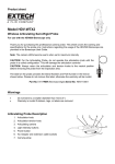
2. Valve User Interface
Regeneration Indicator
Service Manual
Flow Rate Indicator
Parameter Display
Time Display
Cycle Nº
Next Button (
Regeneration Button ( R )
Up Button (
)
Down Button (
)
)
Mixing Valve
Drain Line
Brine Line
Outlet
Inlet
3
Spectrum
TM
3. Installation Instructions
Service Manual
3.1. System Pressure
•
•
•
A minimum pressure of 2 bar is necessary to ensure normal operation of the control valve.
The maximum operating pressure must not exceed 8 bar in order to prevent damage during installation and
service. (If necessary, a pressure regulator should be installed upstream of the system.)
If the supply line is closed, take care to prevent any negative pressure in the system. It is recommended to put the
valve in the bypass position or place pressure release valves on the inlet and outlet of the system.
WARNING!
WATER STORAGE TANKS AND VESSELS ARE EXTREMELY SENSITIVE TO NEGATIVE PRESSURE AND CAN BE
DESTROYED DUE TO VACUMING EFFECTS.
3.2. Electrical Supply
•
•
•
•
If the system is provided with a low voltage transformer, make sure that the electrical supply cannot be interrupted
with a switch.
If the electrical cable or the transformer is damaged, it must be replaced by qualified personnel.
Make sure that the electrical line is protected by suitable electromagnetic protection.
If the system is battery operated, pull and remove the red tab to connect the battery.
3.3. Water Supply
•
•
The existing water supply should be clean and neat, free from limescale and iron. It should comply with current
regulations. (Any necessary changes should be made prior to installation).
It is recommended to install a pre-filter upstream of the system.
3.4. System Bypass
•
It is strongly recommended to provide a bypass on installation if the valve does not include one.
3.5. Temperature
•
•
•
The maximum temperature of the feed water should not exceed 42°C.
Any brazing or welding operations should be made prior to installation, as heat from the welding process may
damage plastic components of the system.
Ambient temperature should not decrease below 1°C. Freezing can break or severely damage parts of the system.
3.6. Installation of the System
•
The area where the equipment will be placed must be flat, even and able to support the weight of the system.
NOTICE:
CONNECTION OF THE EQUIPMENT TO THE WATER SUPPLY SHOULD BE CARRIED OUT BY QUALIFIED PERSONNEL.
4
Spectrum
TM
4. Valve Inital Set-Up
Service Manual
4.1. Adjust the Time of Day
•
Push the “UP /
” and “DOWN /
” buttons to set the correct time.
NB. The display of a valve using a low voltage transformer will blink during power failure. This blinking will end once
the time has been restored.
4.2. Displaying the Remaining Volume of Water to be Treated (Metered System Only)
•
Push the “NEXT /
” button to switch between the time of day and the remaining volume display.
4.3. Initiate a Regeneration
•
•
Push the “regeneration / R” button for one second to initiate regeneration (the system will regenerate immediately for
a valve in “immediate regeneration mode” or at the next pre-set time for a valve in “delayed regeneration mode”).
Push the “REGENERATION / R” button for 5 seconds to initiate regeneration immediately for a valve that is
programmed in “chronometric” or “volumetric” mode.
4.4. In Service
•
The display will show the time of day during normal operation and will turn off after 3 minutes to conserve battery
life for battery operated models. The remaining volume of water to be treated can be displayed by pushing the
“NEXT ” button.
5
Spectrum
TM
5. System Initial Set-Up
Service Manual
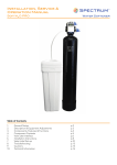
5.1.
The distribution tube should be cut 13mm (± 3 mm) above the top of tank. The open end of the tube
should be bevelled to remove sharp edges that may damage the O-ring seal.
5.2.
Put a small quantity of silicone lubricant on the bevelled end of the tube to aid installation. (Other
lubricants can be used but these should be checked to ensure that they are compatible and comply
with food and water regulations).
5.3.
All components of the system should be assembled by hand (never use extra tools that can apply
excessive force on components). Put a small quantity of silicone lubricant on the top O-ring to aid
installation. (Do not apply grease on the main thread as this can cause over-tightening and create
excessive stress on plastic components).
5.4.
Ensure that the pressure vessel is upright and stable.
5.5.
Connect the system to the water supply.
5.6.
Connect the drain hose barb on top of the valve to the drain with a plastic tube (Ø 13 mm). A screw
clamp can be used to secure the assembly of the tube on the valve. The clamp should not be over
tightened to prevent any excessive stress on the plastic hose.
5.7.
Connect the brine tube to the valve using ⅜" tubing. The quick-connect fittings in the valve and brine
line require no additional tools.
5.8.
Ensure that the system is in bypass position. Open the feed water tap slowly and allow the water to
flow to the drain to clear any debris. When the water appears clear, turn off the tap.
5.9.
Move the system into service position and open the inlet water tap. Once the air has been purged from
the system and water is flowing clearly, close the inlet tap.
5.10.
•
Power Source: 2 x LR20 Batteries
Remove the front cover of the valve using a screwdriver. Install two LR20 batteries and connect
the battery power lead to the electronic board. If necessary the electronic controller will return the
valve to service position. Replace the front cover and secure by tightening the screw.
•
Power Source: 230V mains
Plug the transformer to the main power line. If necessary the electronic controller will return the
valve to the service position.
5.11.
Adjust the time of day with the
&
push buttons. The control valve is now in operation.
5.12.
Fill the brine tank with approximately 3cm of fresh water. The air check valve should be completely
immersed.
5.13.
Initiate regeneration and advance the valve to the brine draw cycle. Let the system continue through
the remaining cycles.
5.14.
Add salt into the brine tank to the maximum level. The system is now in operation.
6
Spectrum
TM
6. Troubleshooting
Problem
Symptom
1.Used or defective batteries
2.Disrupted electric supply
3.Damaged meter cable
A. The system will not regenerate
4.Water meter turbine blocked
5.Defective drive motor
6.Defective electronic board
Service Manual
Resolution
1. Replace old batteries
2. Recover the power supply
3. Verify the connection & inspect cable
4. Clean or replace the turbine
5. Replace the drive motor
6. Replace the electronic board
B. There is hard water coming
from the outlet
1.No salt in the brine tank
2.System in bypass position
3.Internal leak in valve
4.Dirty breech
5.Low brine tank refill
6.See symptoms in “A”
1. Refill the brine tank
2. Return the system to service position
3. Change the internal seals
4. Clean the breech
5. Change the two breech seals
6. See resolution in “A”
C. Decrease in pressure and flow
1. Clean or replace the supply line to
the system
1.Iron build up in the water supply
2. Clean the valve and the resin bed.
2.Iron build up in the system
3. Increase backwash time to prevent
3.Levels of iron too high in the feed water
fouling. Specifically install an additional filter to remove iron.
D. High levels of brine present in 1.Clogged drain line
the brine tank
2.Defective cycle time
1. Check and clean the drain line
2. Adjust the cycle times
1.Clogged injectors
2.Clogged drain line
E. The outlet water tastes “salty” 3.Clogged brine valve
4.Defective cycle time
5.Damaged drain flow control
1. Clean the injectors
2. Check the drain line and flow control
3. Clean or replace the piston assembly
4. Adjust the cycle time
5. Change the flow control
F. There is a constant leak during
normal operation
G. Valve regenerates continuously
1. Change the seals
1.Defective seal
2. Change the piston
2.Defective piston
3. Change the piston and the seals and
3.Control valve blocked in regeneration
spacers
4.Defective power head
4. Change the power head
1.Defective power head
1. Change the power head
7
Spectrum
TM
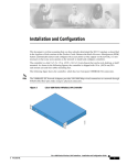
7. Spare Parts
Service Manual
Breech Seals
Breech N°1
Breech Cover
Piston Assembly
Main Seals
Brine Housing
Mixing Device
Brining Seals
Piston Flange
8
Spectrum
TM
8. Technical Information
Maximum Operating Temperature (ºC)
42
Minimum Operating Temperature (ºC)
1
Maximum Operating Pressure (bar)
8
Minimum Operating Pressure (bar)
2
Hydrostatic Test Pressure (bar)
20
Test Pressure (bar)
1-14 bar (250000 cycles)
1-24 bar (70000 cycles)
Max Flow Rate (m3/hr)
4.5
Inlet / Outlet (")
¾
Drain Line (")
½
Brine Line (")
⅜
Distribution Tube Diameter (mm)
27
Distribution Tube Length (mm)
13mm above the top of the tank (± 3mm)
Power Requirements
230 V
Net Weight (kg)
2.35
Service Manual
The WTVP-S512 complies with the following European directives:
• N° 89/339EEC Electromagnetic Compatibility
• N° 73/23/EEC Low Voltage
• N° 2002/95/CE RoHS
• ACS 13 ACC LY 805
9