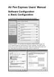
1
(Australia) Pty Ltd
TPMS-201-D-V2 Tyre Pressure
Monitoring System (TPMS)
User and Installation
Guide
Product features and installation instructions
for the TPMS-201-D-V2 tyre pressure and
temperature monitoring system
Document Number: 912-9001 Rev H – July 2014
Pty Ltd
TPMS-201-D-V2 User and installation guide
Document 912-9001 Rev H – July 2014
TABLE OF CONTENTS
1.
TPMS-201-D PRODUCT OVERVIEW.................................................................................. 1
2.
PRODUCT FEATURES........................................................................................................... 3
2.1
2.2
3.
INSTALLATION ...................................................................................................................... 5
3.1
3.2
3.3
3.4
3.5
4.
FEATURES SUMMARY .......................................................................................................... 3
THEORY OF OPERATION ...................................................................................................... 4
INSTALLING DISPLAY UNIT.................................................................................................. 5
3.1.1 Mounting location ................................................................................................. 5
3.1.2 +12V power source determination ....................................................................... 5
3.1.2.1 Cigarette lighter power option: ............................................................. 5
3.1.2.2 Hard wired power option: ..................................................................... 6
3.1.3 RF Antenna............................................................................................................ 6
3.1.4 Fixing display module into place.......................................................................... 7
3.1.5 Reconnect vehicle battery..................................................................................... 8
INSTALLING SENSOR/TRANSMITTER MODULES .................................................................... 8
3.2.1 Identify the ID-keys............................................................................................... 8
3.2.2 Sensor Disassembly............................................................................................. 10
3.2.3 Loosen Electronic module................................................................................... 10
3.2.4 Fix Sensor............................................................................................................ 10
3.2.5 Adjust head angle ................................................................................................ 10
3.2.6 Torque valve stem ............................................................................................... 11
3.2.7 Mount tyre ........................................................................................................... 11
3.2.7.1 Lubricate............................................................................................. 11
3.2.7.2 Position tyre ........................................................................................ 12
3.2.7.3 Position upper bead............................................................................. 12
3.2.7.4 Finish fitting tyre................................................................................. 13
SETTING THE BASELINE PRESSURE..................................................................................... 13
3.3.1 Step 1 ................................................................................................................... 13
3.3.2 Step 2 ................................................................................................................... 13
TURNING ON THE SENSOR/TRANSMITTERS ........................................................................ 14
CHECKING THAT THE SYSTEM WORKS ............................................................................... 14
TYRE REMOVAL.................................................................................................................. 15
4.1
4.2
BREAKING UPPER AND LOWER BEAD ................................................................................. 15
UPPER AND LOWER BEAD DEMOUNT .................................................................................. 15
Page II
Copyright 2009 @ll rights reserved
This document is not to be reproduced or copied in ^ny w^y unless the express permission in writing h^s been obt^ined
from In^wise Pty Ltd (@ustr^li^)
Pty Ltd
TPMS-201-D-V2 User and installation guide
Document 912-9001 Rev H – July 2014
5.
OPERATING PROCEDURE ................................................................................................ 16
5.1
5.2
5.3
5.4
5.5
5.6
GENERAL .......................................................................................................................... 16
TURNING ON LCD BACKLIGHT ......................................................................................... 16
DISPLAYING TYRE TEMPERATURE..................................................................................... 17
DISPLAYING SENSOR KEY ID............................................................................................ 17
DISPLAYING BASE PRESSURE ........................................................................................... 17
SETTING BASE PRESSURE OR CHANGING PRESSURES FOR DIFFERING OFF/ON ROAD
CONDITIONS ...................................................................................................................... 18
5.7 ROTATING TYRES ............................................................................................................. 18
5.8 DISABLING MONITORING OF SPECIFIC WHEELS .................................................................. 19
5.9 REPLACING SENSORS ........................................................................................................ 20
5.10 SPARE TYRES .................................................................................................................... 20
6.
DISPLAYS AND WARNINGS .............................................................................................. 21
7.
TROUBLE SHOOTING ........................................................................................................ 23
8.
FREQUENTLY ASKED QUESTIONS ................................................................................ 24
9.
WARRANTY AND SUPPORT.............................................................................................. 27
10.
TECHNICAL SPECIFICATIONS........................................................................................ 28
........................................................................ 28
11.
SAFETY WARNING.............................................................................................................. 29
12.
REPLACING VALVE CAPS ................................................................................................ 29
13.
FCC COMPLIANCE ............................................................................................................. 29
14.
DISCLAIMER......................................................................................................................... 29
Page III
Copyright 2009 @ll rights reserved
This document is not to be reproduced or copied in ^ny w^y unless the express permission in writing h^s been obt^ined
from In^wise Pty Ltd (@ustr^li^)
Pty Ltd
TPMS-201-D-V2 User and installation guide
Document 912-9001 Rev H - July 2014
1. TPMS-201-D Product overview
Thank you for choosing an Inawise Tyre Monitoring product. Not only will this product make your
vehicle safer, but you are also helping the environment by using less fuel and increasing the life of
your tyres. Such is the impact that this type of device can have, that tyre monitoring systems have
been made mandatory in the USA as of September 2007 for all new vehicles manufactured and
brought into the USA. Europe has since followed this lead mandating TPMS in 2012. It is speculated
that many if not most other countries will follow this lead.
The TPMS-201-D is a realtime Tyre Pressure (and temperature) Monitoring System (TPMS).
“Realtime” means the actual temperature and pressure at that moment in time. The system is
designed to constantly monitor vehicle tyre pressure and temperature whenever the display unit is
powered up.
The kit consists of a display unit, 4 sensors, a
power cord, a cigarette lighter adaptor and an
integrated dual wire antenna.
Since the display unit consumes very little
power, it is recommended that the display unit
be hardwired to the vehicle’s 12V electrical
system. The 12V supply should be live
irrespective of the position of the ignition key
switch. This will enable the TPMS-201-D to
monitor the tyres not only when the vehicle is
being driven, but also when it is parked.
The TPMS-201-D is
designed to monitor
4 wheels and hence is designed for 4 wheel vehicles only, including
4WDs. The kit is supplied with 4 sensor assemblies which need to be
fitted to each wheel of the vehicle. Each of the sensors consists of a
valve stem, incorporating the new tyre valve and electronic assembly
which is encapsulated within the plastic/silicon housing.
The actual electronics within the sensor consist of a low power 433.92 MHz RF transmitter, a
microprocessor with embedded temperature and pressure transducers, a motion detector and a
lithium battery as a power source. None of the electronic components, including the lithium battery
are serviceable or replaceable. In the event of a failure the whole valve sensor assembly can be
replaced.
The sensors need to be fitted in place of the existing tyre valves. To do this the tyre needs to be
removed from the rim, the sensor fitted and then the tyre re-fitted. Normally this work is carried out
most efficiently by a specialised tyre fitter or tyre retail outlet. Only rims with a tyre valve
Page 1
Copyright 2009 @ll rights reserved
This document is not to be reproduced or copied in ^ny w^y unless the express permission in writing h^s been obt^ined
from In^wise Pty Ltd (@ustr^li^)
Pty Ltd
TPMS-201-D-V2 User and installation guide
Document 912-9001 Rev H - July 2014
mounting hole of 11.3 mm are supported. This is the standard size for most OEM and after market
rims.
The battery life of the sensors has been designed to last for 4-7 years (typical) or 250,000 km of
driving. The concept is that if a set of sensors is fitted to a vehicle at the time that a new set of tyres
are fitted, the sensors will outlast the life of the tyres. As that set of tyres is replaced, it can then be
determined whether the sensors should be replaced or whether they can be utilised for another tyre
cycle.
The valve stem section of the sensor assembly is manufactured from a high grade aluminium with a
propriety finish to prevent corrosion. Aluminium is utilised to ensure the sensor assembly weight is
kept to a minimum, while at the same time providing mechanical strength. This low weight is
essential to ensure that wheel balancing can be easily achieved. Under certain environmental
conditions electrolysis can occur if a steel valve cap is fitted to the valve stem. This electrolysis will
cause the valve stem to corrode. As a result it is recommended that only the supplied plastic or an
aftermarket aluminium valve cap be used.
The encapsulated electronics will ensure reliable operation even in dirty, muddy and humid
environments. In addition the encapsulation will also ensure the sensor can withstand heavy
vibration from rough dirt roads or even motor racing applications. As all the electronics are
environmentally and mechanically insulated and isolated, including the lithium battery, the unit is
not serviceable in any way, nor can the battery by replaced.
Additional sensors can be purchased and fitted to spare tyres, however only 4 wheels can be
monitored at any one time. Tyres can be easily rotated along with spare tyres due to Inawise’s
patented sensor ID technology. (See section 5.7 on Tyre Rotation)
Page 2
Copyright 2009 @ll rights reserved
This document is not to be reproduced or copied in ^ny w^y unless the express permission in writing h^s been obt^ined
from In^wise Pty Ltd (@ustr^li^)
Pty Ltd
TPMS-201-D-V2 User and installation guide
Document 912-9001 Rev H - July 2014
2. Product Features
2.1 Features summary
Display and monitor tyre pressure and temperature of 4 wheels simultaneously
Unique patented sensor ID technology
Simple “set and forget” operation, or can be used as a performance driving aid informing
the driver of real time tyre pressures and temperatures
Reduces the risk of catastrophic tyre blowouts due to low pressure or over temperature
Programmable reference base tyre pressure for each individual tyre
Support for different reference base pressure for each wheel
Audible and visual alert on over pressure
Audible and visual alert on under pressure
Audible and visual alert on fast leak detection (over 3.6 psi in a 16 second period)
Audible and visual alert on over temperature
Display unit powered from vehicle 12V supply, no need for batteries
LCD display with white LED backlight.
Front panel “function” button to switch between pressure and temperature display.
Rear On/Off power switch
Compatible with vehicles which have tinted windows containing metallised film
Intelligent power saving technology enables battery life of sensors to last up to 4-7 years or
250,000 km.
Sensor electronics and tyre valve all in one assembly
Electronic module located inside rim and protected from external damage
Sensor electronics encapsulated in silicon, creating environmental isolation, ensuring long
life and reliability in harsh environments.
Aluminium valve stem with proprietary protective coating to guard against corrosion in
harsh environments.
Virtually immediate driver alert when problem is detected
1 year warranty.
Low power consumption.
CE/FCC/E-Mark standards certification
Page 3
Copyright 2009 @ll rights reserved
This document is not to be reproduced or copied in ^ny w^y unless the express permission in writing h^s been obt^ined
from In^wise Pty Ltd (@ustr^li^)
Pty Ltd
TPMS-201-D-V2 User and installation guide
Document 912-9001 Rev H - July 2014
2.2 Theory of operation
The Sensor/Transmitter modules are mounted inside each wheel rim and are held in position by a
special aluminium stem tyre valve, which replaces the existing tyre valve. The sensors monitor the
tyre pressure and transmit this information at predetermined intervals via RF (Radio Frequency) to
the display module. These transmissions occur every few seconds when the vehicle is moving and
only every few minutes when the vehicle is stationary, in order to conserve the life of the lithium
battery located within each sensor.
Whenever the display is powered up it receives this information via an RF signal. The display
module’s first step is to ascertain whether the information is from a valid sensor, and if so which
wheel it relates to. This is done via the ID-Key technology. Each sensor has a unique ID. No two
sensors have the same ID. Each sensor’s ID is associated with an “ID-Key” which is a device which
looks like a button and plugs into the side of the display module. This ensures only information from
the correct sensors is read and displayed.
The display unit, on qualifying the identity of the data from the RF signal, then evaluates the data to
ensure it is within valid parameters. The new data is displayed onto the LCD screen and if a problem
is detected the data is highlighted and an alarm is sounded.
Since tyre pressure can vary significantly due to variation in tyre temperature, it is the actual sensor
which carries out the determination of whether air is leaking from the tyre, while the display unit
determines whether the pressure is within defined limits. The microprocessors within the sensors
cross reference changes in tyre pressure with changes in tyre temperature. An algorithm determines
whether the change in tyre pressure is due to a leak or simply due to a change in tyre temperature.
The sensor modules incorporate a motion detector to determine if the vehicle is parked or moving.
When the vehicle is parked the sensors conserve power by monitoring the tyre and transmitting data
to the display at two-minute intervals provided the tyre is within a normal pressure range. If the
vehicle is moving, the sensor will check pressure and temperature every 2 seconds. When there is
no leakage the sensor will transmit data to the display at 30-second intervals. When there is a tyre
leak, the sensor will immediately send the signals to the display which will instantly sound an alarm
and indicate the problem.
Page 4
Copyright 2009 @ll rights reserved
This document is not to be reproduced or copied in ^ny w^y unless the express permission in writing h^s been obt^ined
from In^wise Pty Ltd (@ustr^li^)
Pty Ltd
TPMS-201-D-V2 User and installation guide
Document 912-9001 Rev H - July 2014
3. Installation
Installation instructions for the TPMS-201-D
Premise: The Display unit does not require professional installation, however it is recommended
that the Display unit be “hard wired” to the vehicles electrical systems (rather than the 12V
Cigarette lighter output), as such a general aptitude with the ability to identify, cut, strip and join
wires is required.
The sensors need to be installed in each wheel in place of the standard existing tyre valve stem.
While this can be done by a non professional, it is time consuming and hard work without the
correct equipment. In addition, on completion the wheels need to be dynamically balanced which
can only be done with the appropriate tyre balancing equipment. Any tyre shop or corner service
station will be able to provide this service cheaply and efficiently.
3.1 Installing Display unit
3.1.1 Mounting location
Identify a suitable location to mount the
display unit. The unit should be located
in a position where the display can be
easily read while driving, but not in a
location where it obscures driver view.
Within a compartment in the console
(right), or on top of the dash are all
suitable locations.
Once a location has been identified
consider where the power cables will be
run. It may be necessary to slightly move
the mounting location or find a new
location so that the power cables can be
hidden or at least run where they cannot
be interfered with, or be accidently
pulled by the driver or any of the
passengers.
3.1.2 +12V power source determination
At this stage you now need to determine if you intend to hard wire the 12V power
(recommended), or use the 12V Cigarette lighter adaptor. If you are going to use the Cigarette
lighter go to Step 3.1.2.1; if you are going to hard wire the 12V supply, go to Step 3.1.2.2
3.1.2.1 Cigarette lighter power option:
With the ignition turned off, plug the cigarette adaptor cable into the power cable
connector running to the display. Locate the display module in the approximate location
Page 5
Copyright 2009 @ll rights reserved
This document is not to be reproduced or copied in ^ny w^y unless the express permission in writing h^s been obt^ined
from In^wise Pty Ltd (@ustr^li^)
Pty Ltd
TPMS-201-D-V2 User and installation guide
Document 912-9001 Rev H - July 2014
you intend to mount it (but do not mount it as yet). Run the power cable from the display
unit to the cigarette lighter outlet so that it is supported by the surrounding trims or
console and if possible hidden out of sight. If possible run the cable behind or under the
dash, so as to hide it wherever possible. Plug in the cigarette lighter connector to the
cigarette lighter output and ensure the cable is long enough and not stretched at any point.
Now proceed to Step 3.1.3
3.1.2.2 Hard wired power option:
Locate the closest and most convenient location where you can tap into the +12V supply.
Remember the supply must be permanently on even when the ignition is turned off.
Normally the vehicles stereo system uses such a supply for the clock function. Next
disconnect the vehicle’s primary lead acid battery by removing the negative (Black)
terminal from the battery.
NOTE! Many modern vehicles have stereo systems equipped with an anti theft security
feature. This feature requires a security code to be entered into the stereo system before
it can be powered up once the 12V supply is removed. If you have such a system, ensure
you have access to this security code.
Locate the display module in the approximate location you intend to mount it (but do not
mount it as yet). Next plug the hard wired power connector cable into the socket on the
power cable for the display unit and run the cable neatly, and if possible out of view, to
the location where you have identified as the most convenient location to tap into the
+12V supply. Join the red wire (+) you have just run to the 12V source. Then join the
black or blue (-) wire to any ground connection point. The wires can be joined using any
conventional technique such as “wire joining crimp connectors” or by cutting, stripping
and soldering the wires together. On completion ensure the wires are not exposed or
shorting. If they are exposed, use isolation tape to cover the joint. Finally use the cable
ties supplied to hold the cable firmly in place. Ensure the cable is well supported and does
not hang in any area where it can be pulled on, or caught onto anything. Now go to Step
3.1.3
3.1.3 RF Antenna
The wire antenna is used to receive the RF signal from the four individual sensors/transmitter
modules fitted to each wheel rim. The TPMS-201-D is equipped with two long coaxial wire
antennas hard wired into the display module. The wire antennas consist of black coaxial cable
with a clear wire section at the end, approximate 100 mm long. This clear wire section is the
actual reception part of the wire antenna. These antennas need to be positioned so that a
reliable level of signal reception is obtained.
The antenna can be installed internally within the passenger compartment, or run through the
firewall and located externally beneath the vehicle. When installing internally, run the two wire
antennas in opposite directions across the dash (or preferably hidden under the dash) and
around the vehicle. Wherever possible hide the wires behind trimming. Try to ensure the last
100 mm end of the wire antennas are left “Free standing” and away from other wires and metal
objects. This is the primary point where the RF signal is picked up.
Page 6
Copyright 2009 @ll rights reserved
This document is not to be reproduced or copied in ^ny w^y unless the express permission in writing h^s been obt^ined
from In^wise Pty Ltd (@ustr^li^)
Pty Ltd
TPMS-201-D-V2 User and installation guide
Document 912-9001 Rev H - July 2014
In some applications the wire antennas will need to be located externally in order to obtain
satisfactory RF reception. To do this run the antenna wires through the firewall, into the engine
compartment, and then run down to the bottom of the chassis. Ensure the last 100mm of the
antenna wires (Clear wire section) are at least 25 mm away from any metal object such as the
chassis or vehicle panel. Here the wire antenna will be located closest and in direct “line of
site” to the RF transmitters mounted within the rims and hence will give the best reception and
long term performance. Use cable ties to secure the antenna wires and ensure they are kept
away from the exhaust or any other object which may get hot.
NOTE: While many installations will work fine with the antenna installed inside the passenger
compartment of the vehicle, occasional reception problems may be encountered as the RF
power output of the sensors reduces, as the batteries age. As such we recommend the antennas
be mounted EXTERNALLY.
When there is no leakage the sensor will transmit data to the display at 30-second intervals.
When there is a tyre leak, the sensor will immediately send the signals to the display which will
instantly sound an alarm and indicate the problem.
3.1.4 Fixing display module into place
Fix the display module into place using the double sided adhesive supplied. Ensure both
surfaces are clean and if necessary clean with methylated spirits.
Page 7
Copyright 2009 @ll rights reserved
This document is not to be reproduced or copied in ^ny w^y unless the express permission in writing h^s been obt^ined
from In^wise Pty Ltd (@ustr^li^)
Pty Ltd
TPMS-201-D-V2 User and installation guide
Document 912-9001 Rev H - July 2014
3.1.5 Reconnect vehicle battery
The vehicle battery can now be reconnected. The display module will power up once the rear
On/Off switch is switched to ON. As the display module powers up, the unit will beep and all of
the displays will read “000” as the sensors are yet to be fitted to the wheels.
WARNING! Plugging or Un-Plugging the ID-KEYS with
the display still turned “on” can irreparably damage the
memory within the ID-KEY requiring the ID-KEY and
sensor to be replaced.
3.2 Installing Sensor/Transmitter modules
The sensor/transmitters need to be installed to each of the 4 wheels. The modules include a new tyre
valve, so the existing tyre valve needs to be removed and discarded. In order for the sensors to be
installed, the wheels need to be removed from the vehicle and the tyres then removed from the rims.
(NOTE: With some tyre/rim combinations, it is possible to fit the sensor by breaking the tyre bead
and pressing the tyre wall away from the location of the valve hole on the rim, in order to create
working clearance suitable to install the sensor module. This method reduces the time required, as
the tyre does not have to be completely removed from the rim. Care must be taken to ensure the
tyre wall does not unexpectedly spring back into place and cause human injury.)
3.2.1 Identify the ID-keys
Each sensor is labelled with a letter “A”, “B”, “C” or “D” on its valve stem. The letters
correlate to the same letters on the identifier ID keys plugged into the side of the display
module. The sensors and ID keys also have codes to identify and pair them. Each pair is unique
and cannot be interchanged.
This ‘C’ ID key can only be used with this sensor – the codes on each must be the same.
By default the Left Side front tyre is allocated Sensor “A”. The Right Front is sensor “B”. The
Left Back is sensor “C” and the Right Back is sensor “D”. These positions relate to the
representation of the wheel on the LCD display. The ID-Keys can be unplugged from the
display module and relocated as required. In order to unplug the ID-Keys the “release” button,
located on the back of the unit, must first be depressed. There are two release buttons located
Page 8
Copyright 2009 @ll rights reserved
This document is not to be reproduced or copied in ^ny w^y unless the express permission in writing h^s been obt^ined
from In^wise Pty Ltd (@ustr^li^)
Pty Ltd
TPMS-201-D-V2 User and installation guide
Document 912-9001 Rev H - July 2014
on either side of the back panel. (See diagram on page 19.) This then allows the ID-Key to be
unplugged. It is recommended that the sensors be fitted in the default order to avoid the IDKeys requiring rotation during this initial installation.
Once the ID codes for the sensor/transmitters have been identified they can be fitted to the
rims.
The sensor is made up of a number of parts identified below.
Page 9
Copyright 2009 @ll rights reserved
This document is not to be reproduced or copied in ^ny w^y unless the express permission in writing h^s been obt^ined
from In^wise Pty Ltd (@ustr^li^)
Pty Ltd
TPMS-201-D-V2 User and installation guide
Document 912-9001 Rev H - July 2014
3.2.2 Sensor Disassembly
Remove the Valve Cap and the Retaining
Nut from the valve stem. The Retaining Nut
has a plastic washer pressed into its seat.
3.2.3 Loosen Electronic module
Loosen the self-locking screw to allow the Electronics module to be adjusted to fit the rim.
Clean the rim around the valve hole both on the inside and out. Insert the valve stem through
the valve hole, from the inside of the rim.
3.2.4 Fix Sensor
The
valve
stem fixing nut
incorporates a self retained plastic
washer. Fit the nut to the valve stem
and tighten only by hand, ensuring
the washer is in place on the nut.
3.2.5 Adjust head angle
Now adjust the angle of the electronics
module so it sits as close as possible to the
rim surface, preferably hard against it, then
tighten the Self locking screw to lock the
electronics module into that position.
Ensure the self-lock screw is in the correct
position (see below) to provide the largest
adjustable angle.
Page 10
Copyright 2009 @ll rights reserved
This document is not to be reproduced or copied in ^ny w^y unless the express permission in writing h^s been obt^ined
from In^wise Pty Ltd (@ustr^li^)
Pty Ltd
TPMS-201-D-V2 User and installation guide
Document 912-9001 Rev H - July 2014
3.2.6 Torque valve stem
Tighten the valve stem NUT with 3.5 to
4.6Nm (2.6 – 3.4 foot pounds) of torque.
(Note: Correct torque setting is critical.
Under tightening will cause air to leak. Over
tightening will cause the “valve stem air seal
rubber washer” to fail causing air to leak.
The nut can be tightened without the use of a
torque wrench. The correct torque is
reached when the “valve stem air seal
rubber washer” is compressed to 60-70% of
its original thickness, and is not seen to be
overly bulging).
3.2.7 Mount tyre
The tyre can now been mounted back onto the rim.
3.2.7.1 Lubricate
Apply lubricant to both the tyre bead and the rim.
Page 11
Copyright 2009 @ll rights reserved
This document is not to be reproduced or copied in ^ny w^y unless the express permission in writing h^s been obt^ined
from In^wise Pty Ltd (@ustr^li^)
Pty Ltd
TPMS-201-D-V2 User and installation guide
Document 912-9001 Rev H - July 2014
3.2.7.2 Position tyre
The lower bead must be mounted with the
mounting head of the changer located at 12
o’clock while the position of the tyre valve is at 7
o’clock. This is done to ensure the electronic
module will not be damaged.
3.2.7.3 Position upper bead
The upper bead must be mounted with the
mounting head of the tyre changer positioned at
12 o’clock and the valve at 5 o’clock
Page 12
Copyright 2009 @ll rights reserved
This document is not to be reproduced or copied in ^ny w^y unless the express permission in writing h^s been obt^ined
from In^wise Pty Ltd (@ustr^li^)
Pty Ltd
TPMS-201-D-V2 User and installation guide
Document 912-9001 Rev H - July 2014
3.2.7.4 Finish fitting tyre
The tyre can now be inflated to the vehicles recommended specified cold tyre pressures
and dynamically balanced.
Repeat procedure for all other wheels and then refit wheels to vehicle.
3.3 Setting the baseline pressure
The system is pre-set at the factory with a pressure range of 29-36 PSI and will warn you if your
tyres fall to 23 PSI or increase to 46 PSI. This range should be suitable for the majority of vehicles.
However, you can set your own level and most prefer to do so.
So, the final step is to set the baseline pressure for your vehicle if you do not want the factory
settings. The baseline pressure is the “Cold tyre pressure” specified on the vehicles tyre pressure
placard normally mounted in one of the vehicle door jams.
To set the baseline pressure:
3.3.1 Step 1
Set all your tyres to the cold tyre pressure specified by the vehicle manufacturer.
3.3.2 Step 2
Press the “SET” button on the back of the display unit and hold the button down for at least 6
seconds. The Display module will now wait for the sensors to transmit a pressure reading. It will
use the first reading it receives and record it as the new baseline pressure. Each wheel is
handled individually and each wheel will have a new baseline pressure, set according to the
current air pressure to which the tyre has been inflated.
Page 13
Copyright 2009 @ll rights reserved
This document is not to be reproduced or copied in ^ny w^y unless the express permission in writing h^s been obt^ined
from In^wise Pty Ltd (@ustr^li^)
Pty Ltd
TPMS-201-D-V2 User and installation guide
Document 912-9001 Rev H - July 2014
3.4 Turning on the Sensor/Transmitters
The sensor units are shipped in a powered down sleep mode to conserve battery life and ensure
maximum battery life once they are put into service.
The sensors are activated from the “power down shipping mode” by pressurising the sensor or
driving the vehicle with the sensors installed on the wheels at a speed of 25 kph or more for a few
minutes.
As the sensors come on-line the display will change from displaying “000” to displaying the data for
that wheel.
3.5 Checking that the system works
The system should now be up and fully functional. All four readings on the display should be
showing the correct tyre pressure for all four tyres. To check that you have the baseline pressure
you want, quickly press the SET key. If the display shows ‘AAA’ you have the default factory
setting. If the display shows numbers, along with ‘PSI’ the numbers will be the current baseline
pressure. Just repeat step 3.3 if they are incorrect.
By pressing the “function” button located at the front of the display the display should first turn on
the LCD backlight. A second press will cause the display to toggle from pressure display to
temperature.
“Function” Button
The LCD backlight will stay on for only a few seconds and then automatically turn off again to
preserve power.
Page 14
Copyright 2009 @ll rights reserved
This document is not to be reproduced or copied in ^ny w^y unless the express permission in writing h^s been obt^ined
from In^wise Pty Ltd (@ustr^li^)
Pty Ltd
TPMS-201-D-V2 User and installation guide
Document 912-9001 Rev H - July 2014
4. Tyre Removal
If the rim is already fitted with a sensor/transmitter module, a specific procedure is required to break
the bead and remove the old tyre from the rim, in order to avoid the sensor/transmitters being
damaged.
4.1 Breaking upper and lower bead
The upper and lower beads must be broken with the bead breaker
head located AT LEAST 90 deg of arc away from the tyre valve
sensor/transmitter module.
This will ensure the sensor/transmitter is not damaged as the bead
separates from the rim.
4.2 Upper and lower bead demount
With the demounting head located at a 12.00 o’clock position,
ensure the tyre valve sensor/transmitter module is located at 11.00
o’clock. This will ensure that the sensor/transmitter will not be
damaged by the head. In addition it is important that the sensors be
located on the opposite side to where the tyre bead is stretched into
the rim cavity.
Page 15
Copyright 2009 @ll rights reserved
This document is not to be reproduced or copied in ^ny w^y unless the express permission in writing h^s been obt^ined
from In^wise Pty Ltd (@ustr^li^)
Pty Ltd
TPMS-201-D-V2 User and installation guide
Document 912-9001 Rev H - July 2014
5. Operating Procedure
5.1 General
The typical operating mode of the TPMS-201-D is “set and forget”. The system will monitor the
tyres and in the event of a problem, will sound an alert, turn on the LCD backlight and highlight the
tyre with the problem.
In the event the TPMS issues an alert, as soon as it safe to do so, the driver should slow down, turn
on the hazard lights, pull over to a safe location, and investigate the problem.
During normal operating mode, the driver can at any time read the individual tyre pressures of all 4
tyres. The location of the pressure or temperature readings on the LCD display relates to the
physical location of the tyre.
While the vehicle is parked the sensors will measure and transmit the tyre pressure and temperature
to the display unit every 2 minutes. The display will always display the most recent reading.
Once the vehicle starts to move, the sensors measure the tyre pressure and temperature every 2
seconds and transmit this information every 30 seconds to the display module. In the event the
sensor detects a problem, the information is transmitted immediately, which will cause the display
module to display the problem and give out an audible alarm.
5.2 Turning on LCD Backlight
The LCD backlight can be turned on manually by pressing the function button on the front of the
display panel once.
The LCD will remain backlit for a pre-programmed period of time (around 12 seconds) and then
turn off again. The backlight cannot be manually turned off or be configured to permanently remain
on, or programmed to stay on longer.
“Function” Button
Page 16
Copyright 2009 @ll rights reserved
This document is not to be reproduced or copied in ^ny w^y unless the express permission in writing h^s been obt^ined
from In^wise Pty Ltd (@ustr^li^)
Pty Ltd
TPMS-201-D-V2 User and installation guide
Document 912-9001 Rev H - July 2014
5.3 Displaying Tyre Temperature
The function button on the display will toggle between tyre pressure and temperature. When the
backlight goes out, the screen will return to the pressure interface.
5.4 Displaying Sensor Key ID
In addition to the labels “A”, “B”, “C” and “D” each transmitter/sensor has a unique 8 digit
identifier. Pressing and holding down the “Function” button on the font of the display module for 8
seconds until you hear the ‘beep’ sound will cause the display to enter the ID-Key display mode.
The display will show the ID Key code in 4 consecutive screens: The first screen will show the first
two digits of the 8 digit ID for all 4 tyres; press the front button to see the next 2 digits, and so on..
The example above indicates the ID key for the left front wheel is 01012BA8.
If the display shows “---” it indicates that the ID-Key is not plugged in correctly for that tyre, or the
system is faulty.
To resume the normal working mode, hold the “Function” button on the front of the display down
for 8 seconds.
5.5 Displaying Base Pressure
The “Baseline” pressure is the reference pressure used by the system to determine the nominal
correct pressure of each individual tyre. Normally this “Baseline” pressure should be set to the
manufacturer’s recommended “cold inflation pressure” as defined on the tyre plaque fitted to the
vehicle by the manufacture. Normally this plaque is located in one of the door jams or in the glove
box.
The system supports individual base pressure settings for each of the 4 tyres. Each tyre can be
individually configured for a specific base pressure. The system’s existing “Base” pressure setting
can be displayed by briefly pressing the “set” button on the back of the display.
Note: The system has a default setting range of 29-36 psi. It will alarm for a high pressure
warning of 46 psi and low pressure warning of 23 psi. When you set your own parameters, the
system converts to a baseline mode and gives warnings 30% above and 20% below the baseline
pressure.
Page 17
Copyright 2009 @ll rights reserved
This document is not to be reproduced or copied in ^ny w^y unless the express permission in writing h^s been obt^ined
from In^wise Pty Ltd (@ustr^li^)
Pty Ltd
TPMS-201-D-V2 User and installation guide
Document 912-9001 Rev H - July 2014
5.6 Setting Base Pressure or changing pressures for differing off/on road
conditions
The “Base” pressure (also referred to as BASELINE pressure) is programmable and can be set to a
different value for each tyre. Normally the wheels on the same axle would be set the same, however
front and back axles may vary. When going off road, tyre pressures will need to be reduced and
base pressures will therefore need to be reset.
Step 1: Inflate/deflate the tyres to the desired base pressure. This is best done when the tyres are
cold.
Step 2: Press and hold the “SET” button on the back of the display unit for 8 seconds until a beep is
heard.
Step 3: Wait for 5 minutes for the sensors to transmit the new reference data to the display unit, or
drive the vehicle at a speed greater than 25 kph. The display unit will now use the first reading
received from the sensors as the new base pressure.
(Note if this is the first time a new sensor is used, after installation it will need to be activated and
taken out of the “shipping sleep mode”. This is done by driving the vehicle for 5 minutes at a
speed greater then 25 kph.)
5.7 Rotating tyres
Rotating tyre requires the display to also be updated, so that the tyre readings are displayed in the
correct locations on the LCD.
Step 1: Physically rotate the wheels
on the vehicle as required.
Step 2: Turn the On/Off switch on the
back of the display module to the
“OFF” position.
Step 3: Rotate the “ID-Keys” in the
same sequence that you rotated the
tyres or go to each wheel and read the
letters “A”, “B”, “C” and “D” on each
of the valve stems and then position the
ID buttons in the correct position on
the side of the display module.
Step 4: Turn On/Off switch on the
back of the display unit to “On”
Page 18
Copyright 2009 @ll rights reserved
This document is not to be reproduced or copied in ^ny w^y unless the express permission in writing h^s been obt^ined
from In^wise Pty Ltd (@ustr^li^)
Pty Ltd
TPMS-201-D-V2 User and installation guide
Document 912-9001 Rev H - July 2014
NOTE: The ID-Keys are locked into position by a retaining mechanism inside the display unit. In
order to unplug the ID-Key, the release button must be depressed and held down while the ID-Key
is unplugged. There are two release buttons. One for the two left ID-Keys and one on the right for
the two right side ID-Keys.
WARNING! Plugging or Un-Plugging the ID-KEYS with the display still
turned on can irreparably damage the memory within the ID-KEY requiring the
ID-KEY and sensor to be replaced.
5.8 Disabling monitoring of specific wheels
This model TPMS is designed for use with 4 wheel vehicles but can be adapted for 1, 2, or 3 wheel
monitoring.
To do this, the display module has to be turned off and the ID-Keys relating to the sensors not
requiring monitoring need to be unplugged from the sides of the display module. Once the display
module is switched back on, only the sensors relating to the ID-Keys which are still plugged into the
display will be monitored.
If the ID-Keys are left plugged into the display, when not all 4 sensors are active, the display will
wait indefinitely for a pressure reading from all 4 sensors before any readings are displayed. In this
situation, the display can be forced to display whichever sensor readings it has received, by pressing
the “function” button on the front of the display.
If not all 4 sensors are present, and one or more present sensors detect a pressure or temperature
problem, the display will alert the driver to the problem and display the readings.
Page 19
Copyright 2009 @ll rights reserved
This document is not to be reproduced or copied in ^ny w^y unless the express permission in writing h^s been obt^ined
from In^wise Pty Ltd (@ustr^li^)
Pty Ltd
TPMS-201-D-V2 User and installation guide
Document 912-9001 Rev H - July 2014
5.9 Replacing Sensors
If a sensor fails it can be replaced. Replacement sensors are available from Inawise Pty Ltd.
Step 1: Remove the wheel from the vehicle and remove the tyre as described in Section 4 “Tyre
Removal”
Step 2: Remove the old sensor from the rim and fit the new sensor as described in Section 3.2
“Installing Sensor/Transmitter modules”
Step 3: Fit the tyre back onto the vehicle
Step 4: Turn On/Off switch on the back of the display unit to “Off”
Step 5: Replace the old “ID-Key” on the side of the display unit with the new one supplied with
the new sensor/transmitter.
Step 6: Turn the On/Off switch on the back of the display unit to “On”
Step 7: Drive the vehicle for 5 minutes at a speed greater than 25 kph to bring the new sensor out
of the shipping sleep mode.
(Note: If a sensor is replaced, the baseline pressure must be reset as per section 3.3 “Setting the
baseline pressure”. The baseline pressure is stored within the internal memory of the ID-Key)
5.10 Spare Tyres
Extra sensor/transmitter modules are available and can be fitted to spare tyres. The
sensor/transmitter modules are supplied with linked ID-Key buttons. When a spare tyre is fitted to
the vehicle, all that is needed is for the existing ID-Key to be unplugged from the display module
and the new ID-Key plugged into the display module. (See procedure for Rotating tyres on page
18.)
Page 20
Copyright 2009 @ll rights reserved
This document is not to be reproduced or copied in ^ny w^y unless the express permission in writing h^s been obt^ined
from In^wise Pty Ltd (@ustr^li^)
Pty Ltd
TPMS-201-D-V2 User and installation guide
Document 912-9001 Rev H - July 2014
6. Displays and Warnings
Low Pressure Warning
Warning Threshold
20% below Baseline Pressure
OR
Alerts
1)
Audible “beep”
2)
Display Backlight turns ON
3)
Problem indicator ICON is displayed
4)
Border around low reading is removed
Default factory setting: 23 psi
High Pressure Warning
Warning Threshold
Alerts
1)
Audible “beep”
2)
Display Backlight turns ON
3)
Problem indicator ICON is displayed
4)
Border around high reading is
removed
30% above Baseline Pressure
OR
Default factory setting: 46 psi
Page 21
Copyright 2009 @ll rights reserved
This document is not to be reproduced or copied in ^ny w^y unless the express permission in writing h^s been obt^ined
from In^wise Pty Ltd (@ustr^li^)
Pty Ltd
TPMS-201-D-V2 User and installation guide
Document 912-9001 Rev H - July 2014
High Temperature Warning
Warning Threshold
Alerts
Temperature above 80° C
1) Audible “beep”
2) Display Backlight turns ON
3) Problem indicator ICON is displayed
4) Border around high reading is removed
Fast Leak Warning
Warning Threshold
Air leak of more then 3.6 psi within a 16
second period
Alerts
1) Audible “beep”
2) Display Backlight turns ON
3) Fast LEAKAGE ICON is displayed
4) Border around low reading is removed
None-receiving data/No ID Key Warning
Warning Threshold
Alerts
None-receiving Data warning within 20
minutes
1) Display - - -
No ID key is detected
1) Display - - -
2) Border is removed
2) Border remains
Page 22
Copyright 2009 @ll rights reserved
This document is not to be reproduced or copied in ^ny w^y unless the express permission in writing h^s been obt^ined
from In^wise Pty Ltd (@ustr^li^)
Pty Ltd
TPMS-201-D-V2 User and installation guide
Document 912-9001 Rev H - July 2014
7. Trouble shooting
Problem
"000" shows on the
display
Possible reasons
Initial setup of systems
requires sensors to be
activated from shipping sleep
mode
Poor signal reception
Solution
Drive vehicle at 25 kph or
more for 5 minutes
Relocate dual long wire
antenna.
Move display away from
metal object and/or wires
Rear On/Off switch is turned
to Off
Flick rear switch to “On”
position
12V power cable is not
properly connected
Check wiring
In-Line fuse is blown
Replace fuse.
ID module is not properly
connected with the display
Carry out ID-key Check.
(Section 5.4)
System Lock-up
Switch the rear Power
switch to "OFF" then "ON".
Receiver or transmitter failure
Contact your local dealer.
Display beeps when
tyre pressure is OK
Baseline pressure not set
correctly
Set Baseline pressure as per
section 5.6
Display beeps in the
morning during cold
weather
Tyres are under inflated
Re-inflate tyre to correct
pressure
Baseline pressure not set
correctly
Set Baseline pressure as per
section 5.6
Weak RF signal link or
external source jamming RF
signal
Relocate dual long wire
antenna.
System Lock-up
Switch the rear Power
switch to "OFF" then "ON".
Nothing is shown on
display
"---" is displayed even
when you drive faster
than 25 kph
Sometimes, but not
always, the display
shows blank pressure
or temperature
Data does not refresh
Back light does not
turn off
The display continues
to show
incomprehensible
codes
Page 23
Copyright 2009 @ll rights reserved
This document is not to be reproduced or copied in ^ny w^y unless the express permission in writing h^s been obt^ined
from In^wise Pty Ltd (@ustr^li^)
Pty Ltd
TPMS-201-D-V2 User and installation guide
Document 912-9001 Rev H - July 2014
8. Frequently asked questions
1.
How reliable is the Inawise TPMS?
The product is manufactured under stringent TS16949 quality system guidelines. The product won the
Gold award from “Nation Intellectual Property Rights Bureau” (china) and passed inspections from the
“National Passenger Car Quality Supervision and Inspection Centre”. The product also meets
international FCC standard from the USA and e-mark/CE from Europe.
2.
Will it affect the performance of my car?
No. The Inawise sensor/transmitter modules weigh less than 50 grams. It is one of the lightest
aftermarket sensor/transmitter modules available. The display is designed to consume low power. Only
if the vehicle is not used for periods exceeding one month, should you turn the display off via the On/Off
switch located at the back of the display module.
3.
Can I use TPMS with my Nitrogen inflated tyres?
Absolutely Yes! Nitrogen will make the pressure inside the tyre more stable and reduce tyre aging. It is
possible to compare the different characteristics between air and nitrogen with the Inawise TPMS. For
high performance applications, Nitrogen filled tyres with a TPMS fitted is the ultimate setup.
4.
Can I use Tyre sealant with TPMS?
Generally, NO you can’t. However as TPMS becomes more mainstream, there are some new sealant
compounds coming onto the market which are designed to work with TPMS sensors. Read the manual
for the tyre sealant carefully to confirm compatibility.
5.
Will Inawise TPMS operate well in extremely cold or hot conditions?
The sensor’s operating temperature range is between -40° C to +125° C, while the display can operate
between -20° C to +70° C. Even in Australia, these temperatures are unlikely to be exceeded, however
just to be safe, avoid exposing the display module to extreme temperature during extremely hot days.
6.
Is the Inawise TPMS compatible with the other electronic products?
Yes. It has been approved by the FCC and e-mark, CE certificate. It won’t interfere with other electronic
products in the vehicle.
7.
Can the Inawise TPMS prevent tyre blowouts?
Blowouts are most commonly caused by driving long distances on “over stressed” tyres. Over stress can
be caused by overloading, excessive speed, or under inflated tyres. Excessive continuous distortion of
the tyre’s sidewalls will cause temperature build-up. This temperature build-up can then cause
catastrophic tyre failure known as a “Blowout”. Since the Inawise TPMS can alert the driver to not only
low tyre pressure which is the primary cause of blowouts, but also to excessive heat which can be
caused by overloading or excessive speed for long periods of time, the Inawise TPMS can significantly
reduce the possibility of blowouts occurring by alerting the driver to these dangerous parameters.
8.
How can I get after sales service?
The product has a 1 year warranty (refer to warranty section) and lifetime service. We recommend you
contact your dealer first, otherwise contact us through our website at www.inawise.com
9.
When driving, the tyre pressure and temperature seem to be constantly changing from one
moment to the next. Is there a problem with the system?
No, the readings are the actual tyre pressures at that instant. Normally, the tyres on the drive axle will
operate at a higher temperature. While driving, the climate, load, braking and the road conditions are the
Page 24
Copyright 2009 @ll rights reserved
This document is not to be reproduced or copied in ^ny w^y unless the express permission in writing h^s been obt^ined
from In^wise Pty Ltd (@ustr^li^)
Pty Ltd
TPMS-201-D-V2 User and installation guide
Document 912-9001 Rev H - July 2014
main factors that affect the tyre pressure and temperature, so the figures will be constantly changing as
these conditions change. This is why we say that our TPMS will provide readings in real time.
10. Can I cancel the warning alert and then pull over to check the tyre problem?
No, the alerts will not stop until the tyre pressures and temperatures are corrected. We recommend that
once you hear the alert beeps, slow down and turn your hazard lights on. Pull over to the road side and
work out what the problem may be. In the event a problem cannot be detected and it is determined that
the TPMS is giving a faulty reading (which is very unlikely) the display unit can be turned off using the
rear on/off switch.
11. How long will the batteries in the transmitters last and can they be recharged?
The batteries are designed to last for 4-7 years depending on usage. This is sufficient to outlast the tyres
and in some cases the vehicle itself. The batteries are not rechargeable, because they need to be
encapsulated and environmentally sealed along with the electronic module. (Water resistance is a
standard OE requirement from GM/FORD/CHRYSLER)
12. Can I re-install the Inawise TPMS on a new vehicle after it has been removed from another
vehicle?
Yes, but we suggest you replace the valve core/cap/sealing grommet whenever you replace the tyres or
move the sensors onto another rim. These are available as a service kit.
13. Can this model be used on Heavy duty trucks or busses?
No. We have other models for Heavy duty truck and coach busses.
14. How often does the TPMS check my tyre pressure & temperatures?
When vehicle speed exceeds 25~30 kph, the system samples the tyre pressure & temperature every 4
seconds and refreshes the display within 20 seconds. If a problem is found the display is updated
immediately, with further updates every 4 seconds. When the car is stopped or travelling at low speed,
the system samples data at longer intervals in order to extend the sensor/transmitter battery life.
15. How long does it take to install the complete Inawise TPMS?
Approximately 45 minutes to 1 hour depending on the skill of the operator. A tyre shop can complete the
installation according to this “user and installation” guide. We recommend you go to a tyre shop as they
have all the tools to quickly remove the tyres from the rims and fit the sensor/transmitters.
16. Is it necessary to buy any specified TPMS tool to carry out tyre rotation or maintenance?
No, no special tools are required. All that is required is for the corresponding ID-Key module to be
repositioned on the display module after the tyre is relocated. Engineers from Siemens VDO have
praised our patented ID-Key Module technology, claiming it as the best solution to the tyre rotation
issues they have seen.
17. When a sensor fails, what can I do?
You can buy a new sensor with its matched ID-Key to replace the faulty one. You just need to install the
new sensor to the rim and then plug the new ID-Key in the side of the display. Simple!
18. Why is the pressure reading from the Inawise TPMS always different to a reading I get with
an external tyre pressure gauge?
Every measuring instrument has a defined tolerance. This tolerance defines the accuracy of the
instrument. In the case of tyre pressure measurement, if the instrument has a tolerance of +/-1.5 psi it
means that a reading of 10 psi translates to a true pressure of anything between 8.5 psi to 11.5 psi. So if
you take two different gauges both with a tolerance of +/-1.5 psi, one could read 8.5 psi and the other
Page 25
Copyright 2009 @ll rights reserved
This document is not to be reproduced or copied in ^ny w^y unless the express permission in writing h^s been obt^ined
from In^wise Pty Ltd (@ustr^li^)
Pty Ltd
TPMS-201-D-V2 User and installation guide
Document 912-9001 Rev H - July 2014
one 11.5 psi. Even though there is a difference of 3 psi between the two readings, both gauges are
working correctly and within specifications.
1) A high quality precision tyre pressure gauge will have an accuracy of +/-0.75 psi
2) A good quality calibrated digital inflation gauge will have an accuracy of around +/-1.5 psi
The sensors used by Inawise are manufactured by GE (General Electric) and are considered high
accuracy, with a tolerance of +/-0.75 psi. It is most likely that the reading given by the Inawise TPMS
will be more accurate than any other reading you take.
19. Can I change the pressure and temperature unit?
No. The units are pre-set and are model specific. This model can only display units in PSI and ºC.
20. Can the Inawise TPMS be used for racing and motor sport applications?
Yes. The units can be used for racing however the over temperature warning will sound when the tyre (or
the air inside the tyre) reaches 80ºC. Normally even under racing conditions tyres do not run this hot,
making the unit a great tuning and performance tool for motor racing. Heavy braking may cause the heat
from the brakes to transfer over to the tyres causing the temperature to rise and exceed 80º; however a
high temperature warning may be a benefit even in this situation. The sensors are only 35 g so they will
not affect tyre balance and are also designed for their ruggedness, so they will not have trouble with the
high speed or the vibration.
Note: The beeper within the display can be easily heard in any passenger vehicle however it will not
be audible in a race vehicle or when a crash helmet is worn.
21. What makes this model suitable for 4WD applications?
4WD’s often require the tyre pressures to be adjusted to suit the terrain. A 4WD tyre monitor not only
needs to be rugged and reliable, but also needs to allow for constant tyre pressure adjustments. It needs
to be able to work at low pressures down to 8 psi and as high as 80+psi. In addition it needs to be able
to support different tyres at different pressures. Most importantly it must be quick and easy to adjust
when the tyre pressures are changed. This Inawise model can do all this and so is perfectly suited for
4WD applications.
When tyre pressures are adjusted to compensate for different terrains, all that is required is for the
“SET” button on the back of the display to be pressed. This tells the display to read all the individual
tyre pressures and record the current pressure it reads as the correct pressure. We refer to this pressure
as the “baseline” pressure. Once recoded, the system will give an alarm if the pressure inside the tyre
goes down by 20% or up by 30% from this recorded baseline. Each tyre is handled individually and has
its own baseline pressure recorded. The value is actually recoded within the memory of the ID-KEY,
hence when the tyre is rotated its baseline setting is maintained.
Ideally setting the baseline pressure should be done when the tyres are at a standing still cold
temperature. However this is often not possible, especially when 4WDing. If the baseline is set when the
tyre is hot, you may find that a low pressure warning is sounded when the tyre cools down. However the
pressure needs to drop by 20%, so a substantial temperature drop would be required. In such a case,
after you have determined that the tyre is not actually losing air, reset the baseline pressure (see 5.6,
Setting Base Pressure) to stop the false warning.
Page 26
Copyright 2009 @ll rights reserved
This document is not to be reproduced or copied in ^ny w^y unless the express permission in writing h^s been obt^ined
from In^wise Pty Ltd (@ustr^li^)
Pty Ltd
TPMS-201-D-V2 User and installation guide
Document 912-9001 Rev H - July 2014
9. Warranty and Support
The warranty covers substantial manufacturer’s defects in workmanship and materials. It does
not cover any unit that is damaged due to abnormal usage, was not properly installed, was
subject to chemical contact, or any other acts not sanctioned by this manual.
The terms and conditions of this warranty are governed by the trade practices act of Victoria
1974 and any statutory amendments or re-enactments thereafter.
This warranty will be subject to the laws of the state of Victoria, Australia and that of no other
state or country. This warranty will be governed by and construed according to these laws and
whose courts shall have jurisdiction over any disputes arising hereon.
All components are covered for 12 months and unlimited mileage from the date of purchase.
The warranty is provided by the manufacturer “Shanghai Baolong Industries Corporation
(China) through Inawise Pty Ltd (Australia).
The warranty is limited to the parts only and does not cover any labour or material whatsoever
including but not limited to labour, transport, personal injury, loss of productivity etc.
The warranty does not include any further obligation by the reseller, Inawise Pty Ltd or
Shanghai Baolong Industries Corporation whatsoever other than to repair or replace the
defective item.
All other warranties, expressed or implied, are disclaimed. All collateral agreements which
purpose to modify this limited warranty are null and void. The absolute limit of liability is the
purchase price of the unit.
The dealer, Inawise Pty Ltd or Shanghai Baolong Industries Corporation are not liable for any
direct, consequential, indirect or punitive damages whatsoever.
The Inawise TPMS is a driving aid only and should only be used as such. The Inawise TPMS
does not substitute for proper vehicle maintenance and servicing which includes regular
inspection of wheels and tyres.
Warranty is based on a return to manufacturer basis. Any and all costs for freight are not
covered by this warranty.
For service and support contact your local distributor or contact Inawise Pty Ltd directly:
WEB: www.inawise.com
Email: [email protected]
Page 27
Copyright 2009 @ll rights reserved
This document is not to be reproduced or copied in ^ny w^y unless the express permission in writing h^s been obt^ined
from In^wise Pty Ltd (@ustr^li^)
Pty Ltd
TPMS-201-D-V2 User and installation guide
Document 912-9001 Rev H - July 2014
10. Technical Specifications
Display Unit
- Monitor and display readings for all 4 tyres simultaneously
- Front panel “Function” button
- Power Consumption: 12mA Typical (20mA Max)
- Supply Voltage: 12VDC
- Weight 75 g (2.65 oz)
- Dimensions: 52.0 mm x 75.59 mm x 38.56 mm
- Operating Temperature: -20°C to +70°C
- Pressure Resolution: 0.1 PSI
- Temperature Resolution: 1.0°C
- Display Units: tyre pressure (PSI) and tyre temperature (°C)
- LCD display with auto off white backlight control
- Tyre fault indicator
- Driver Alert on Low Pressure, High Pressure, High
Temperature, Fast Leak Detection
- Audio and visual driver alert prompts
- RF signal reception adaptable to all vehicle types. Kit
supplied with coaxial wire antenna
- Rear On/Off Switch
- "Baseline Pressure Set" button to define reference tyre
pressure for each individual tyre. Once set all alerts will be
based on tyre pressure variations from this reference value.
- Baseline pressure range: 12 psi to 73 psi
- Internationally patented ID-Key technology enables tyres to
be easily rotated and/or replaced
- CE / FCC / E-Mark standards certification
Sensor/transmitter module
- State of the art technology utilizing GE transducer/processor
core.
- Weight: 35 g (1.25 oz)
- Dimensions: 21.5 mm x 31.8 mm x 68 mm (excluding valve stem)
- Operating Temperature: -40°C to +125°C
- Operating Frequency: 433.93 MHz
- Pressure Accuracy of +/- 0.75 PSI
- Temperature Accuracy of +/- 2.0°C
- Integrated Lithium Battery: 4 year battery life (Typical dependent
on usage)
- Rugged design, silicon encapsulated technology protecting
electronics from vibration, shock and moisture
- Integrated temperature compensation for high accuracy
measurements and compensation for tyre pressure drop due to
low tyre temperature
- Everything in one Integrated unit, including tyre valve stem and
tyre valve. No additional mounting hardware required.
- Adjustable pivot head to allow for different rim profiles
- Low weight aluminium valve stem body with proprietary surface
treatment to prevent oxidisation and corrosion
- Compatible with air and nitrogen gas
- Only compatible with Tubeless tyres
- Rim valve hole diameter: 11.3 mm
- Sensor/Transmitter uniquely keyed to ID-Key
- Compatibility: Tubeless tyres only
Page 28
Copyright 2009 @ll rights reserved
This document is not to be reproduced or copied in ^ny w^y unless the express permission in writing h^s been obt^ined
from In^wise Pty Ltd (@ustr^li^)
Pty Ltd
TPMS-201-D-V2 User and installation guide
Document 912-9001 Rev H - July 2014
11. Safety Warning
This product is designed to monitor vehicle tyre pressures and temperatures, it is not designed to provide
warnings of sudden catastrophic tyre failure (blowouts) caused by external influences. The driver should
always react promptly to warnings. The driver should not assume that because the TPMS system has not
reported any problems, no problems with the tyres or the vehicle exist. This product is a proactive safety
system. It cannot eliminate accidents caused by tyre failure, but it does alert drivers to abnormal and possibly
dangerous tyre conditions.
Whenever the system alerts to a problem, pull the vehicle over as soon as it is safe to do so and ascertain the
cause of the alert. Depending on the type of tyres fitted to your vehicle, in many cases, low tyre pressure
cannot be determined by simply visually inspecting the tyre. If the system alerts to a low tyre pressure, in all
probability, it is because the tyre pressure is dangerously low even though the tyre may look fine.
Tyres can fail for other reasons besides low pressure, overheating or overloading. Always be on the alert for
other tyre related problems indicated by unusual noises, vibrations, uneven tread wear, or bulges on the tyre!
If any of these signs are detected, have the tyres checked immediately by a professional!
12. Replacing valve caps
The sensor/transmitter modules are supplied with “plastic” valve caps. The valve caps create an important
barrier in stopping moisture and dirt from entering the valve stem body and fouling the air valve. The plastic
caps have been selected to eliminate the possibility of corrosion due to electrolysis between the aluminium
body of the valve stem and the valve cap itself. If replacing the valve cap with an after market metallic one,
try to ensure the valve cap is also made from aluminium. If the valve cap is made from any other metal the
possiblity of corrosion through electrolysis will exist. In such cases, examine the valve cap and stem at
regular intervals and if the slightest degree of corrosion is observed, spray the valve stem with a corrosion
inhibitor such as “RP7” or “WD40” and replace the valve cap with a plastic one.
13. FCC compliance
This device complies with Part 15 of the FCC Rules. Operation is subject to the following two conditions: (1)
this device may not cause harmful interference, and (2) this device must accept any interference received,
including interference that may cause undesired operation.
This equipment has been tested to comply with the limits for a Class B digital device, pursuant to Part 15 of
the FCC Rules. These limits are designed to provide reasonable protection against harmful interference in a
residential installation. This equipment generates, uses and can radiate radio frequency energy and if not
installed and used in accordance with the instructions, may cause harmful interference to radio
communications.
14. Disclaimer
While every attempt has been made to ensure all information in this manual is accurate, Inawise Pty Ltd or
any of its associated companies or subsidiaries will not be held liable in any way whatsoever for any errors
or omissions which may be present in this document. Inawise Pty Ltd follows a policy of continuous
improvement. Specifications may change at any time without notice. Purchase and use of this product is
subject to “Inawise” Terms and Conditions of Sale. This product is to be used only for the purpose described
in this manual.
Page 29
Copyright 2009 @ll rights reserved
This document is not to be reproduced or copied in ^ny w^y unless the express permission in writing h^s been obt^ined
from In^wise Pty Ltd (@ustr^li^)