1
8. LADDER LOGIC
This section explains the layout of the memory, the layout of a ladder program and each of the elements
that can be used in a ladder program.
8.1 PLC Operation.
When the PLC is running a program it runs in a continuous loop. Each pass around the loop is called a
CPU SCAN. The scan time consists of the time taken to read the inputs, run the ladder program, write the
outputs, and to do housekeeping work such as updating the timers, handling the communications and any
other PLC specific tasks.
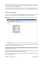
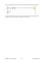
The diagram below shows a typical PLC scan cycle.
SELF TEST
READ INPUTS
RUN LADDER PROGRAM
WRITE OUTPUTS
COMMUNICATIONS,ETC
The PLC reads the inputs from the physical hardware and copies their values to memory. The PLC
ladder program uses the information from memory. This makes the PLC faster and avoids cases
where an input changes from the start to the end of the program.
The PLC steps through the ladder program one rung at a time. The program reads the inputs from
memory and after performing the programmed tasks, the output memory is updated with the output
information.
When the program is complete the physical outputs are updated from the output memory.
The scan time is the time to go once through all of these steps. The part of the scan cycle that is within
the control of the programmer is the ladder program. A short ladder program will result in fast scan times
whilst more complicated programs which make use of many mathematical functions will take longer. It is
up to the programmer to be aware of the response required for the system and to design the program
accordingly.
ioSelect
www.ioselect.com
21
LogiSoft User Manual