1
US006374063B1
(12) United States Patent
(10) Patent N0.:
T0d0me
(54)
(45) Date of Patent:
FIXING DEVICE USED FOR IMAGE
JP
(75) Inventor: Tsuyoshi Todome, Kawasaki (JP)
_
_
_
_
(74) Attorney) Agent) 0,, Firm_FO1ey & Lardner
(JP)
(57)
Sub'ect
to an y disclaimer, the term of this
J
An image forming apparatus is provided With an electro
ABSTRACT
static charging unit, an exposure unit, a developing unit, a
feeding unit, a transfer unit, a peeling-off unit, a ?xing
device and also a cooling mechanism used When taking out
U.S.C. 154(b) by 0 days.
(21) Appl' N05 09/671,154
(22) Filed:
Sep_ 28’ 2000
a jamming sheet in the ?xing device. The ?xing device
consists of a ?xing unit having ?xing rollers and discharge
guide unit for discharging a sheet after ?xed by the ?xing
7
unit. The cooling mechanism, such as, a cooling fan or a
.
(51)
Int. Cl. ....................... .. G03G 15/00, G03G 15/20
(52)
US. Cl. ............................ .. 399/18; 399/22; 399/92
of Search ............................ ..
21, 22,
399/33, 92> 124, 81; 271/273, 272
_
refrigerant Cooling unit, is provided at the discharge guide,
to cool the jamming sheet that has caused jamming only in
the ?xing unit and discharged therefrom~ Time for Cooling
the jamming sheet may be controlled by a user manual
Operation Or for a predetermined period
a recovery
alloWable time, so as not to cool the ?xing rollers, Which
Would otherWise cause a long recovery time. Or, the cooling
References Clted
US PATENT DOCUMENTS
4,025,180 A
3/1992
Primary Examiner—Sophia S. Chen
patent is extended or adjusted under 35
(56)
M6077
* Cited by eXarniner
_
(73) Ass1gnee: Toshlba Tec Kabushlkl Kalsha, Tokyo
Notice:
Apr. 16, 2002
FOREIGN PATENT DOCUMENTS
FORMING APPARATUS
*
US 6,374,063 B1
mechanism may start a cooling operation after detecting that
a door provided at the front of the image forming apparatus
has been opened for taking out the jamming sheet.
*
5/1977 Kurita et a1. ............... .. 399/92
4,391,509 A *
7/1983 Cavagnaro ................. .. 399/18
16 Claims, 8 Drawing Sheets
I_E—LEC—T_R6: I
IsTATIc
L"2
'ECBQRTQLJ
/—
l
I
I
I EXPOSE l~——3
DE“;
I
I0
I
I DEVELOP {W4
I
F___t__j
I
IBEIIIITDING
}
5
I
P
I2
F_____1I
——>ITRANSFER ;—>IPEEL OFF |I——> I3
I..__T___I
.
|_____,____J
I
1
I
6
I5
\
=&
MEDIUM HOLDING
FIXING UNIT
7
MEANS
COOLING
MEANs
”‘
I7
I
|6~
JAM
DRIVE
DETECTING
ADMITTING ~18
MEANS
MEANS
U.S. Patent
Apr. 16, 2002
Sheet 2 6f 8
US 6,374,063 B1
F2IG.
U.S. Patent
Apr. 16, 2002
Sheet 3 6f 8
US 6,374,063 B1
I5
FIG. 3
U.S. Patent
Apr. 16, 2002
Sheet 4 6f 8
US 6,374,063 B1
JAMMING IN FIXING DEVICE
FORCED - COOLING
BUTTUN DEPRESSED
?
DRIVE FORCED—COOLING FAN
N ST 3
5T4
FORCED - COOLING FAN
YES
CONTINUOUSLY DEPRESSED
FORCED-COOLING FAN STOPPED ~ST 5
FIG. 4
U.S. Patent
Apr. 16, 2002
Sheet 5 6f 8
US 6,374,063 B1
JAMMING IN FIXING DEVICE
‘?
FORCED - COOLING
BUTTUN DEPRESSED
‘?
YES
DRIVE FORCED -COOLING FAN
/\_ ST 3
SET-TIME ELAPSED
‘.7
FORCED - COOLING FAN STOPPED
FIG. 5
>—- ST 5
U.S. Patent
Apr. 16, 2002
Sheet 6 of8
US 6,374,063 B1
JAMMING IN FIXING DEVICE
FORCED -COOLING
BUTTON DEPRESSED
DRIVE FORCED‘COOLING FAN
FORCED - COOLING FAN
YES
CONTINUOUSLY DEPRESSED
FORCED-COOLING FAN STOPPED
END
FIG. 6
~ST5
U.S. Patent
Apr. 16, 2002
Sheet 7 6f 8
US 6,374,063 B1
FORCED-COOLING
BUTTON DEPRESSED
v
DRIVE FORCED-COOLING FAN
H—-ST3
NO
SET — TIME ELAPSED
FORCED-COOLING FAN STOPPED A-ST 5
U.S. Patent
Apr. 16, 2002
Sheet 8 6f 8
US 6,374,063 B1
JAMMING IN FIXING DEVICE
DRIVE FORCED-COOLING FAN
ASTB
SET - TIME ELAPSED
‘?
FORCED~COOLING FAN STOPPED
FIG.8
? ST 5
US 6,374,063 B1
1
2
The drive admitting means may include a manual sWitch
FIXING DEVICE USED FOR IMAGE
FORMING APPARATUS
that is provided inside a door provided at a front body of the
image forming apparatus, for the cooling means to start by
BACKGROUND OF THE INVENTION
a user manual operation. Or, it may be an automatic drive
admitting means by Which a sWitch is turned on When the
The present invention relates to an image forming appa
door provided at the front body is opened. Moreover, it is
preferable that, under combination of the manual sWitch and
automatic control, for example, the cooling means is auto
ratus such as a plane paper color copy machine and a printer,
for printing data transferred from an image data supplying
apparatus such as a personal computer and a digital camera,
on plane papers or OHP sheets. Particularly, this invention
relates to a ?xing device having a cooling mechanism for
cooling a medium to be taken out When a paper jam occurs
While ?xing a color material deposited on the medium.
matically driven When the door is opened to cool at once the
10
means, and the cooling means is stopped by means of the
manual sWitch When the medium holding means and the
An image forming apparatus is generally equipped With
an optical unit, an exposure unit, a developing unit, a
paper-feeding unit, a transfer unit, a ?xing unit, and so on.
jamming image forming medium have been cooled enough.
15
The paper-feeding, transfer and ?xing units Would suffer
a paper jam in Which any of the units is jammed by sheets
For automatic control, it is preferable that, after the
driving mechanism of the cooling means has started to drive,
cooling is performed for a ?xed period in Which the drive
mechanism has continued driving until a predetermined
Apaper jam could occur anyWhere in the units to Which
sheets are transferred. When a paperjam occurs in the ?xing
unit that has been generating a high heat, a user has to open
a hinged door of an image forming apparatus to ?nd a unit
jamming sheets (a jam process).
period passes, and the drive mechanism automatically stops
When the predetermined period has passed.
25
The cooling means may, in general, be constituted by a
cooling fan as a cooling mechanism and a motor as a drive
mechanism for rotating the cooling fan. The drive admitting
Such a jam process annoys a user, particularly When it
occurs to the ?xing unit because jamming papers are often
means as a manual operating means thus can be an on-off
sWitch for a cooling fan-driving motor. The cooling means
may be constituted, as a unique con?guration, by a cooling
heated When a hinged door of an image forming apparatus
is opened due to the facts that a paper jam occurs right after
a ?xing process or a heat-generating ?xing unit is very close
mechanism in Which a refrigerant pipe is provided along the
bottom of a receiving plate of the medium holding means,
to the papers.
such as, a discharge transfer guide and a drive mechanism
Rapid cooling to the ?xing unit for taking out the jamming
papers When a paper jam occurs around the ?xing unit could
cause temperature decrease to the ?xing unit While toner has
For drive admission by a manual operation, it is preferable
that the drive mechanism of the cooling means is stopped
When a user has not depressed the manual button anymore.
of paper as an image forming medium on Which an image is
formed.
that has been suffering a paper jam for taking out the
medium holding means and a jamming image forming
medium that is located in the vicinity of the medium holding
for cooling by circulating a refrigerant through the refrig
35
erant pipe of the cooling mechanism.
Con?gured as above, When a paper jam occurs in the
been attached to the unit, the cooled toner being hardly
?xing unit, a discharge transfer guide at the discharge side
peeled off.
and an image forming medium, such as, a jamming sheet
that has been discharged to the discharge side only are
cooled Without cooling the ?xing unit itself. Therefore, a
SUMMARY OF THE INVENTION
Apurpose of the present invention is to provide an image
forming apparatus having a cooling mechanism that offers a
user can take out an image forming medium caught in the
jam process Without annoying a user When performed to a
?xing unit With no uncomfortable feeling When performing
?xing unit, and Without getting a ?xing roller dirty by
cooling only the outlet of the ?xing unit and its peripheral.
a jam process.
Moreover, the medium holding means, such as, a guide at
In order to meet the purpose, a ?xing device of an image 45 the discharge side and an image forming medium, such as,
a jamming sheet located in the vicinity of the medium
holding means only are cooled Without sending a cool Wind
or cool air to the ?xing unit itself, thus no occurrence of
attachment of toner, for example, to the ?xing rollers due to
forming apparatus according to the ?rst basic con?guration
of the present invention is an ?xing device of an image
forming apparatus, heated and ?xed by Which is an image
forming medium transferred on Which is a toner image
formed on an image ?xing body by an electrophotography
process, the ?xing device including: a ?xing unit that presses
and heats the image forming medium to be ?xed by a pair
of ?xing rollers; medium holding means provided at an
outlet side of the ?xing unit for holding the image forming
medium, on Which an image has been ?xed, transferred and
55
discharged from the ?xing unit; jam detecting means for
detecting a jam in Which the image forming medium has
been caught betWeen the ?xing rollers and not moving;
medium transferred on Which is a toner image formed on an
image ?xing body by an electrophotography process, the
cooling means including a cooling mechanism for cooling
the medium holding means and jamming image forming
medium and a drive mechanism for driving the cooling
mechanism; and drive admitting means for admitting the
?xing device including a ?xing unit that presses and heats
the image forming medium to be ?xed by a pair of ?xing
rollers, medium holding means provided at an outlet side of
the ?xing unit for holding the image forming medium, on
Which an image has been ?xed, transferred and discharged
drive mechanism to drive the cooling mechanism to cool the
medium holding means and the jamming image forming
medium located in the vicinity of the medium holding means
When the jamming image forming medium is detected by the
jam detecting means.
cooling. The present invention thus achieves a cooling
mechanism of a ?xing device easy for post-processing.
A method of controlling a cooling mechanism of a ?xing
device according to the second basic con?guration of the
present invention is a method of controlling a cooling
mechanism of a ?xing device of an image forming
apparatus, heated and ?xed by Which is an image forming
65
by the ?xing unit, jam detecting means for detecting a jam
in Which the image forming medium has been caught
betWeen the ?xing rollers and not moving, and cooling
means including a cooling mechanism for cooling the
US 6,374,063 B1
3
4
medium holding means and jamming image forming
opened, and outputting the drive admitting signal to the
drive mechanism; and driving the drive mechanism by
medium and a drive mechanism for driving the cooling
mechanism, the method including the steps of: detecting a
jam in Which the image forming medium has been caught
betWeen the ?xing rollers and not moving by the jam
detecting means; and admitting the drive mechanism to
drive the cooling mechanism to cool the medium holding
means and the jamming image forming medium located in
the vicinity of the medium holding means.
In the method of controlling a cooling mechanism of a
means of the output drive admitting signal.
Moreover, in this method, the automatic admission step
may include the steps of: detecting that a door provided at
a front body of the image forming apparatus has been
opened, thus outputting a drive admitting signal; driving the
drive mechanism of the cooling means based on the output
drive admitting signal; and a manually operating step of
10
manually operating a drive shut-doWn sWitch to stop the
?xing device according to the second basic con?guration,
cooling mechanism.
the step of admitting the drive mechanism to drive may
include the step of driving the drive mechanism of the
cooling means by a user manual operation.
In this method, the step of driving by the user manual
nism of a ?xing device according to the second basic
con?guration of the present invention can basically effec
Accordingly, the method of controlling a cooling mecha
15
operation may be performed by depressing a drive sWitch for
starting the drive mechanism to drive the cooling mecha
tively drive the cooling mechanism of the ?xing device
according to the ?rst basic con?guration. The method thus
achieves effective cooling to the medium holding means at
nism.
the outlet side of the ?xing unit and the image forming
In this case, it is preferable that the cooling means
includes a cooling fan as the cooling mechanism for sending
a speci?c air?oW in a direction of the medium holding
medium transferred and discharged onto the medium hold
ing means, Without cooling the ?xing device itself, and also
Without making a user uncomfortable and attachment of
means and a drive motor as the drive mechanism for rotating
toner to the main mechanism of the image forming appara
the cooling fan, the step of driving by the user manual
operation being performed by depressing a drive sWitch for
starting the drive mechanism to drive the cooling fan pro
vided in the vicinity of the ?xing rollers.
Moreover, in this case, it is preferable that the cooling
tus.
25
In the attached draWings:
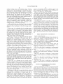
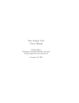
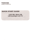
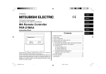
FIG. 1 is a block diagram shoWing a basic structure of a
means includes a refrigerant cooling unit as the cooling
mechanism that is provided at a transfer plate that is
included in the medium holding means, for cooling the
transfer plate by using a refrigerant and a refrigerant circu
lating unit for circulating the refrigerant of the refrigerant
cooling unit, the step of driving by the user manual operation
being performed by depressing a drive sWitch for driving
circulation of the refrigerant of the refrigerant cooling unit
?xing device having a cooling mechanism as the ?rst
embodiment according to the present invention;
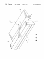
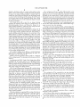
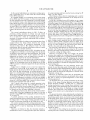
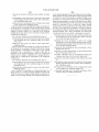
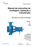
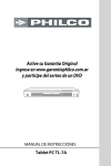
FIG. 2 is a perspective vieW of a discharge guide unit
having a ?xing unit and a cooling mechanism of the ?xing
device according to the ?rst embodiment;
35
provided at an outlet side of the ?xing rollers.
In the method of controlling a cooling mechanism of a
operation of the ?xing device according to the ?rst embodi
ment;
the step of admitting the drive mechanism to drive may
include the steps of: generating a control signal based on the
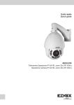
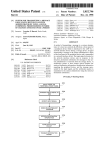
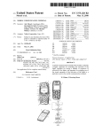
FIG. 5 is a How chart for explaining a cooling control
jam detected by the jam detecting means; and automatic
admission step of automatically driving the cooling means
operation of the ?xing device according to the second
embodiment;
FIG. 6 is a How chart for explaining a cooling control
45
of the image forming apparatus has been opened, thus
outputting a drive admitting signal; and driving the drive
FIG. 7 is a How chart for explaining a cooling control
admitting signal.
FIG. 8 is a How chart for explaining a cooling control
In this case, it is preferable that the cooling means
includes a cooling fan as the cooling mechanism for sending
a speci?c air?oW in a direction of the medium holding
operation of the ?xing device according to the ?fth embodi
ment.
means and a drive motor as the drive mechanism for rotating
55
steps of: detecting that the door at the front body has been
drive motor; and driving the drive motor by means of the
output drive admitting signal.
Furthermore, in this case, it is preferable that the cooling
means includes a refrigerant cooling unit as the cooling
mechanism that is provided at a transfer plate that is
mechanism as the ?rst embodiment.
included in the medium holding means, for cooling the
transfer plate by using a refrigerant and a refrigerant circu
steps of: detecting that the door at the front body has been
DETAILED DESCRIPTION OF PREFERRED
EMBODIMENTS
Preferred embodiments according to the present invention
Will be disclosed With reference to the attached draWings.
Disclosed ?rst is a ?xing device having a cooling mecha
nism (a basic structure) as the ?rst embodiment according to
the present invention With reference to FIGS. 1 to 4. FIG. 1
shoWs a block diagram of a ?xing unit having a cooling
opened, and outputting the drive admitting signal to the
lating unit for circulating the refrigerant of the refrigerant
cooling unit, the automatic admission step including the
operation of the ?xing device according to the third embodi
ment;
operation of the ?xing device according to the fourth
embodiment; and
mechanism of the cooling means based on the output drive
the cooling fan, the automatic admission step including the
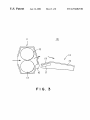
FIG. 3 is a sectional vieW of the discharge guide unit
having the ?xing unit and the cooling mechanism of the
?xing device according to the ?rst embodiment;
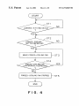
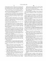
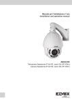
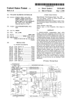
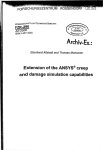
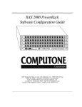
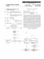
FIG. 4 is a How chart for explaining a cooling control
?xing device according to the second basic con?guration,
based on the control signal.
In this method, the automatic admission step may include
the steps of: detecting that a door provided at a front body
BRIEF DESCRIPTION OF DRAWINGS
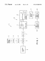
In FIG. 1, an image forming apparatus 1 is provided With
65
an electrostatic charging unit 2 to electrostatically charge a
photo conductor drum; an exposure unit 3 to expose the
charge drum to a document pattern; a developing unit 4 to
US 6,374,063 B1
6
5
The cooling fan 17 has a sWitch 18 provided in the
deposit a developer, such as, a toner on the pattern on the
drum to form a toner image; a feeding unit 5 to feed sheets
of paper as an image forming medium; a transfer unit 6 to
vicinity of the ?xing device 10 inside the image forming
apparatus 1, not on a control panel (not shoWn). If it Were
provided on the control panel, a regular operation could be
obstructed because the control panel Would be locked When
a hinged door (not shoWn) of the apparatus 1 Was opened for
a jam process. The sWitch 18 provided in the vicinity of the
transfer the toner image developed by the developing unit 4
to a sheet fed by the feeding unit 5; a peeing-off unit 7 to peel
off an excess toner from the transferred image; and a ?xing
device 10 to ?x the toner on the transferred image by means
of heat and pressure.
The ?xing device 10 is used for an image forming
apparatus for forming a toner image on a ?xing body by an
electrophotography process and ?xing the image on an
image forming medium to Which the toner image has been
?xing device 10 is noticeable for a user for ease of use.
10
copier recovery time after jamming.
In order to overcome such a problem, a manual operation
transferred by means of heat and pressure.
The ?xing device 10 is provided With a ?xing unit 11
having a pair of ?xing rollers 12 and 13 for ?xing the image
only is offered to the sWitch 18. In detail, the sWitch 18 is not
automatically turned on When a jamming occurs in the ?xing
15
on the image forming medium With heat and pressure; a
medium holding means 14, situated at the outlet side of the
?xing unit 11, to transfer and discharge a sheet “P” as the
device 10 Whereas it is turned on When a user depresses it
While a jamming paper is heated too much for a user to take
out. Moreover, the cooling fan 17 is not driven for a set time,
but it is driven While the user is depressing the sWitch 18.
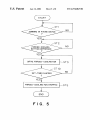
FIG. 4 shoWs a How chart for explaining an operation of
image forming medium on Which the image has been ?xed;
a jam detecting means 16 to detect jamming in Which the
?xing roller 12 and 13 have been stopped due to the sheet
“P” as the image forming means got caught in the gap
betWeen the rollers; a cooling means 17 having a cooling
mechanism for cooling the medium holding means 14 and
the jamming sheet “P” as the image forming means and a
The cooling fan 17 is driven to cool a jamming paper and
also the heat rollers 12 and 13 a little, Which makes long a
the cooling mechanism of the ?xing device in the ?rst
embodiment.
It is judged Whether or not jamming occurs in the ?xing
device 10 in step ST1. Judged next is Whether or not a user
25
drive mechanism for driving the cooling mechanism; and a
drive admitting means 18 to admit the driving mechanism to
drive the cooling mechanism to cool the medium holding
means 14 and the jamming image forming medium adjacent
depresses the sWitch 18 for the cooling fan 17 in step ST2.
If the force-cooling button 18 is judged as being depressed,
the forced-cooling fan 17 is driven in step ST3. It is judged
Whether the forced-cooling button 18 has been still
depressed in step ST4. If it is still depressed, the process
goes back to step ST3 in Which the forced-cooling fan 17 is
continuously driven to cool the top of the sheet that comes
out after getting caught in the gap betWeen the ?xing roller
12 and 13 is shoWn.
to the medium holding means.
The medium holding means 14 has a transfer/discharge
guide 15 for transferring and discharging the sheet “P”
discharged from the ?xing unit 11.
When a user ceases depressing the force-cooling button
Based on the basic structure shoWn in FIG. 1, a structure 35 18, it is judged in step ST4 that the button 18 is not
of the cooling means 17 is disclosed With reference to FIGS.
2 and 3.
As illustrated in FIGS. 2 and 3, the ?xing device 10 is
depressed anymore and then the forced-cooling fan 17 is
stopped in step ST5.
constituted by the ?xing unit 11 and a discharge/transfer
essary cooling operation to the heat rollers at the most.
Jamming in the ?xing device 10 could occur in front of
The manual operation described above avoids an unnec
guide 14 as the medium holding means. The ?xing means
unit 11 contains the ?xing rollers 12 and 13. A jam detecting
and after the ?xing unit 11, hoWever, Will not generate heat
sensor 16 as the jam detecting means is situated at the outlet
so much at the front side. Moreover, the sheet caught in the
gap betWeen the ?xing rollers 12 and 13 is taken out in the
transfer direction. These are the reasons for providing the
side of the casing of the ?xing unit 11.
FIGS. 2 and 3 illustrate the ?xing unit 11 to Which a sheet
as the image forming medium is transferred from left to right
45
in the draWings. Such a sheet is often draWn as transferred
11.
from right to left for a usual image forming apparatus. The
?xing unit is, hoWever, draWn in FIGS. 2 and 3 in this
The cooling fan 17 is controlled by the jam detecting
sensor 16 and the sWitch 18. In other Words, it is driven only
When the jam detecting sensor 16 detects jamming in the
?xing device 10 and also the sWitch 18 is depressed.
speci?cation such that a sheet is transferred in the same
direction as that shoWn in FIG. 1 to match the state With each
other. The direction illustrated in these draWings is decided
in this speci?cation for convenience. The arroWs shoWn in
FIGS. 2 and 3 represent the transferring and discharging
direction for the sheet as image forming medium.
Attached under the discharge/transfer guide 14 at the
?xing unit 11 side is a cooling fan 17 as the cooling means.
On the guide 14 at the part along Which the sheet discharged
from the ?xing unit 11 is guided and Where the cooling fan
cooling fan 17 only at the doWnstream side of the ?xing unit
Jamming occurring at places other than the ?xing device
10 does not alloW the cooling fan 17 to be driven even
though a user unintentionally touches and depresses the
55
17 is attached, slits are formed in the direction of the arroWs
in FIGS. 2 and 3 in Which the sheet is transferred as the
image forming medium.
The slits constitute an opening 19 for cooling. The slits are
formed in the direction of sheet transfer so that they Will not
obstruct the sheet transfer. Moreover, each slit Width is
narroW enough so that an operator cannot insert his or her 65
sWitch 18 While opening the hinged door, thus avoiding
unnecessary cooling of the heat rollers 12 and 13.
The cooling mechanism in the ?rst embodiment shoWn in
FIGS. 1 to 4 performs cooling by a user manual operation
except judgement on occurrence of jamming by the sensor
16.
Not only this, the present invention offers a complete
automatic cooling operation.
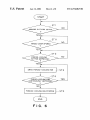
FIG. 5 shoWs a How chart for explaining an operation of
the cooling mechanism in the second embodiment.
The basic hardWare for the second embodiment is the
?nger into any slit While the cooling fan 17 is rotating, to
same as that for the ?rst embodiment shoWn in FIGS. 1 to
secure safety.
3.
US 6,374,063 B1
7
8
In the second embodiment, an automatic cooling opera
tion is performed for a set time When the forced-cooling
of a paper jamming and then stop the forced-cooling fan 17
When a set time elapses.
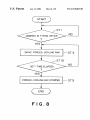
FIG. 8 shoWs a How chart for explaining such a control
button 18 is depressed.
operation of the cooling mechanism of the ?xing device in
It is judged Whether or not jamming occurs in the ?xing
device 10 in step ST1 by means of a detection signal from
the jam detecting sensor 16. If jamming is occurring, judged
the ?fth embodiment.
In FIG. 8, it is judged in step ST1 Whether or not a paper
next is Whether or not a user depresses the forced-cooling
jamming has been occurring in the ?xing device 10 based on
button 18 in step ST2. If it is depressed, the cooling fan 17
a detection signal from the detector 16 as a jam detecting
starts in step ST3. It is judged Whether a set time has elapsed
in step ST10. If not elapsed, the process goes back to step
means. When there is a detection signal from the sensor 16
and it is judged that a paper jamming has been occurring in
the ?xing device 10, the forced-cooling fan 17 is driven to
start in step ST3. After that, it is judged in step ST10 Whether
ST3 to continuously drive the cooling fan 17, Whereas if
elapsed, the process goes to step ST5 to stop the cooling fan
or not a set time has elapsed by a timer (not shoWn), for
17.
The second embodiment shoWn in FIG. 5 offers an
automatic cooling operation in Which, once the sWitch
button 18 is depressed, the forced-cooling fan 17 is driven
15
example. If before elapsing the set time, the process goes
back to step ST3 to continue driving of the cooling fan 17.
On the other hand, if it is judged in step ST10 that the set
time has elapsed, the forced-cooling fan 17 is stopped in step
for a set time by a timer to a jamming paper With no
ST5.
necessity of continuous sWitch depressing, thus avoiding a
The present invention may perform a completely auto
matic cooling control operation like the ?fth embodiment
complex operation.
Care must be taken for taking out the jamming sheet P got
caught betWeen the ?xing rollers, hoWever, the second
embodiment requires no continuous depressing of the
forced-cooling button 18, different from the ?rst
embodiment, thus the second embodiment achieves a quick
jam process and a simple operation.
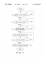
The third embodiment shoWn in FIG. 6 includes the step
of judgement on Whether or not the hinged door is opened,
in addition to the steps for the ?rst embodiment. The fourth
embodiment shoWn in FIG. 7 also includes the step of
judgement on Whether or not the hinged door is opened, in
addition to the steps for the second embodiment.
In FIG. 6 for a control operation to the cooling mechanism
25
With no manual sWitch operation When an object to be
cooled by the cooling means 17 is not the heat rollers 12 but
the top of a sheet caught in the gap betWeen the rollers 12
and 13 at the outlet side of the ?xing unit 11.
The foregoing embodiments are disclosed With reference
to FIGS. 1 to 3 Where the forced-cooling fan 17 cools the
sheet P as the image forming that has caused jamming, so as
to avoid the cooling the ?xing rollers.
HoWever, not limited to this, for example, the present
invention may employ the cooling means 17 constituted by
a refrigerant cooling unit as a cooling mechanism provided
under the transfer guide plate 15 con?guring the medium
holding means 14, that cools the transfer guide plate 15 by
of the ?xing device in the third embodiment, it is judged
means of a refrigerant and a refrigerant circulating unit as a
Whether or not jamming occurs in the ?xing device in step
driving mechanism to circulate the refrigerant in the refrig
erant cooling unit.
In this con?guration, the jam detecting means may
include the jam detecting sensor 16 provided at the outlet
side of the ?xing rollers 12 and 13, like the ?rst embodiment,
ST11 by means of a detection signal from the jam detecting
35
sensor 16.
Judged next is Whether or not a user has opened the
hinged door in step ST11. If the hinged door is judged as
being opened, the process folloWs the same steps shoWn in
FIG. 4 for the ?rst embodiment. A cooling operation con
tinues to a jamming paper While the forced-cooling button
18 has been continuously depressed and When the button 18
is released in step ST4, the forced-cooling fan 17 is stopped
in step ST5. Judgement on Whether or not the front hinged
door of the image forming apparatus 1 is opened is made by
and the manual drive admitting unit 18 may include a
driving sWitch for driving the refrigerant to circulate in the
refrigerant cooling unit.
Moreover, an automatic control may be performed With
an open-door detection sWitch as an automatic drive admit
45
means of a detection signal from a sensor to detect contact
As disclosed above, the cooling mechanism of the ?xing
device of the image forming apparatus according to the
betWeen the apparatus body and the door.
FIG. 7 shoWs a How chart for a control operation in the
present invention includes a cooling fan or a refrigerant
cooling mechanism as the cooling means attached to the
fourth embodiment, like the third embodiment shoWn in
FIG. 6, in Which the forced-cooling fan 17 starts When the
transfer guide as the discharging unit provided at the outlet
side of the ?xing device to discharge an image forming
medium. The cooling fan or the refrigerant cooling mecha
hinged door of the image forming apparatus 1 is detected to
be opened and also the paper jamming is detected.
The difference betWeen the third and the fourth embodi
ment is that, in the latter, judgement on elapse of a set time
is made in step ST10 before stopping the forced-cooling fan
17 in step ST5.
A control operation of the cooling mechanism in the
fourth embodiment achieves double security by detection of
ting unit, to detect an opened hinged-door of the image
forming apparatus 1.
55
nism is driven While a user is depressing the forced-cooling
button.
The present invention, When employing the cooling fan, is
provided With slits as a cooling WindoW in the direction of
transferring copied sheets, at a portion of the transfer guide
of the ?xing devise, at the rear side of Which the cooling fan
the hinged door of the image forming apparatus 1 being
opened and the paper jamming in the ?xing device 10.
The control operations of the cooling mechanism of the
is attached. The cooling WindoW, the slits provided in the
direction of transferring copied sheets, Will not cause any
problem on transfer. Moreover, each slit Width of the cooling
?xing device in the ?rst to the fourth embodiments drives the
WindoW is narroW enough so that a user cannot insert his or
cooling fan 17 to start by depressing the forced-cooling
button 18.
HoWever, not limited to this, the invention includes a
modi?cation to start a cooling operation just after detection
65
her ?nger into any slit While the cooling fan is rotating, thus
causing no injury.
The sWitch for the cooling fan is provided, not on the
control panel, but in vicinity of the ?xing device in the image
US 6,374,063 B1
9
10
forming apparatus. This is because, the control panel Would
be locked When the door is opened for jam processing, if
medium located in the vicinity of the medium holding
means When the jamming image forming medium is
such a sWitch is provided on the control panel; and also the
sWitch provided at a place, such as in vicinity of the ?xing
device, is noticeable for a user, thus being user friendly.
Wherein the drive admitting means includes a manual
detected by the jam detecting means,
drive admitting unit for manually admitting the cooling
Cooled by the cooling fan is not only jamming sheets but
means to be driven.
2. The ?xing device according to claim 1, Wherein the
also the heat rollers Which causes lengthening of a recovery
manual drive admitting unit includes a drive sWitch for
time for a copier after jamming process.
starting the drive mechanism to drive the cooling mecha
nism.
3. The ?xing device according to claim 2, Wherein the
To overcome such a drawback, the present invention is
con?gured such that the cooling fan is not automatically
driven Whenever jamming occurs in the ?xing device but it
cooling means includes a cooling fan as the cooling mecha
nism for sending a speci?c air?oW in a direction of the
is driven only When a user depresses a sWitch Who cannot
take out a heated sheet or do not like to take out such a
heated sheet.
Moreover, cooling is not performed for a set time, in other
Words, the cooling fan is driven While a user is depressing
a sWitch. This arrangement achieves driving of the cooling
fan only for a period required by a user, thus minimiZing
unnecessary cooling of heat rollers.
The cooling fan is provided only the outlet side of the
?xing device for the folloWing reasons:
Firstly, jamming Would occur at any places before and
after the ?xing device, hoWever, its occurrence before a
sheet is taken into the ?xing device mostly generates heat
medium holding means and a drive motor as the drive
15
motor for the cooling fan.
4. The ?xing device according to claim 2, Wherein the
cooling means includes a refrigerant cooling unit as the
cooling mechanism that is provided at a transfer plate that is
included in the medium holding means, for cooling the
25
not so much for a user to take it out. Secondary, a jamming
sheet in the ?xing device is taken out after it is fed in the
5. A ?xing device of an image forming apparatus, heated
and ?xed by Which is an image forming medium transferred
The cooling fan is controlled according to an output of the
jam detection sensor, furthermore, it is driven by depressing
on Which is a toner image formed on an image ?xing body
by an electrophotography process, the ?xing device com
a sWitch only for jamming in the ?xing device. In other
Words, the cooling fan does not start for jamming outside the
prising:
a ?xing unit that presses and heats the image forming
medium to be ?xed by a pair of ?xing rollers;
35
Which an image has been ?xed, transferred and dis
charged from the ?xing unit;
jam detecting means for detecting a jam in Which the
system like the cooling fan. In other Words, the refrigerant
image forming medium has been caught betWeen the
?xing rollers and not moving;
cooling means including a cooling mechanism for cooling
the medium holding means and jamming image form
cooling mechanism sends a cooled air directly to a jamming
sheet via the guide plate 15 so that no cooled air is not sent
toWard the heat rollers 12 and 13, thus the rollers being
prevented from cooling.
45
drive admitting means for admitting the drive mechanism
to drive the cooling mechanism to cool the medium
on Which is a toner image formed on an image ?xing body
by an electrophotography process, the ?xing device com
holding means and the jamming image holding
medium located in the vicinity of the medium holding
means When the jamming image forming medium is
prising:
a ?xing unit that presses and heats the image forming
medium to be ?xed by a pair of ?xing rollers;
detected by the jam detecting means,
Wherein the drive admitting means includes an automatic
medium holding means provided at an outlet side of the
drive admitting unit for automatically admitting the
55
Wherein the automatic drive admitting unit includes a
image forming medium has been caught betWeen the
?xing rollers and not moving;
cooling means including a cooling mechanism for cooling
the medium holding means and jamming image form
door-open detecting sWitch for detecting that a door
provided at a front body of the image forming appara
tus has been opened, thus outputting a drive admitting
signal.
ing medium and a drive mechanism for driving the
6. The ?xing device according to claim 5, Wherein the
cooling mechanism; and
holding means and the jamming image holding
cooling means to be driven according to a predeter
mined control signal after the jam has been detected in
the jam detecting means, and
jam detecting means for detecting a jam in Which the
drive admitting means for admitting the drive mechanism
to drive the cooling mechanism to cool the medium
ing medium and a drive mechanism for driving the
cooling mechanism; and
1. A ?xing device of an image forming apparatus, heated
and ?xed by Which is an image forming medium transferred
?xing unit for holding the image forming medium, on
Which image has been ?xed, transferred and discharged
from the ?xing unit;
medium holding means provided at an outlet side of the
?xing unit for holding the image forming medium, on
closed in the ?fth embodiment.
The refrigerant-cooling mechanism does not spatter heat
soon caused by jamming because it is not an air-cooling
What is claimed is:
transfer plate by using a refrigerant and a refrigerant circu
lating unit as the drive mechanism for circulating the refrig
erant of the refrigerant cooling unit, the manual driving
admitting unit having the drive sWitch for driving circulation
of the refrigerant of the refrigerant circulating unit provided
at an outlet side of the ?xing rollers.
transferring direction.
?xing device even though the sWitch is depressed. This
mechanism prevents unnecessary cooling of heat rollers.
The same advantages are given by the cooling fan that is
con?gured by the refrigerant cooling mechanism as dis
mechanism for rotating the cooling fan, the manual drive
admitting unit having the drive sWitch for driving the drive
65
cooling means includes a cooling fan as the cooling mecha
nism for sending a speci?c air?oW in a direction of the
medium holding means and a drive motor as the drive
mechanism for rotating the cooling fan, the automatic drive
US 6,374,063 B1
11
12
admitting unit having the door-open detecting sWitch for
forming medium and a drive mechanism for driving the
detecting that the door has been opened and outputting the
drive admitting signal to the drive motor.
7. The ?xing device according to claim 5, Wherein the
cooling mechanism, the method comprising the steps of:
detecting a jam in Which the image forming medium has
been caught betWeen the ?xing rollers and not moving
by the jam detecting means; and
cooling means includes a refrigerant cooling unit as the
cooling mechanism that is provided at a transfer plate that is
included in the medium holding means, for cooling the
transfer plate by using a refrigerant and a refrigerant circu
lating unit as the drive mechanism for circulating the refrig
admitting the drive mechanism to drive the cooling
mechanism to cool the medium holding means and the
jamming image forming medium located in the vicinity
of the medium holding means,
Wherein step of admitting the drive mechanism to drive
includes the step of driving the drive mechanism of the
cooling means by a user manual operation.
10. The method of controlling the cooling mechanism of
the ?xing device according to claim 9, Wherein the step of
erant of the refrigerant cooling unit, the automatic driving
admitting unit including the door-open detecting sWitch for
detecting that the door has been opened, thus outputting the
drive admitting signal to the drive mechanism.
8. A ?xing device of an image forming apparatus, heated
and ?xed by Which is an image forming medium transferred
driving by the user manual operation is performed by
on Which is a toner image formed on an image ?xing body
depressing a drive sWitch for starting the drive mechanism
to drive the cooling mechanism.
11. The method of controlling the cooling mechanism of
by an electrophotography process, the ?xing device com
prising:
a ?xing unit that presses and heats the image forming
medium to be ?xed by a pair of ?xing rollers;
20
the ?xing device according to claim 10, Wherein the cooling
medium holding means provided at an outlet side of the
means includes a cooling fan as the cooling mechanism for
sending a speci?c air?oW in a direction of the medium
?xing unit for holding the image forming medium, on
holding means and a drive motor as the drive mechanism for
Which an image has been ?xed, transferred and dis
rotating the cooling fan, the step of driving by the user
charged from the ?xing unit;
jam detecting means for detecting a jam in Which the
25
image forming medium has been caught betWeen the
?xing rollers and not moving:
cooling means including a cooling mechanism for cooling
the medium holding means and jamming image form
fan provided in the vicinity of the ?xing rollers.
12. The method of controlling the cooling mechanism of
the ?xing device according to claim 10, Wherein the cooling
means includes a refrigerant cooling unit as the cooling
mechanism that is provided at a transfer plate that is
ing medium and a drive mechanism for driving the
included in the medium holding means, for cooling the
transfer plate by using a refrigerant and a refrigerant circu
cooling mechanism; and
drive admitting means for admitting the drive mechanism
to drive the cooling mechanism to cool the medium
holding means and the jamming image holding
lating unit for circulating the refrigerant of the refrigerant
35
medium located in the vicinity of the medium holding
means When the jamming image forming medium is
13. A method of controlling a cooling mechanism of a
Wherein the drive admitting means includes an automatic
?xing device of an image forming apparatus, heated and
drive admitting unit for automatically admitting the
?xed by Which is an image forming medium transferred on
Which is a toner image formed on an image ?xing body by
an electrophotography process, the ?xing device including a
cooling means to be driven according to a predeter
mined control signal after the jam has been detected by
the jam detecting means, and
said ?xing device further comprising a manual drive
45
unit, the manual drive admitting unit including a drive
sWitch for starting the drive mechanism to drive the
means for detecting a jam in Which the image forming
medium has been caught betWeen the ?xing rollers and not
moving, and cooling means including a cooling mechanism
for cooling the medium holding means and jamming image
forming medium and a drive mechanism for driving the
that a door provided at a front body of the image
forming apparatus has been opened, thus outputting a
drive admitting signal.
9. A method of controlling a cooling mechanism of a
55
?xed by Which is an image forming medium transferred on
Which is a toner image formed on an image ?xing body by
an electrophotography process, the ?xing device including a
cooling mechanism, the method comprising the steps of:
detecting a jam in Which the image forming medium has
been caught betWeen the ?xing rollers and not moving
by the jam detecting means; and
admitting the drive mechanism to drive the cooling
mechanism to cool the medium holding means and the
?xing unit that presses and heats the image forming medium
to be ?xed by a pair of ?xing rollers, medium holding means
provided at an outlet side of the ?xing unit for holding the
image forming medium, on Which an image has been ?xed,
jamming image forming medium located in the vicinity
transferred and discharged by the ?xing unit, jam detecting
means for detecting a jam in Which the image forming
medium has been caught betWeen the ?xing rollers and not
moving, and cooling means including a cooling mechanism
for cooling the medium holding means and jamming image
?xing unit that presses and heats the image forming medium
to be ?xed by a pair of ?xing rollers, medium holding means
provided at an outlet side of the ?xing unit for holding the
image forming medium, on Which an image has been ?xed,
transferred and discharged by the ?xing unit, jam detecting
cooling mechanism, the automatic drive admitting unit
including a door-open detecting sWitch for detecting
?xing device of an image forming apparatus, heated and
cooling unit, the step of driving by the user manual operation
being performed by depressing the drive sWitch for driving
circulation of the refrigerant cooling unit provided at an
outlet side of the ?xing rollers.
detected by the jam detecting means,
admitting for manually admitting the cooling means to
be driven by controlling the automatic drive admitting
manual operation being performed by depressing the drive
sWitch for starting the drive mechanism to drive the cooling
65
of the medium holding means,
Wherein the step admitting the drive mechanism to drive
includes the steps of:
generating a control signal based on the jam detected by
the jam detecting means: and
automatic admission step of automatically driving the
cooling means based on the control signal, and
US 6,374,063 B1
14
13
wherein the automatic admission step includes the steps
of:
detecting that a door provided at a front body of the image
an electrophotography process, the ?xing device including a
?xing unit that presses and heats the image forming medium
to be ?xed by a pair of ?xing rollers, medium holding means
provided at an outlet side of the ?xing unit for holding the
image forming medium, on Which an image has been ?xed,
forming apparatus has been opened, thus outputting a
drive admitting signal; and
transferred and discharged by the ?xing unit, jam detecting
driving the drive mechanism of the cooling means based
on the output drive admitting signal.
14. The method of controlling the cooling mechanism of
the ?xing device according to claim 13 Wherein the cooling
means includes a cooling fan as the cooling mechanism for
sending a speci?c air?oW in a direction of the medium
holding means and a drive motor as the drive mechanism for
10
cooling mechanism, the method comprising the steps of:
detecting a jam in Which the image forming medium has
been caught betWeen the ?xing rollers and not moving
by the jam detecting means; and
rotating the cooling fan,
the automatic admission step including the steps of:
detecting that the door at the front body has been opened,
and outputting the drive admitting signal to the drive
motor; and
driving the drive motor by means of the output drive
admitting the drive mechanism to drive the cooling
mechanism to cool the medium holding means and the
jamming image forming medium located in the vicinity
admitting signal.
of the medium holding means,
Wherein the step admitting the drive mechanism to drive
includes the steps of:
generating a control signal based on the jam detected by
15. The method of controlling the cooling mechanism of
the ?xing device according to claim 13 Wherein the cooling
means includes a refrigerant cooling unit as the cooling
mechanism that is provided at a transfer plate that is
included in the medium holding means, for cooling the
25
transfer plate by using a refrigerant and a refrigerant circu
lating unit for circulating the refrigerant of the refrigerant
the automatic admission step including the steps of:
detecting that the door at the front body has been opened,
and outputting the drive admitting signal to the drive
mechanism; and
driving the drive mechanism by means of the output drive
admitting signal.
?xing device of an image forming apparatus, heated and
?xed by Which is an image forming medium transferred on
Which is a toner image formed on an image ?xing body by
the jam detecting means; and
automatic admission step of automatically driving the
cooling means based on the control signal, and
Wherein the automatic admission step includes the steps
of:
detecting that a door provided at a front body of the image
cooling unit,
16. A method of controlling a cooling mechanism of a
means for detecting a jam in Which the image forming
medium has been caught betWeen the ?xing rollers and not
moving, and cooling means including a cooling mechanism
for cooling the medium holding means and jamming image
forming medium and a drive mechanism for driving the
forming apparatus has been opened, thus outputting a
drive admitting signal;
35
driving the drive mechanism of the cooling means based
on the output drive admitting signal; and
a manually operating step of manually operating a drive
sWitch to stop the cooling mechanism.
*
*
*
*
*