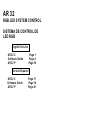
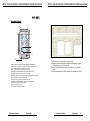
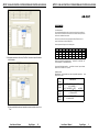
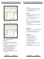
1
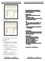
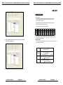
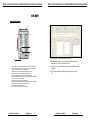
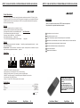
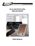
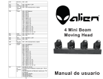
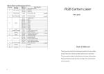
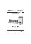
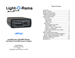
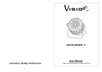
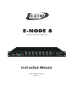
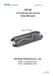
PAGE 1
SHOW
1
PAGE 2
SHOW
2
PAGE 3
SHOW
3
PAGE 4
SHOW
4
AR-32C
SHOW
5
Architectural System
SHOW
6
OFF
PU SH
PUSH
Power IN:
AC 230V~ 50Hz
2
1
2
1. DMX OUT +
2. DMX OUT 3. DMX IN +
4. GND
5. GND
6. 3. DMX IN 7. Vin
8. Vin
SHOW
7
SHOW
8
AUTO (MANUAL)
1
3
3
USB PORT
1=Ground
2=Data3=Data+
Equipson, S.A.
www.equipson.es
[email protected]
DMX IN
DMX OUT
TO AR-32
AR 32
User Manual / Instrucciones de Usuario
AR 32
RGB LED SYSTEM CONTROL
SISTEMA DE CONTROL DE
LED RGB
English Version
AR 32 C
Software Guide
AR 32 P
Page 1
Page 4
Page 10
Versión Español
AR 32 C
Software Guide
AR 32 P
Page 11
Page 14
Page 20
AR 32 RGB LED CONTROL SYSTEM/SISTEMA DE CONTROL DE LED RGB
AR 32 RGB LED CONTROL SYSTEM/SISTEMA DE CONTROL DE LED RGB
AR-32P
AR-32C
Introducción al Producto
Este producto AR 32 P grabador está especialmente diseñado para su uso con unidades AR 32 C. Ofrece potencia para
el sistema AR 32, pudiendo conectarse entre ellas hasta 8 sets para su uso. Las funciones de entrada y salida de señal
DMX, son suministradas por AR 32 P.
Aviso
1. La conexión de tierra debe ser esencial para esta unidad
2. Mantenga la unidad seca, no la exponga al agua o altos niveles de humedad
3. No abra esta unidad, dentro no hay elementos de ajuste para el usuario. RIESGO DE DESCARGAS ELECTRICAS
4. Apague la unidad y desconéctela si no va a usar la unidad durante largo tiempo.
5. Cualquier golpe fuerte o vibración puede ocasionar mal funcionamiento
6. No trate de desmantelar o modificar la unidad
7. Esta unidad debe ser manipulada por adultos, no permita que los niños jueguen con ella.
Main Features
Thank you for your purchase of this product AR 32C-Architectural System.
This product has the main features as below:
Wall mounting & free standing available.
With USB port to communication with PC for linking use
Time call(On/Off) functions to assign trigger time for desired shows individually.
Precaución!
Up to 248 files but not over 128M recorded in memory to control DMX signal files.
Cuando desembale la unidad, compruebe que ésta no ha sido dañada. Si ha ocurrido algo de esto, contacte
inmediatamente con la agencia de transporte.
Reservados todos los derechos. Ninguna parte del manual de este producto puede ser reproducido o transmitido
de ninguna forma o propósito sin la autorización previa.
5
6
3
4
DMX Controlling Mode and Time Trigger Mode and Manual Mode available for
2
1
2
Infrared Remote functions
2
PU SH
PUSH
Power IN:
AC 230V~ 50Hz
1. DMX OUT +
2. DMX OUT 3. DMX IN +
4. GND
Power Failure Memory.
5. GND
6. 3. DMX IN 7. Vin
8. Vin
1
Every effort has been made to design dependable and reliable products. New products
are constantly being designed to meet the needs of the entertainment lighting industry.
Your comments regarding our products and services are welcome. Please send us an
e-mail to [email protected] and let us know how we can improve to better serve you.
3
3
POWER
settings.
invoking shows.
Vista del producto
1
UP to 32 shows assigned separately by professional AR32 configuration software
FUSE
F0.5A 250V 5x20mm
1=Ground
2=Data3=Data+
DMX IN
DMX OUT
TO AR-32
1.Interruptor de red: Permite encender o apagar la unidad.
2.Conector RJ45: Para conectar con un AR 32 C mediante este conector.
3.DMX IN (Conector XLR3): Este conector se usa para recibir señal DMX
4.DMX OUT (Conector XLR3): Para alimentar con señal DMX un pack DMX
5.Fusible de protección: 0.5A AC 250V 5*20mm.
6.Alimentación: AC 230V~50Hz
It is both a privilege and a pleasure serving you.
Especificaciones
This unit incorporates a remote control
with all functions and controls.
So it is possible to access to all shows
chosing page and show. Also this remote
control allows to select operation mode
(Auto/Manual) and off the unit.
Alimentación........................................................................................................................AC230 -50Hz
Fusible ........................................................................................................................F0.5A 250V 520mm
Dimensiones.......................................................................................................................157 74 43mm
Peso.................................................................................................................................aprox 0.2kg
24-004-1839
Rev1.0
User Manual / Manual
Page/Página
20
User Manual / Manual
Page/Página
1
AR 32 RGB LED CONTROL SYSTEM/SISTEMA DE CONTROL DE LED RGB
AR 32 RGB LED CONTROL SYSTEM/SISTEMA DE CONTROL DE LED RGB
AR-32C
Product Complete View
4
2
3
PAGE 1
SHOW
1
PAGE 2
SHOW
2
PAGE 3
SHOW
3
PAGE 4
SHOW
4
AR-32C
1
SHOW
5
Architectural System
SHOW
6
7
5
OFF
8
SHOW
7
SHOW
8
AUTO (MANUAL)
6
9
USB PORT
10
1.SHOW1~8 buttons: To select the desired show in the relative page in Manual Mode.
2.SHOW Indicators: To indicate the corresponding SHOW function state and its indicator will
light up in the Manual Mode when the selected show is activated.
3.PAGE1~4 buttons: To select your desired pages for your shows.
4.PAGE Indicators: Its indicator will light up when your desired page is activated.
5.AUTO/MANUAL button: To activate Auto or Manual function mode.
6.AUTO/MANUAL Indicator: The red indicator shows the Auto function mode has been activated
currently and the blue one for the Manual function mode.
7.OFF button: To close the current Show in Manual function mode.
8.OFF Indicator: The desired show has been closed when OFF indicator lights up.
9.Infrared Sensor: To receive infrared remote signals.
10.USB Port: For communication to PC.
11.RJ45 Connector: For linking use with AR32P.
User Manual / Manual
Page/Página
2
5.7 Repita los pasos 5.1 a 5.6 para editar otros eventos de show
5.8 Después de que esos eventos finalizen, el usuario puede descargarlos al controlador
AR 32 pulsando sobre el icono “Download Event”.
5.9 Además el usuario puede leer estos eventos de shows wn wl AR 32 y modificarlos a
su gusto.
5.10 El usuario puede actualizar el horario de sistema del AR 32 pulsando sobre “Set Time”
User Manual / Manual
Page/Página
19
AR 32 RGB LED CONTROL SYSTEM/SISTEMA DE CONTROL DE LED RGB
AR 32 RGB LED CONTROL SYSTEM/SISTEMA DE CONTROL DE LED RGB
AR-32C
Operation Guide
1.Auto/Manual mode
Press and hold Auto/Manual button down for more 2 seconds to select Auto or Manual
function mode. The red indicator shows the Auto function mode is currently entered and
the blue one for the Manual function mode.
And user can stop the current show by pressing and holding OFF button for more 2
seconds. At this moment, its indicator will light up.
Shows assignments in Pages refer to the following table:
5.5 Una segunda pulsación de la flecha bajo “Event Start” selecciona el tiempo de finalización
del show deseado.
Objects
PAGE1
PAGE2
PAGE3
PAGE4
SHOW1
SHOW1
SHOW9
SHOW17
SHOW25
SHOW2
SHOW2
SHOW10
SHOW18
SHOW26
SHOW3
SHOW3
SHOW11
SHOW19
SHOW27
SHOW4
SHOW4
SHOW12
SHOW20
SHOW28
2.Shows are set up by AR32 configuration software
to "AR32 Configuration Software Operation Guide".
SHOW5
SHOW5
SHOW13
SHOW21
SHOW29
SHOW6
SHOW6
SHOW14
SHOW22
SHOW30
SHOW7
SHOW7
SHOW15
SHOW23
SHOW31
SHOW8
SHOW8
SHOW16
SHOW24
SHOW32
operations in PC and its details refer
3.User can use AR32 Remote Controller to
control AR32 Architectural System. Its buttons
functions are the same with ones of your Ar32.
4.DMX Control Mode
DMX initial address and channel addres ses can be set though AR32 configuration so
setting to control shows:
DMX
Channel
Starting
Channel
Starting
Channel +1
Starting
Channel +2
ftware
DMX Addresses
0~3 For SHOW1, 4~7 For SHOW2,
9~11 For SHOW3, ……
......
124~127 For SHOW32,
128 For closing SHOW.
< 80 access to PAUSE, 80 ~160 access to PLAY
>=160 access to STOP
<128 access to NORMAL OUTPUT
>=128 to BLACKOUT
5.6 Estos eventos editados pueden ser almacenados en memoria pulsando sobre el icono
“Save”
User Manual / Manual
Page/Página
18
User Manual / Manual
Page/Página
3
AR 32 RGB LED CONTROL SYSTEM/SISTEMA DE CONTROL DE LED RGB
AR 32 RGB LED CONTROL SYSTEM/SISTEMA DE CONTROL DE LED RGB
SOFTWARE GUIDE
AR32 Configuration Software is professional application software for AR32 Controller.
Many functions settings through this software application could be directly carried out for
AR32 controller linking your computer via RJ45 cable. Materially, Manual Mode, DMX
Control Mode and Time Trigger Mode are available.
In Windows, click the Start button and go to the “Programs” then “AR-32 Configuration
Software”. Move the pointer to the AR-32 Configuration Software icon, the AR-32
Configuration Software screen appears hereinafter:
5. Opción Event Edit:
Con esta opción, el usuario puede activar el modo Time Trigger de show editando los eventos
de show en el controlador AR 32, incluyendo modo semanal, diario y por fecha.
¿Cómo editar eventos de shows?
5.1 Seleccione el modo de disparo de tiempo (weekly, semanal, Daily, diario, Date, fecha)
5.2 Seleccione los shows a ejecutar
5.3 Pulse sobre “ADD” para editar el tiempo deseado
1. Playing Flash Files:
In MEMO option, 12 different flash files icons will be used to play quickly. Move the
pointer the desired icon and click the right key once, a dialogue box will appear on the
screen.
5.4 Pulse la flecha bajo “Event Start” para seleccionar el tiempo de inicio del show deseado.
Select your desired flash file with extension .swf and click “OPEN” icon, the selected
file will be successfully linked with the icon in the MEMO option and the file name icon
will also appear in the MEMO option.
And click the icon in the MEMO option to play the selected file. Additionally, you can
play the selected file by pointing to the flash file after clicking the “OPEN FLASH” icon
User Manual / Manual
Page/Página
4
User Manual / Manual
Page/Página
17
AR 32 RGB LED CONTROL SYSTEM/SISTEMA DE CONTROL DE LED RGB
AR 32 RGB LED CONTROL SYSTEM/SISTEMA DE CONTROL DE LED RGB
on the right upper.
And the flash effect will appear in the presentation bar. User can use these three icons
to control the flash playing manually. And click the “Play” icon to play the flash,
“Pause” icon to terminate and “Stop” icon to end.
2. FileOption Operation:
FileOption is used to control RGB lightings by adjusting contents of presentation bar.
And up to 170 RGB lightings can be controlled.
2.1 “Fileconvert” icon used to convert the flash file with extension .swf into the file with
extension .scn for AR32 controller playing the one directly.
NOTE:
The “Fileconvert” icon will keep grey during being selected to convert the flash file.
And it will become black after your desired flash file has successfully been converted
Después de pulsar el icono aparece lo siguiente
into the file with extension .scn.
2.2 “Preview” icon used to temporarily play flash files effect by AR32 controlling RGB
lightings.
3. Record Option Operation:
In this option, “Start Record” icon used to start and record DMX signals via AR32 input,
“Pause” icon to terminate the record and “Stop” icon to end the record. And the
segment digits under the “Stop” icon will show the record time for you.
4.7 El usuario puede configurar la dirección inicial DMX para el controlador AR 32 recibiendo
la dirección DMX en la barra y cambiándolos si es necesario.
4.8 ¿Cómo editar un show?
4.8.1 Pulse la flecha DOWN de “Edit Show” para seleccionar el show deseado.
4.8.2 Seleccione el fichero de la lista de la izquierda y pulse el icono “>” para invocar el
fichero deseado
4.8.3 Repita el paso 4.8.2 para invocar más fichero para el show deseado
4.8.4 El usuario puede borrar los ficheros que no quiera dentro del show pulsando el
icono “<” después de marcar los ficheros seleccionados.
4.8.5 Pulse el icono “Insert” para pasar el mismo fichero dentro del show.
4.8.6 Pulse el icono “Save” para almacenar el show en memoria
4.8.7 Repita los pasos 4.8.1 a 4.8.6 para editar otros shows
4.8.8 Por último, el usuario puede descargar los shows editados al AR 32 pulsando el
icono “Save Al Shows”
User Manual / Manual
Page/Página
16
4. Show Option Operation:
In the option, user can assign the SHOW in AR32 controller.
4.1 “DIR” icon use to have files in AR32 readout and list.
4.2 “Read” icon used to read pointed file in AR32.
4.3 “Write” icon used to write files with extension .scn into AR32.
4.4 “Del” icon used to delete pointed files in AR32.
4.5 “Format” icon used to clear up all files in AR32.
4.6 “Edit Show” icon used to start and edit the SHOW in AR32. It is necessary to click
the icon for SHOW readout in AR32.
And hereinafter is before clicking “Edit Show” icon, the left bar of the icon is empty.
User Manual / Manual
Page/Página
5
AR 32 RGB LED CONTROL SYSTEM/SISTEMA DE CONTROL DE LED RGB
AR 32 RGB LED CONTROL SYSTEM/SISTEMA DE CONTROL DE LED RGB
Hereinafter is after clicking the icon.
4.7 User can set up DMX initial address for AR32 controller receiving in DMX Address
bar and amendment upon requirement.
4.8 How to Edit Show?
4.8.1 Clicking the DOWN Arrow of “Edit Show” icon to select your desired show.
4.8.2 Select the file in the left list and click “>” icon to invoke the desired file for
your desired show.
4.8.3 And repeat Step 4.8.2 invoke more files for your desired show.
4.8.4 And user can delete your unwanted files for your desired show by clicking
“<” icon after pointing the selected files.
4.8.5 Clicking the “Inset” icon to invoke the same file with the previous for your
desired show.
4.8.6 And clicking the “Save” icon to save your desired show in memory.
4.8.7 And repeat Step 4.8.1~4.8.6 to edit other desired shows.
4.8.8 At last, user can download edited shows to AR32 by clicking the “Save All
User Manual / Manual
Page/Página
6
User Manual / Manual
Page/Página
15
AR 32 RGB LED CONTROL SYSTEM/SISTEMA DE CONTROL DE LED RGB
GUIA DEL SOFTWARE
AR 32 RGB LED CONTROL SYSTEM/SISTEMA DE CONTROL DE LED RGB
Shows” icon.
El software de configuración para AR 32 es una aplicación para el control por software de AR 32.
Muchas funciones y configuraciones de este software pueden ser realizadas directamente desde
el controlador AR 32 conectado mediante el cable RJ 45. Así pues, los modos de Control DMX,
Manual y Disparo de tiempo están disponibles.
En Windows, pulse la tecla Inicio y vaya a “Programas” y “AR 32 Configuration Software”.
Mueva el puntero al icono de AR=32 Configuration Software, en ese momento aparece la
siguiente pantalla:
5. Event Edit Option:
1. Ejecutando fichero Flash:
En la opción MEMO, pueden usarse hasta 12 ficheros flash para acceso rápido. Mueva el
puntero hasta el icono deseado y pulse la tecla derecha del ratón, aparecerá una caja de
diálogo en pantalla.
In this option, user can activated Time Trigger Mode for SHOW by editing show events
to AR32 controller, including Weekly Mode, Daily Mode and Date Mode.
How to Edit show events?
5.1 To select your desired time trigger modes. “
5.2 And select your desired trigger shows.
5.3 Then click the “ADD” icon to edit the desired time.
5.4 And click the Down Arrow under the “Event Start” icon to select the starting time of
your desired show.
Seleccione el fichero flash deseado con extensión .swf y pulse “OPEN”, el fichero seleccionado
será vinculado al icono seleccionado en la opción MEMO y su nombre aparecerá en esa opción.
Ahora pulse el icono en MEMO para ejecutar el fichero seleccionado. Además puede ejecutar
el fichero seleccionado sin necesidad de grabarlo a una posición MEMO, simplemente pulsando
“OPEN FLASH” en la esquina superior izquierda.
User Manual / Manual
Page/Página
14
User Manual / Manual
Page/Página
7
AR 32 RGB LED CONTROL SYSTEM/SISTEMA DE CONTROL DE LED RGB
AR 32 RGB LED CONTROL SYSTEM/SISTEMA DE CONTROL DE LED RGB
AR-32C
Guia de Funcionamiento
1.Modo Auto/Manual
Presione y mantenga la tecla Auto/Manual durante 2 segundos para seleccionar el modo de
funcionamiento entre Auto/Manual. El indicador rojo muestra la función Auto y si es azul
el modo de funcionamiento es Manual.
El usuario puede detener el show actual presionando manteniendo durante unos 2 segundos
la tecla OFF. En ese momento el indicador OFF se enciende.
Los shows asignados a las distintas páginas, son los siguientes
Objectos SHOW1
PAGE1
SHOW1
PAGE2
SHOW9
PAGE3
SHOW17
PAGE4
SHOW25
SHOW2
SHOW2
SHOW10
SHOW18
SHOW26
SHOW3
SHOW3
SHOW11
SHOW19
SHOW27
SHOW4
SHOW4
SHOW12
SHOW20
SHOW28
SHOW5
SHOW5
SHOW13
SHOW21
SHOW29
SHOW6
SHOW6
SHOW14
SHOW22
SHOW30
SHOW7
SHOW7
SHOW15
SHOW23
SHOW31
SHOW8
SHOW8
SHOW16
SHOW24
SHOW32
2. Software
Los shows pueden ser configurados mediante el software de control. Vea el apartado de “Guía
de control Software” para más detalles.
5.5 Then secondarily click the Down Arrow under the “Event Start” icon to select the
closing time of your desired show.
3. Modo de control DMX
La dirección de inicio DMX canales de direccionamiento pueden ser configurada mediante el software de
control como muestra el cuadro adjunto.
Canal
DMX
Direccionamiento DMX
Canal
de inicio
Canal inicio
+1
Canal inicio
+2
0~3 para SHOW1, 4~7 para SHOW2,
9~11 para SHOW3,......
……
124~127 para SHOW32, 128 para cerrar SHOW.
< 80 accede a PAUSE, 80 ~160 accede a PLAY
160 accede a STOP
< 128 accede a SALIDA NORMAL
128 accede a BLACKOUT
5.6 And these edited events can be saved in memory by clicking the “Save” icon.
User Manual / Manual
Page/Página
8
User Manual / Manual
Page/Página
13
AR 32 RGB LED CONTROL SYSTEM/SISTEMA DE CONTROL DE LED RGB
AR 32 RGB LED CONTROL SYSTEM/SISTEMA DE CONTROL DE LED RGB
AR-32C
Product Complete View
4
2
3
PAGE 1
SHOW 1
PAGE 2
SHOW 2
PAGE 3
SHOW 3
PAGE 4
SHOW 4
AR-32C
1
SHOW 5
Architectural System
SHOW 6
7
5
OFF
8
SHOW 7
SHOW 8
AUTO (MANUAL)
USB PORT
6
9
10
1. Botones SHOW1-8: Para seleccionar deseado en la página relativa en modo Manual.
2. Indicadores SHOW: Indican la función en el Show correspondiente y su indicador se
ilumina cuando se ha seleccionado en el modo Manual.
3. Botones PAGE 1-4: Para seleccionar la página deseada para sus shows
4. Indicadores PAGE: Se iluminan cuando la página deseada se activa
5. Botón AUTO/MANUAL: Para activar el modo de función Auto o Manual
6. Indicador AUTO/MANUAL: El indicador rojo muestra que la función Auto está activada
y pasa a color azul para la función Manual.
7. Botón OFF: Para cerrar el show actual en modo Manual
8. Indicador OFF: El shows deseado ha sido apagado cuando se ilumina el indicador OFF.
9. Sensor infrarrojo: Para recibir señales remotas por infrarrojo
10. Puerto USB: Para comunicación con un PC.
11. Conector Rj45: Para el conexionado a la unidad AR 32P.
User Manual / Manual
Page/Página
12
5.7 And repeat Step5.1~Step5.6 to edit other shows events.
5.8 After these events are finished, user can download edited shows events to your
AR32 controller by clicking the “DownLoad Event” icon.
5.9 In like manner, user can read these desired shows events in AR32 and amend upon
requirement.
5.10 And user want to update your AR32 system time by clicking the “Set Time”
icon.
User Manual / Manual
Page/Página
9
AR 32 RGB LED CONTROL SYSTEM/SISTEMA DE CONTROL DE LED RGB
AR 32 RGB LED CONTROL SYSTEM/SISTEMA DE CONTROL DE LED RGB
AR-32P
AR-32C
Product Introduction
This product AR-32P ARCHI Recorder is specially designed for combination use with the AP-32 unit(s). It offers
main power for the AP-32, and up to 8 sets of AP-32 units can be linked together for user's application. DMX input
and DMX output functions are also provided by this AR-32P. User can get detailed information through reading
this instruction manual carefully.
Características
Gracias por la adquisición de este producto AR 32C de iluminación arquitectual
Este producto tiene las siguientes características principales:
Warning
1.The ground connection should be so essential for this unit.
2.Keep the unit dry, do not expose it to water or high levels of humid.
3.Do not open this unit, there is no user serviceable part insideRisk Of Electric Shock !
4.Turn off the power if not using this unit for a long time.
5.Any strong shocks or vibration may result in malfunction.
6.Do not attempt to dismantle or modify the unit.
7.This unit must only be operated by adults, do not allow children
to play with it.
Disponible para montaje mural o sobremesa.
Puerto USB de comunicación con el PC
Función Time call(On/Off) para asignación de tiempos de disparo a los shows individuales.
Hasta 248 ficheros pueden almacenarse pero sin superar los 128M de memoria para el control de señales DMX.
Caution!
Hasta 32 shows asignados por separado gracias al software incorporado.
When unpacking , please check the unit is not damaged. If something wrong has happened to this product, contact
the local dealer immediately .
All rights reserved . No part of this manual included with this product can be reproduced or transmitted in any form,
by any means for any purpose without authorized
permission.
Modo de control DMX. Modo de disparo por tiempo y Modo Manual.
Función Infrarrojos disponible
Memoria ante fallos de alimentación.
Product View
1
5
6
3
4
2
PU SH
PUSH
Power IN:
AC 230V~ 50Hz
2
1
2
1. DMX OUT +
2. DMX OUT 3. DMX IN +
4. GND
5. GND
6. 3. DMX IN 7. Vin
8. Vin
1
3
3
POWER
FUSE
F0.5A 250V 5x20mm
1=Ground
2=Data3=Data+
DMX IN
DMX OUT
TO AR-32
1.Power Switch: To switch the unit power on or off.
2.RJ45 connector: To connect with an AR-32C unit via this connector.
3.DMX IN (3-pin XLR connector): This connector is used to receive DMX signal.
4.DMX OUT (3-pin XLR connector): To feed the DMX signal to a DMX pack via this connector.
5.Fuse Protection: 0.5A AC250V 5*20mm.
6.Power In: To input AC 230V~50Hz main power via this connector.
Esta unidad incorpora un sistema de
control remoto con todas las funciones
y controles.
Así es posible acceder a todos los
shows eligiendo la página y el show.
Además este mando permite seleccionar
el modo de funcionamiento (Auto/Manual)
y apagar la unidad.
Specifications
Power input..........................................................................................................................AC230 -50Hz
Fuse..........................................................................................................................F0.5A 250V 520mm
Dimensions........................................................................................................................157 74 43mm
Weight.................................................................................................................................approx 0.2kg
24-004-1839
Rev1.0
User Manual / Manual
Page/Página
10
User Manual / Manual
Page/Página
11