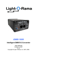
1
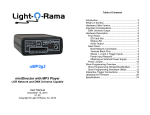
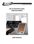
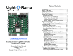
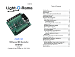
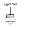
mDM-MP3 miniDirector with MP3 Player User Manual December 15, 2014 V1.02 Copyright © Light O Rama, Inc. 2007, 2008 mDM-MP3 Table of Contents Introduction .............................................................. 4 What’s in the Box..................................................... 4 Hardware Utility Version .......................................... 5 Important Considerations ........................................ 6 Hardware Description .............................................. 7 Front Panel .......................................................... 7 SD Card Slot .................................................... 7 Status LED ....................................................... 7 Audio Output .................................................... 8 Rear Panel ........................................................... 8 RJ45 Network Connection ................................ 8 Terminal Block Pins .......................................... 9 Shows 1, 2 and 3 Trigger Inputs....................... 9 Power Input Reasons ....................................... 9 Attaching an External Power Supply .............. 10 Power Jumper .................................................... 11 Show Programming Overview ............................... 13 Show Programming (SimpleShowBuilder) ......... 13 Show Programming (Hardware Utility <1.6.4) .... 14 Show Programming (Hardware Utility >1.6.4) .... 20 Interactive Trigger Connections ............................. 27 Updating the mDM-MP3 Firmware ........................ 28 Specifications ........................................................ 31 Introduction The Light-O-Rama mDM-MP3 miniDirector with MP3 player is a compact, powerful show director designed to take the place of your PC. It directs a network of LOR controllers while simultaneously playing MP3 audio files. Three trigger inputs allow shows to be started by external events like switch closures or motion detectors. The Windows Showtime software is used to design and build Sequences (light controller commands that may be choreographed to audio/music.) These user created sequences and/or pre-programmed musical sequences available from LOR are then arranged into Shows. These Shows are transferred to an SD card. The SD card is inserted into the miniDirector, which then directs the LOR controllers in your display and plays any associated audio. Interactive Christmas and Halloween displays are possible using the trigger inputs. What’s in the Box Your mDM-MP3 includes a 128 MB (or larger) SD card and a user’s manual. This manual is also available at www.lightorama.com ► Support ► mDM-MP3 User’s Manual. Page 4 mDM-MP3 mDM-MP3 Hardware Utility Version Important Considerations If your Hardware Utility has a LOR MP3 tab on the upper left, you will be able to put a show on the SD card of your miniDirector. If you want to put more than one show on the SD card, you must have Hardware Utility version 1.5.8 or later. If you want to use the trigger inputs, you must have Hardware Utility version 1.6.4 or later. The miniDirector is normally powered by the nearest Light O Rama controller or a USB485B PC adapter. Use a 50’ or less CAT5e LAN cable to connect the miniDirector to either of these devices. Longer cables may have an unacceptable voltage drop that may cause erratic operation of the miniDirector. The version of the Hardware Utility appears in the title bar to the right of “Light-O-Rama Hardware.” If the version number is less than what you require or there is no version number at all, then you need a new Hardware Utility. The latest version is available for download at www.lightorama.com ► Support ► Software Downloads. Click the Download button to the left of the Hardware Utility and run the installer. The miniDirector is NOT weatherproof. SD cards must be formatted FAT16 (or just FAT.) SD cards supplied by LOR will already be formatted FAT16 and ready for use. Not all brands of SD cards will work with the miniDirector. Lexar Media and SimpleTech are known to work. Individual MP3 audio files are limited to 10 minutes. After 10 minutes the audio file will continue to play, but control of the lights will not continue. This does not mean that the miniDirector can only control a 10 minute show, only that no audio file in your show can be longer than 10 minutes. A 128 MB SD card can hold approximately one hour of MP3 audio and controller commands. Songs (audio files) for use with the mDM-MP3 must be encoded as MP3 files. Constant Bit Rate (CBR) at 128K bits/second is best. See www.lightorama.com ► Support ► “How to and considerations: Ripping CDs to MP3s” Page 5 Page 6 mDM-MP3 Hardware Description Front Panel The picture below shows the front panel of the miniDirector. An SD card is inserted into the slot. mDM-MP3 Blinks rapidly if the SD card is invalid or defective. Blinks one long on and a short off repeatedly if in the bootloader. This means that the firmware is not loaded. See the Updating the mDM-MP3 Firmware section to load firmware. Audio Output This is a standard 1/8” stereo mini-jack. It supplies line-level output. You can directly plug headphones or FM transmitter into this jack. Use amplified (powered) speakers or an amplifier with regular speakers. SD Card Slot The SD card is inserted into the SD card slot with the gold connectors facing down. Press the card into the slot until it “clicks” into place. To remove the card, press the card into the slot and it will spring eject. Status LED Blinks once per second if the miniDirector is powered but no SD card is inserted. Steady on during an active show. Blinks off during the show if the network speed is too slow to handle the complexity of the show. Steady on if the miniDirector is connected to the Hardware Utility – no SD card should be inserted when connected to the Hardware Utility. Blinks two short on pulses and then one off pulse repeatedly if the miniDirector is waiting for a trigger input to start a show. Page 7 Rear Panel The picture below shows the back panel of the miniDirector. The RJ45 jack connects to the Light O Rama network of controllers. The six pin screw terminal block allows you to connect show triggers for interactive displays and/or to power the miniDirector from an external power supply. RJ45 Network Connection Use this connector to connect to your controllers, a wireless unit and/or a Windows PC through an RS485 adapter. Page 8 mDM-MP3 Terminal Block Pins Pin 1 2 3 4 5 6 mDM-MP3 the miniDirector is more than 50’ from the nearest controller or the controller is an older model that cannot supply enough power the miniDirector is to be connected to a PC without using a USB485B powered adapter or an attached controller (I.e. using a USB485 or SC485 adapter) the miniDirector is to be put on a timer or switch to start and stop the show (See the Power Jumper section below in this case) the miniDirector is to be used with an RF-V4 wireless unit, so it is not connected to a controller which would power it. Description Start show 1 Start show 2 Start show 3 Ground +5 volts DC output +9 volts DC output –or– +9 volts DC input (Read Attaching Power Warning Below) Shows 1, 2 and 3 Trigger Inputs The trigger inputs (pins 1, 2 and 3) are internally pulled up to +5 volts DC by a resistor and must be connected to ground (pin 4) by a switch. A trigger signal must be at least 11 milliseconds long to guarantee that the miniDirector will detect it. Attaching an External Power Supply When the show is copied to the SD card using the Hardware Utility, you can select whether the trigger switch input for that show is to be normally open (default) or normally closed. A normally open switch closes the circuit when you activate it, a normally closed switch opens the circuit when you activate it. Most motion detectors have normally closed switches and open the circuit when motion is detected. If you attach an external power supply to the miniDirector with incorrect polarity and the miniDirector is connected to one or more controllers and/or a USB485B by a cable, you will most likely burn up the power supplies in the attached devices. Power Input Reasons Connect the positive lead from the 9 volt DC power supply to pin 6 of the rear terminal block. Connect the negative lead to pin 4 of the terminal block. Plug in the power supply and be sure the Status LED on the miniDirector blinks, if it does not, the positive and negative are probably swapped. Try swapping the power supply leads. If the Status LED blinks, the Normally, power is supplied by the attached controller through the RJ45 jack. There are a number of reasons why you may want to use an external power supply with the miniDirector: Page 9 [WARNING: Read carefully] Always disconnect the miniDirector’s RJ45 connection when first connecting an external power supply in case you make a mistake in polarity. Page 10 mDM-MP3 power supply is properly connected. Once the power supply is properly connected, you can safely attach the RJ45 cable to your other devices. Power Jumper The Power Jumper is in place by default and is not normally removed. If you need to access the Power Jumper, remove the four screws from the bottom of the case and lift the top half of the case off. mDM-MP3 Remove this jumper if the miniDirector is to be powered by an external power supply that will be used with a timer or power switch to turn the miniDirector on and off. If the jumper is left on, the attached controllers may continue to supply power to the miniDirector, so it will not obey the timer or power switch. If the miniDirector is not attached to controllers by a cable, but rather by wireless units, then leave the jumper on, otherwise the power from your attached external supply will not reach the wireless unit. Power Jumper Leave this jumper in place if: The miniDirector is to be powered by the nearest controller, the normal case The miniDirector is connected to a PC via an SC485 serial port adapter and no controller is also connected to power the miniDirector and SC485. In this case you will have to attach an external power supply to the miniDirector to power it and the SC485. The miniDirector is not connected to a controller or a USB485B adapter and has an external power supply connected to it and this supply is to be used with an attached RV-V4 wireless unit. Page 11 Page 12 mDM-MP3 Show Programming Overview There are two ways to create an SD card with shows on it for the miniDirector. 1. Simple Show Builder – this application creates a single, non-interactive show. It is simple and intuitive to use. 2. Hardware Utility – this application allows access to the full capabilities of the miniDirector. Multiple shows with interaction are possible. The next three sections explain how to use these tools to create show(s) on the SD card. There are two Hardware Utility version sections. One for the older Hardware Utility versions (prior to 1.6.4) that can not use the interactive triggers, and one for newer Hardware Utility versions (1.6.4 and later) that allow access to the interactive capabilities of the miniDirector. See the Hardware Utility Version section for information on determining and upgrading your Hardware Utility version. The miniDirector does not have a real time clock. Any scheduling information specified during show creation will be ignored. This includes playing shows once per hour or half hour. Show Programming (SimpleShowBuilder) Simple Show Builder is a Light O Rama application that greatly simplifies the creation of a show on the SD card for your miniDirector. It allows you to create Page 13 mDM-MP3 one show consisting of a list of musical and nonmusical sequences without using the Hardware Utility. This show can not use interactive triggers and any scheduling information will be ignored by the miniDirector because it does not have a real time clock. The Simple Show Builder process takes only a few minutes in a small number of self-explanatory screens. Simple Show Builder is available for download at www.lightorama.com ► Support ► Software Downloads. Click the Download button to the left of Simple Show Builder and run the installer. Use Windows Explorer to run the Simple Show Builder by double clicking it. The path to it is usually: C:\Program Files\Light-O-Rama\LORSimpleShowBuilder.exe Show Programming (Hardware Utility <1.6.4) This section describes show programming for the miniDirector with Light O Rama Hardware Utility (HWU) versions 1.5.8 to 1.6.3. These versions of the HWU do NOT support the interactive trigger inputs, but they do support multiple shows. Start the LightORama Control Panel if it is not running by clicking start ► All Programs ► LightORama ► Light-O-Rama Control Panel. The Light-O-Rama light bulb icon will appear in the system tray on the lower right of your screen. Start the Hardware Utility by right-clicking the LightO-Rama Control Panel light bulb and then selecting Hardware Utility from the menu. You will see the following window: Page 14 mDM-MP3 mDM-MP3 Make sure the Old Firmware box in the Scheduling / Show Options section is NOT checked. Make sure the radio button “Play anytime powered” is selected. You can build up to nine (9) shows, their names are Show01, Show02, … Show09. Use this window to set up a single show. When you click the Create Show button later, a new window will pop up allowing you to name this show and set some other options. Only one show can play at a time. Shows play in order from 1 to 9. Use the Select How Show Plays section to chose one of the following: Click the LOR MP3 tab on the upper left and you will see this window: Loop through Showlist continuously – this show will play continuously once it starts Play through Showlist one time only – this show will play through one time and stop Use the MP3 Player Showlist section to add sequences to the show. Add Sequence button to select a sequence to add to this Showlist Remove Sequence button to delete the selected sequence from the Showlist Move Up button to move a selected sequence up in the Showlist Move Down button to move the select sequence down in the Showlist For example, click the Add Sequence button and you will see an Open file box listing the sequences Page 15 Page 16 mDM-MP3 mDM-MP3 loaded on you PC. The sequence file Open window follows: Choose a sequence from this list and click the Open button. The sequence will be added to your show. Now that this show has been setup, you must select some final options and transfer this show to the SD memory card. Click the Create Show button and you will see the following window: Repeat this process until all the sequences you want in your show have been added. In the following example, five sequences (and any associated music files) have been added to the show: Pick a Show number from the Assign this show a number drop-down menu. Page 17 Page 18 mDM-MP3 Use the Final Options section to select the following: Lock Step – This option causes the miniDirector to send all controller commands ahead of time for the next time slice and then give a global “everybody do their commands” command. This has the effect of eliminating the communication line delays when you have a large number of controller/channels. This is a recommended setting. This option is not supported by CTB08 and MC-P cards and requires firmware version 3.0 or above for 16 channel controller cards. Add file to SD card to set the MP3 player’s internal clock – This option will be ignored because the miniDirector has no real time clock. Comm Speed – Use these radio buttons to select the RS485 communications line speed. It is best to leave the speed at 57.6. mDM-MP3 Repeat the above process for each show to be transferred to the SD card. Show Programming (Hardware Utility >1.6.4) This section describes show programming for the miniDirector with Light O Rama Hardware Utility (HWU) versions 1.6.4 and later. These versions of the HWU support the interactive trigger inputs. Start the LightORama Control Panel if it is not running by clicking start ► All Programs ► LightORama ► Light-O-Rama Control Panel. The Light-O-Rama light bulb icon will appear in the system tray on the lower right of your screen. Start the Hardware Utility by right-clicking the LightO-Rama Control Panel light bulb and then selecting Hardware Utility from the menu. You will see the following window: Use the Select Drive with the SD card section to choose the SD card. The drop-down menu will default to the first removable drive on your system. If you forgot to plug the SD card or SD card writer into the PC, do it now and click the Refresh Drive List button. Finally, click the Place Show on the SD Card button to write the current Show to the SD card. You will see this window when it is done: Page 19 Page 20 mDM-MP3 Click the LOR MP3 tab on the upper left and you will see this window: You can build up to nine (9) shows, their names are Show01, Show02, … Show09. Use this window to create up a single show. mDM-MP3 Shows not assigned to a trigger will play in order from lowest numbered to highest numbered while the miniDirector is powered. You specify whether this show plays continuously once it starts or one time only in the Select How Show Plays section. Chose one of Loop through Showlist continuously or Play through Showlist one time only. You can specify whether a show can be interrupted or not. The default is to allow a show to be interrupted by another show being triggered. A triggered show cannot be interrupted by its own trigger. When a triggered show ends, the miniDirector scans for the lowest numbered, untriggered show and starts it, if present. If toggle switches are used as triggers, e.g. to select one of three shows, you must not turn on two triggers at once. If more than one trigger is ‘on,’ the miniDirector will jump instantly between the triggered shows continuously, so no show will actually play. Make sure the Old Firmware box in the Scheduling / Show Options section is NOT checked. In the Select When Show Plays section, select “Show cannot be interrupted by input triggers” if you do not want a triggered show to interrupt the show you are currently building. In the Select When Show Plays section, chose one of the following: Plays anytime powered – This show will not be using an interactive trigger input. You will get to name this show later. Plays when triggered – This show will be using an interactive trigger input. The show will be automatically named by the trigger input you assign to it. How shows are played: Only one show can play at a time. If a show is marked as “Plays when triggered,” it will not play until it is triggered. Page 21 Page 22 mDM-MP3 mDM-MP3 If you select “Plays when triggered” in the Select When Show Plays section, two additional options will appear: 1. Select Switch Number – This assigns one of the three (3) input triggers available on the miniDirector to this show and also sets the show name to Show0n, where ‘n’ is the trigger switch number. Do not use switch numbers 4, 5 or 6. These are not available on the miniDirector. 2. Trigger Switch Type – This selects whether you are using a normally open (NO) or normally closed (NC) switch to trigger this show. Push buttons and pressure mats are usually NO, but motion detectors are usually NC. Use the MP3 Player Showlist section to add sequences to the show: Add Sequence button to select a sequence to add to this Showlist Remove Sequence button to delete the selected sequence from the Showlist Move Up button to move a selected sequence up in the Showlist Move Down button to move the select sequence down in the Showlist Choose a sequence from this list and click the Open button. The sequence will be added to your show. Repeat this process until all the sequences you want in your show have been added. In the following example, five sequences (and any associated music files) have been added to the show: For example, click the Add Sequence button and you will see a Open file box listing the sequences loaded on you PC. The sequence file Open window follows: Page 23 Page 24 mDM-MP3 mDM-MP3 Use the Final Options section to select the following: Now that this show has been setup, you must select some final options and transfer this show to the SD memory card. Click the Create Show button and you will see the following window: Lock Step – This option causes the miniDirector to send all controller commands ahead of time for the next time slice and then give a global “everybody do their commands” command. This has the effect of eliminating the communication line delays when you have a large number of controller/channels. This is a recommended setting. This option is not supported by CTB08 and MC-P cards and requires firmware version 3.0 or above for 16 channel controller cards. Add file to SD card to set the MP3 player’s internal clock – This option will be ignored because the miniDirector has no real time clock. Comm Speed – Use these radio buttons to select the RS485 communications line speed. It is best to leave the speed at 57.6. Important Note: When using interactive shows, all shows should have the same communications speed. If the speed changes from show to show, there will be a 5 second pause to resynchronize between shows. If the speed is the same, a triggered show will start in less than a second. Because this show was assigned to trigger switch 1, its name has been forced to Show01. Page 25 Use the Select Drive with the SD card section to choose the SD card. The drop-down menu will default to the first removable drive on your system. If you forgot to plug the SD card or SD card writer into the PC, do it now and click the Refresh Drive List button. Page 26 mDM-MP3 Finally, click the Place Show on the SD Card button to write the current Show to the SD card. You will see this window when it is done: Repeat the above process for each show to be transferred to the SD card. Interactive Trigger Connections The following diagram shows the connections for a momentary contact switch (A) and a motion detector (B) to a miniDirector. The push button is connected to trigger input 2 and the motion detector is connected to trigger input 1. The push button is a normally open switch, meaning it closes the circuit when activated. The motion detector is a normally closed switch, meaning it opens the circuit when activated. The picture above shows both trigger switches in their ‘off’ (untriggered) position. Page 27 mDM-MP3 The Hardware Utility would be used to configure Show02 for the push button (‘A’) as follows: “Plays when triggered” selected “Select Switch Number” would have radio button ‘2’ selected “Trigger Switch Type” would have radio button “Norm Open” selected. Show01 for the motion detector (‘B’) would be configured as follows: “Plays when triggered” selected “Select Switch Number” would have radio button ‘1’ selected “Trigger Switch Type” would have radio button “Norm Closed” selected. Updating the mDM-MP3 Firmware You must have: Hardware Utility version 1.5.8 or later, see the section Hardware Utility Version No SD card in the mDM-MP3 The mDM-MP3 powered (see the Power Input section) and connected to the PC via one of the RS485 adapters – Do not use wireless Get the latest firmware. www.lightorama.com ► Support ► Using the Hardware – Documentation and Firmware section. Click the Firmware button in the mDM-MP3 line and run the firmware installer. Note the name of the firmware .lhx file. The normal location of firmware files is C:\Program Files\Light-ORama\Firmware. Page 28 mDM-MP3 mDM-MP3 Start the LightORama Control Panel if it is not running by clicking start ► All Programs ► LightORama ► Light-O-Rama Control Panel. The Light-O-Rama light bulb icon will appear in the system tray on the lower right of your screen. Start the Hardware Utility by right-clicking the LightO-Rama Control Panel light bulb and selecting Hardware Utility from the menu. Click the Firmware button in the LOR Control tab and you will see this window: In Step 3 – Press Download Button, click the Download button – the firmware download will start automatically. The Update progress bar will fill from left to right. When the new firmware is loaded, the Status will change to “Successful” and the mDM-MP3 will reboot. In Step 1 – Select Unit, choose the MP3 Player radio button. In Step 2 – Select firmware file, click the Open button. Use the Open file box to select the firmware file. This is the .lhx file you saved in the Firmware folder. Click the Open button. The window will look like this: Page 29 Page 30 mDM-MP3 Specifications Dimensions Storage Power input Interactive trigger inputs Power output 2 5/8”W x 1 1/8”H x 3 3/4"D Up to 2 GB SD card (Lexar Media, Simple Tech) 50 milliamps, 9 volts DC RJ45 network cable from controller(s) – or – Terminal block external power supply 3 (Shows 1, 2 and 3) Each configurable for Normally Open (NO) or Normally Closed (NC) switches Terminal block +5 volts DC (max 200 milliamps) +9 volts DC (current set by power source, max 1 amp) Light-O-Rama, Inc. Tel: (518) 539-9000 Fax: (518) 538-0067 [email protected] Page 31