1
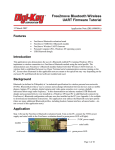
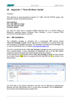
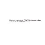
WUTS
USER GUIDE
Revision RB (2015-11-24)
Table of Contents
1
Revision history .............................................................................................................. 4
2
Introduction .................................................................................................................... 5
3
Transferring settings....................................................................................................... 6
3.1
3.2
4
Read and write settings ............................................................................................6
Load and save settings to file ...................................................................................6
Configuration .................................................................................................................. 7
4.1
General ....................................................................................................................8
4.2
Serial port.................................................................................................................9
4.3
Connection .............................................................................................................10
4.3.1
Device settings ................................................................................................10
4.3.2
Security settings ..............................................................................................12
5
Advanced configuration .................................................................................................14
5.1
Notification .............................................................................................................15
5.2
Indication................................................................................................................15
5.3
Scan and output power ..........................................................................................16
5.3.1
Inquiry scan.....................................................................................................16
5.3.2
Page scan .......................................................................................................17
5.3.3
Power settings.................................................................................................17
5.4
Power mode ...........................................................................................................18
5.5
Synchronous connection ........................................................................................19
5.6
HCM.......................................................................................................................19
5.7
Miscellaneous ........................................................................................................20
5.7.1
Class of device ................................................................................................20
5.7.2
Link supervision timeout ..................................................................................20
5.7.3
Performance ...................................................................................................21
5.8
Profile .....................................................................................................................22
6
Hints and tips ................................................................................................................23
6.1
Establishing a connection between two devices .....................................................23
6.1.1
”Non secure” connection .................................................................................23
6.1.2
Paired secure connection ................................................................................24
7
Frequently asked questions/troubleshooting..................................................................25
1 Revision history
Date
NOV 2015
APR 2004
DOC03WUTS-UG-RB
Revision
B
Reason for change
Update due to new software release.
First release
Page 4 of 26
2 Introduction
Free2move have developed an easy-to-use configuration software to assist you in the configuration of
your Uncord and Wireless UART modules. You can configure the Uncord directly via the serial port. The
Wireless UART modules are configurable via the serial port/usb on the evaluation board.
The software can be downloaded from www.Free2move.se and is referred to as WUTS. Install it as
administrator on a computer running Windows™ 7, 8 or 10.
In this document products that can be configured using WUTS are referred to as ‘device’.
DOC03WUTS-UG-RB
Page 5 of 26
3 Transferring settings
3.1 Read and write settings
When changes have been made in the configuring software it is necessary to store the new
settings in the device by pressing the “Write configuration” button in the right of the
information pane.
The settings are stored in persistent memory and are therefore not lost when the power is
removed from the device.
When saving new settings, the previous settings will be lost. If unsure, save a copy of
the default configuration before changes are made (Load and save settings to file).
By clicking the “Read configuration” button the devices current settings will be uploaded to
the WUTS and changed parameters in the graphical user interface will be overwritten and lost.
3.2 Load and save settings to file
In the file menu you are presented with two options for either saving or loading settings. Both
of these options lets you compare the settings in the device and the graphical user interface
to stored settings on your computer.
The “Load settings…” option allows you to load configuration settings from an existing file
on the computer into the WUTS.
The “Save settings…” option allows you to save the current configuration settings in the
WUTS to a file on your computer.
This option can be useful if you wish to apply similar settings to a number of devices. It can
also be used for support matters.
Note that when clicking on “Save settings…” it’s the settings you see in the graphical user
interface that is saved to file.
If you press “Write configuration” and then “Read configuration” before “Save settings…”
you make sure that you have the same settings in the module as in the file you are saving and
that your settings are compatible with the device that you’re configuring.
Before contacting Free2move´s or resellers support departments, please save your
configuration to file and attach this file in the email describing your problem.
DOC03WUTS-UG-RB
Page 6 of 26
4 Configuration
Before configuring your device, you must make sure that there is no Bluetooth connection
present, otherwise the device cannot enter configuration mode. Make sure that no other unit
is connected to your endpoint or that a running corresponding slave unit is not within range of
your connecting device.
To configure your device, attach the device to your computer and choose the serial port
(physical or virtual via USB) that the device is connected to in the drop down list as shown
below.
If the communication with the device fails, check your power supply, make sure you’ve set up
the configuration board correctly and that the device has no active Bluetooth connection.
When you press “Connect” the configuration software initializes, and the following screen
becomes visible:
DOC03WUTS-UG-RB
Page 7 of 26
The configuration application is divided into several tabs. The first three and the most
commonly used are:
1. General settings
2. Serial Settings
3. Connecting settings
The General Settings tab includes version information and device name settings. By
using the Serial settings tab you can configure the serial interface of the device. The
Connecting settings tab is used when configuring the connection management.
The device can be configured to accept connections (endpoint mode) or to connect to
other Bluetooth units (connecting mode).
4.1 General
At the left of the General settings tab, device version information is presented. This information
is useful when in contact with our support and cannot be changed. The Bluetooth Device
Address is a unique fixed number and is shown in some applications when searching for
devices. The Product ID, Hardware and Software version numbers of the device is also
presented.
The Bluetooth Device Name is a user-friendly name that a Bluetooth device presents itself with
when searching for other Bluetooth devices. It is often a good idea to change this name
to simplify the identification of devices. However, if two or more devices have the same name
it can complicate identification and connection to the correct device.
The Bluetooth Service Name is sometimes shown during the Service Discovery. This
procedure is, in most cases, performed when a user initiates a connection to the device. The
device supports one service (Serial Port Profile) and the Bluetooth Service Name is the name
that represents this particular service.
DOC03WUTS-UG-RB
Page 8 of 26
4.2 Serial port
The Serial settings tab is used when configuring the serial interface to the device. The serial
interface of the device can be configured to work with almost every piece of equipment that
uses a serial port.
These setting should be set to the same as those used by your communicating equipment.
The following serial port settings can be configured:
Baud rate
The Baud rate in bauds per second
Parity
You can select the type of parity to be used – none, even or odd
Stop bits
The number of stop bits per word (1 or 2)
Flow control
It is recommended to use hardware flow control in order to prevent data loss and buffers from
being full. This is set by default and is not configurable for F2M03 customers. Contact
Free2move if you want this extra feature.
The number of data bits per word (8) is also shown on this tab. (Not configurable).
DOC03WUTS-UG-RB
Page 9 of 26
4.3 Connection
Configure the module/Uncord to establish a preferred Bluetooth connection to remote devices.
A Bluetooth connection is always made between an initiator (master) and an acceptor (slave).
The initiator device takes initiative to establish a connection to another device, while the
acceptor waits for another device to initiate a connection.
4.3.1
Device settings
The module/Uncord is set to “Acceptor (slave)” and “Accepts all units” by default. If only a
specific Bluetooth device is preferred to connect to as acceptor; disable “Accept all units”
and select the Bluetooth address of the accepted unit. If the Bluetooth address is set to zero
(0 0 : 0 0 : 0 0 : 0 0 : 0 0 : 0 0 ) as by default, any remote device is allowed to connect.
If the device is configured to “Initiator (master)”; select the Bluetooth address of the accepted
unit.
Note: when configured as initiator, the device is not discoverable when another device is
searching for Bluetooth devices.
DOC03WUTS-UG-RB
Page 10 of 26
4.3.1.1
Remote Bluetooth unit
The Bluetooth address can be manually entered or you may use the inbuilt Device search
feature to receive a list of all available Bluetooth units within your range. To start the Device
search feature press the “Find device…” button. Proceed by selecting the Bluetooth unit you
want to accept and click the OK button.
In addition to accepting connections the device can also be configured to connect to
other Bluetooth units. Connecting mode is used to configure the device as Bluetooth master.
This mode will initiate connections with other units that supports the serial port profile. If
the device fails to connect t o the remote device or the connection is dropped it will continue
to try establishing a connection infinitely.
DOC03WUTS-UG-RB
Page 11 of 26
By using the “Find device…” function and double-click a device (or press “Choose selected…”)
WUTS will automatically insert the Bluetooth address of the found device as the “select
accepted unit” in the Remote Bluetooth unit frame as seen in the following picture.
4.3.2
Security settings
There are several options for implementing security to the module/Uncord.
4.3.2.1
Security level
The security configuration determines the level of security required by the module/Uncord
when establishing Bluetooth connections.
There are four levels of security, where “Security off” is set by default:
0.
1.
2.
3.
4.
Security off
Non secure
Service level enforced security
Link level enforced security
Secure Simple Pairing (SSP)
DOC03WUTS-UG-RB
Page 12 of 26
Security mode 0 and 1 allows connections to be established without security. Security mode 2
requires security on service level, i.e. when connecting to the Bluetooth Serial Port Profile
(SPP) service. Security mode 3 requires security on link level, i.e. when attempting to
establish a Bluetooth baseband connection. Security mode 4 requires Bluetooth 2.1 on both
devices and is the easiest and safest security mode.
If you have selected at least security mode “service level enforced security” you may also
select an encryption mode in the Encryption mode frame as an extra security measure.
4.3.2.2
Bluetooth passkey
Some devices require manually entering a passkey, up to 16 characters, to prevent
unauthorized pairing with Bluetooth devices. The Bluetooth passkey for the module/Uncord
is set to “0000” by default.
When a successful pairing has been achieved, the Bluetooth address of the remote device
is stored and is possible to read out in the configuration software “Wireless UART Test Suite”.
DOC03WUTS-UG-RB
Page 13 of 26
5 Advanced configuration
Here you get an overview of the many functions found in the advanced tabs. To get in depth
knowledge of the settings and how they affect your Bluetooth setup, please see datasheets for
the device you are using, Wireless UART user guide and the Bluetooth standard.
The device and Bluetooth modules from Free2move with firmware version 3.0 or more
include commands for fine-tuning the performance and power save modes available on the
devices. Those settings are visible by default but can be hidden by unchecking “Show
advanced settings…” in the Configuration menu.
The advanced settings require that the user have in-depth knowledge of the Bluetooth
technology. Please contact Free2move if you have any questions about how the advanced
settings can improve the performance in your application.
Note! The advanced settings should be used with great care. Do not change anything unless
you are absolutely sure of what the result of your change will be. Changing these parameters
may affect the performance of the device.
When the advanced settings are enabled a number of additional tabs becomes visible in the
configuration software.
DOC03WUTS-UG-RB
Page 14 of 26
5.1 Notification
In the notification tab you can set a way to get notified when a connection is established or
lost.
In the ”Connection established notifiation” frame you can choose a way to get notified when a
connection is established and in the other frame for when a connection is lost or closed.
You can enable the notifications and then choose “notification” from the drop down menu. If
you haven’t written any personal notification at this time and press “Write configuration the
standard notifications will be activated as shown below.
Note that the notifications will be sent in ascii text over the serial port to the host when activated.
5.2 Indication
This tab is for the Uncord only.
In this tab you can choose how the led:s on the Uncord should behave. By disabling them you
can save some power and by enabling them it makes it easy to see when a connection is
established and data is transmitted.
Shown below is the default settings in the Indication tab.
DOC03WUTS-UG-RB
Page 15 of 26
5.3 Scan and output power
The inquiry scan parameters are found on the Scan and output power tab. These settings are
available in all Devices with software version 3.0 or higher.
The inquiry scan and page scan parameters are only applied when the Bluetooth unit is
configured to operate as an Endpoint and as long as there is no Bluetooth connection
established. It is possible to enable and disable inquiry and page scan. The scan interval and
scan window can be modified.
5.3.1
Inquiry scan
When inquiry scan is enabled, the Endpoint unit is discoverable for other Bluetooth units on
inquiry (Device search).
The Scan Interval parameter defines the amount of time between consecutive inquiry scans.
This is defined as the time interval from when the device started its last inquiry scan until the
next.
The Inquiry scan window parameter defines the amount of time for the duration of the
inquiry scan. The
Inquiry scan window can only be less than or equal to the Inquiry scan interval.
By choosing a long interval time and a short window time the average current consumption
can be decreased at the cost of slow response time on inquiry.
By choosing a short interval time and a long window time faster response time on inquiry can
be obtained at the cost of increased average current consumption.
DOC03WUTS-UG-RB
Page 16 of 26
5.3.2
Page scan
When page scan is enabled, the Endpoint unit is connected for other Bluetooth units on page.
The Page scan interval parameter defines the amount of time between consecutive page
scans. This is defined as the time interval from when the device started its last page scans
until it begins the next page scan.
The Page scan window parameter defines the amount of time for the duration of the page
scan. The Page scan window can only be less than or equal to the page scan interval.
By choosing a long interval time and a short window time the average current consumption
can be decreased at the cost of slow response time on page.
By choosing a short interval time and a long window time faster response time on page can be
obtained at the cost of increased average current consumption.
The inquiry and page scan parameters have a span of 11.25ms – 2.56s.
5.3.3
Power settings
The power settings are found on the Scan and output power tab and were added in the 3.0
version of the
Device firmware.
The default transmit power, measured in dBm, is the power used by the Bluetooth radio for
page, inquiry and their scan responses. This is also the initial power used for new connections.
The default transmit power has a valid range of –90dBm to +20dBm, however depending
on the radio power class used and its radio power table, this range is not fully used. It is up to
the user to set the desired value for this parameter and then the module/Uncord will return the
closest value lower than the one requested if the requested is not in the power table. Note that
the default transmit power can’t be set to a greater value than Maximum transmit power.
Setting a lower value than default will decrease the range for the unit. Then it may not be able
to discover or connect to devices far away.
Setting a higher value than default will increase the range for the unit. It might be able to
discover/connect to devices further away, however it may also interfere with devices at close
range, due to sending with too much output power. The consequences might be that the device
will have problems to discover/connect to devices at close range.
The maximum transmit power, measured in dBm, ensures that the local Bluetooth radio
never transmits with higher power than this value.
Maximum transmit power control can be used to adapt the Bluetooth device to follow the rules
and regulations regarding output power for certain countries but also be used for reducing the
range and power consumption of the unit.
DOC03WUTS-UG-RB
Page 17 of 26
Once a successful connection has been established, it is possible to control the remote
device's transmit power (if the remote device supports power control). The remote device can
request an increase or decrease of transmit power depending on how "strong" the signal is.
The maximum transmit power is only referenced when increasing the local transmit power. Our
devices supports power control.
The maximum transmit power has a valid range of –90dBm to +20dBm, however depending
on the radio power class used and its radio power table, this range is not fully used. It is up to
the user to set the desired value for this parameter. The table below shows an example with
suggested value.
The values of the Default TX power and Maximum TX power parameters will be rounded down
to the next available value when set, so the value set may be less than the requested. The
Bluetooth device uses the highest value in the radio power table that is less than or equal to
the requested default transmit power. The actual default transmit power used can be read after
the settings are written to the device
5.4 Power mode
The Wireless UART firmware implements a low power state machine that can be enabled to
save power on low data rate links.
You can read more about this in the Bluetooth standard and in our datasheet for the Wireless
UART firmware.
DOC03WUTS-UG-RB
Page 18 of 26
5.5 Synchronous connection
The settings in this tab are very important not to change if you don’t fully understand how they
affect you setup since they have great impact on performance and compatibility.
Please see Wireless UART user guide for more information about the various commands and
how they can improve your case.
This tab is faded for the Uncord since these settings only are possible for our modules.
By default the synchronous connection commands are disabled.
Shown below is just an example of possible settings.
5.6 HCM
The HCM tab contains a drop down menu which let you decide when the module is allowed to
switch to Host Controlled mode i.e. get connected by the WUTS.
Default setting is “After UART data is sent”.
DOC03WUTS-UG-RB
Page 19 of 26
5.7 Miscellaneous
5.7.1
Class of device
The Class of device parameter was introduced in software version 3.0 of the device. It can
be found under the “Other” tab in the configuration software.
The class of device parameter is used to indicate the capabilities of the device to other devices,
i.e. indicating what type of device it is. For example, when searching for other devices with a
Bluetooth mobile phone, each device discovered would have a symbol associated with it to
give the user an easy overview of what type of device it is. A headset would appear with a
symbol that looks like an earphone and a laptop or desktop workstation would appear as a
computer.
A number of different device classes can be set using the drop-down lists in the configuration
software. If a class of device cannot be created with the use of these lists, the user can
manually enter a class of device value. This is done by enabling the “Enter CoD value
manually” and enter a class of device value in the “CoD Value” field.
See Bluetooth Assigned Numbers for more information about the class of device. The default
class of device value of the device is set to 001F00 which equals to uncategorized.
5.7.2
Link supervision timeout
The link supervision timeout setting can be found under the “Miscellaneous” tab in the
configuration software.
A Bluetooth connection may break down due to various reasons such as a device moving out
of range or a power failure condition. Since this may happen without any prior warning, it is
important to monitor the link on both the Connecting and the Endpoint side. To be able to
supervise link loss, both the Connecting and the Endpoint use link supervision timers.
If at any time in connected state, the timer reaches the supervision timeout value, the
connection is reset. The timeout period is then negotiated again upon a new established
Bluetooth connection. Its value must be chosen so that the supervision timeout is longer than
the low power save modes sniff mode and park mode periods if they are used.
DOC03WUTS-UG-RB
Page 20 of 26
The link supervision timeout has a span of 1–40 seconds.
Note: Short supervision timeout can make the connection unstable. See the Bluetooth
specification and our data sheet on the Wireless UART firmware for more information.
5.7.3
Performance
When a successful Bluetooth connection has been established to a remote device; the device
can be optimized for either throughput or latency mode. The throughput/latency mode
configuration allows the user to fine-tune the low-level settings associated with the UART.
Throughput mode attempts to maximize the throughput at the cost of moderate latency. If low
latency is more important than maximizing throughput, then latency mode may be selected
instead.
When optimized for latency - the UART driver is more aggressive at looking for subsequent
data bytes at the cost of an increased CPU load; hence the tradeoff against throughput.
Optimization of the device/Uncord for latency or throughput was added in the 3.0 version of
the device firmware.
The Link Manager of the Device firmware also provides Quality of Service (QoS) capabilities.
“Best effort” and “Guaranteed” service types are supported.
A poll interval, which is defined as the maximum time between subsequent transmissions
from the master to a particular slave on the ACL link, is used to support bandwidth allocation
and latency control. The poll interval is guaranteed in the active mode except when there are
collisions with page, page scan, inquiry and inquiry scan. The poll interval is also known as
Tpoll.
Connections are given a “Best effort” service type with a Tpoll value of 40 slots (25msec), by
default, when created by device running as master (connecting).
If a different service type and/or Tpoll value for the established connection is desired, a
QoS_Setup command must be sent to request other parameters to be used instead. The
Quality Of Service parameters in the configuration software specify the parameters that will be
used in the QoS_Setup command. The QoS_Setup command (if enabled) will be sent when a
successful connection is established and can be sent by the master as well as the slave. The
requested parameters can be rejected, e.g., if QoS_Setup is sent from a slave the master
may reject the change. The user can only set the desired parameters for the link, it does not
know the actual parameters negotiated.
DOC03WUTS-UG-RB
Page 21 of 26
Being able to adjust the link's Tpoll value allows reduction of the maximum latency for
starting data transfers from slave to master at the cost of extra polling (and thus power
consumption) on the master.
The service mode and latency parameters of the QoS_Setup command can be configured, the
other parameters are not configurable and are set to its default values.
The latency parameter is translated from microseconds to piconet slots (rounded down) and
used in an attempt to set the connection's Tpoll value. The Tpoll value is also subjected to
some limits.
The service mode parameter indicates the level of service required.
If “Best effort” is selected, the service type does not require any guarantees. The fields of the
QoS_Setup ougt to be treated as hints by the remote device. The remote device may choose
to ignore the fields, try to satisfy the hint or respond with the settings it will try to meet.
If “Guaranteed” is selected, the remote device will “guarantee” the latency. This allows the
master to boost the connection´s priority when using sniff mode, allowing for short, tight sniff
timing.
5.8 Profile
If your application requires the device to be a DUN compatible Bluetooth device you can
change this in the drop-down menu.
Default setting is “SPP, Serial Port Profile”.
DOC03WUTS-UG-RB
Page 22 of 26
6 Hints and tips
6.1 Establishing a connection between two devices
In order to use two devicess as a serial link (replacing a serial cable), they must have a
connection between each other. To ensure operating success, one device must be in
connecting mode – Bluetooth master and the other device in endpoint mode – Bluetooth slave.
The connecting unit issues a connection request and the endpoint unit accepts the connection
request based on a connection rule. This implies that both units cannot be in connecting or
endpoint settings mode simultaneously.
There are many different configuration options existing that will allow for the desired
functionality. In this section two different options will be described, one is an easy to configure
option whilst the other option is more secure. The secure option involves a complete Bluetooth
pairing procedure, allowing encryption etc.
In this section the overall procedure is described. To get detailed information about each step
please read the corresponding section of this user manual. Also note that you may have to
configure the serial port settings and the general settings in order to suit your needs.
6.1.1
”Non secure” connection
The easiest way to configure two devices is probably to establish a connection without
authentication. This option will not require two versions of the Free2move Configuration
Software running simultaneously, i.e. only one serial port and one computer is needed.
By using the following configuration steps no other ordinary Bluetooth units will have the
possibility to communicate with the two devices. However it will be possible for one with indepth Bluetooth knowledge to eavesdrop on the traffic and to connect to the units. If used in
applications where security aspects are important please see the Paired secure connection
section below.
The first step in configuring your devices is to determine which device will be master and
corresponding slave. You are helped by knowing the Bluetooth device address of both units.
The address can be seen on the label of the Uncord or by using the configuration software
(General tab).
Start by configuring the endpoint:
Attach the plug that will be the endpoint (Bluetooth slave) to the serial port and start WUTS.
Slave configuration settings are found under the “Connection” tab. Select “Endpoint (slave)”
in the Device mode settings frame and choose the “Security off” option. The next step is
to enter the Bluetooth address of the Connecting unit in the “Select accepted unit (Bluetooth
address)” boxes. It may be necessary to uncheck the “Accept all units” check box before
entering the address. You can also use the “Find device…” function to look up the device
you want to pair with. Note that you can only find devices that are configured as endpoints or
connecting devices that are in configuration mode i.e. connected to WUTS.
DOC03WUTS-UG-RB
Page 23 of 26
Click the “Write configuration” button to save the new settings to memory. Exit the
configuration software.
Continue with the connecting unit:
Attach the plug that will be the connecting unit (Bluetooth master) to the serial port and start
WUTS.
Master configuration settings are found under the “Connectin” tab. Select “Connecting
(Master)” in the Device mode settings frame and choose the “Connect without passkey”
option.
The next step is to enter the Bluetooth address of the Endpoint unit in the “Connect to
(Bluetooth address)” boxes.
Click the “Write configuration” button to save the new settings to memory. Exit the
configuration software. Now your devices should be correctly configured to replace a serial
cable.
6.1.2 Paired secure connection
When using this method to establish a connection between your two Devices; the configuration
procedure is carried out in order to establish a link key. This key will be used both for the
authorization of future connections and for the encryption/decryption of data flow between the
devices.
The first step in configuring your devices is to determine which device will be master and
corresponding slave. Also, make sure that both devices are powered on and connected to
serial ports that have access to the Free2move Configuration Software. Note that you will need
to have two instances of the configuration software running simultaneously connected to the
different serial ports. It is possible to do this on the same computer or by using two computers.
Start by configuring the slave:
Slave configuration settings are found under the “Endpoint settings” tab. Select “Endpoint
(slave)” in the Device mode settings frame. Select security mode 3 or 4. Set a Bluetooth
passkey to something unique and remember to use the same code for the connecting device.
Now start configuration of the master:
Master configuration settings are found under the “Connecting” tab. Select “Connecting
(Master)” in the Device mode settings frame and use the “Find device…” function or
manually enter the Bluetooth device address for the endpoint. Remember to enter the same
passkey as for the endpoint.
Save the new configuration to memory by clicking on the “Write configuration” button.
If the endpoint is no longer connected to WUTS your connection is established seconds after
you release your connecting device from configuration mode by clicking “Disconnect”.
DOC03WUTS-UG-RB
Page 24 of 26
7 Frequently asked questions/troubleshooting
1. My device plug does not enter configuration mode during the initial setup.
Before configuring your device you must make sure that it has no Bluetooth connection
present, as this prevents the plug from entering configuration mode. Also make sure
that your device is powered correctly. If you’re using our evaluation board make sure
that the physical settings is correct i.e. communicating via USB or serial port.
2. Is it possible to connect my device to Bluetooth units from other manufacturers?
Yes, if the other unit supports the Serial Port Profile or RFCOMM it should work
correctly. As a matter of fact this is one of the cornerstones of the Bluetooth technology.
3. I want to connect to the device from another Bluetooth equipped unit like a
Laptop or PDA, What is the preferable configuration?
If security is unnecessary configure the device as an endpoint that allows all units to
connect to it. Then you will be able to use the user interface of the Laptop or PDA to
search and connect the device.
4. I cannot make a connection between my two devices.
To ensure operating success, one device must be in connecting mode – Bluetooth
master and the other device in endpoint mode – Bluetooth slave. Both units cannot be
in connecting or endpoint settings mode simultaneously. (Also se Hints and tips,
Establishing a connection between two devices in chapter 3).
5. When sending or receiving data it seems to be corrupted?
Ensure that the serial settings of the device and your communicating equipment are
the same.
6. I miss some functionality or features, what can I do about this?
Additional settings, functionality and configuration may be introduced. Free2move can
also offer customized solutions to fulfill your requirements. All devices does not support
all features in WUTS but this is shown with a message as you hoover with your pointer
over a non-active tab area in the WUTS.
DOC03WUTS-UG-RB
Page 25 of 26
Contact information
For support questions please contact Free2move support: free2move.se/support/
Copyright
Copyright © 2015, Free2move AB. All rights reserved
Trademark
Windows® is a registered trademark of Microsoft Corporation
Bluetooth® is a registered trademark of Bluetooth SIG, Inc., U.S.A.
Disclaimer
The information given herein includes text, drawings, illustrations and schematics that are believed to
be reliable. However, Free2move makes no warranties as to its accuracy or completeness and disclaims
any liability in connection with its use. Free2move will in no case be liable for any incidental, indirect or
consequential damages arising out of sale, resale, use or misuse of the product. Users of Free2move
products should make their own evaluation to determine the suitability of each such product for the
specific application.
DOC03WUTS-UG-RB
Page 26 of 26