1
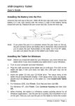
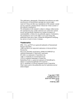
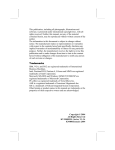
GEM GRAVURE COMPANY, INC
Gem
Type AM Marker
Parts and Assembly Manual
Gem Type AM Marker
Copyright 2007, GEM Gravure Company, Inc All rights reserved.
This document is the property of GEM Gravure Company, Inc and contains confidential and proprietary information
owned by GEM Gravure Company, Inc. Any unauthorized copying, use or disclosure of it without the prior written
permission of GEM Gravure Company, Inc is strictly prohibited.
GEM Gravure Company, Inc.
112 School Street
West Hanover, MA 02339
Tel: (781) 878-0456
Fax: (781) 878-9360
E-Mail: [email protected]
2
Type AM Marker With Stand
GEM Type AM Marker
Shown With Options, Options sold separately.
It is the responsibility of the user of this equipment to provide his employees with a
safe place to work, including proper tools, devices, and safety equipment.
It is essential that all personnel operating this equipment be instructed by their
supervisors in safety precautions as outlines on the following pages as well as proper
operating procedure.
Do not make any adjustments of the machine without first shutting off all electrical
power and air.
3
Gem Type AM Marker
Introduction
The Gem Type AM Marker has been designed to mark wire, cable or pipe up to 3-inches in diameter at
operational speeds.
• The machine accommodates standard marking wheels which utilize flat, concave or convex printing
surfaces photo-engraved for striping, numbering or lettering.
•
As delivered, the machine is set up and ready for use with marking wheels ordered.
•
For high-speed drying and clean, sharp impressions, it is essential that Gem inks be used. Gem
formulates and processes a full line of inks for marking wire- and cable- coverings of natural or
synthetic rubber, polyvinyl chloride, nylon, polyethylene or “Teflon.”
•
Properly maintained and cleaned, the Gem Type AM Marker can be expected to provide years of
dependable service.
Set Up & Operation
•
Locate the marking machine between two water troughs in the extruding line. The first
trough should be of relatively short length (Cf. Note 1). Also, it should be equipped with
a portable sponge weir (or dam) and should have one or more air-wipers at the outgoing
end. The second trough should be of standard length.
•
Note 1: The length of water in the first trough should be shortened by use of sponge dam
to the point where, as the hot insulated wire emerges from the cooling water, the surface
of the wire is covered with beads of water. Under this condition the air wipers drive off
the remaining water from the surface most effectively.
•
Adjust the height of the machine so that the wire-run passes between the bottom marking
wheel and the upper guide wheel. Under operating tension the wire should just clear the
bottom marking wheel. It should be necessary to crank down the guide wheel, applying a
slight pressure, in order to bring the wire in contact wit the printing surface of the
marking wheel.
•
Center the marker so that the wire is directly over the etched legend on the marking
wheel. Once the guide wheel is lowered to apply pressure on the wire, slight centering
adjustments can be made by loosening the shaft-housing lock screws on the back of the
machine and sliding either the top or bottom shafts in or out.
4
Gem Type AM Marker
•
Install wiper holder, selecting proper holder and wiper for the style of marking wheel in
use (i.e., flat wiper holder for flat surface wheel; concave holder for concave surface
wheel).
•
Flat wiper holders use a precut, flat, poly or nylon blade, usually 1 ½” x ½” x 1/8”.
•
Concave wiper holders use round poly or nylon rod of varying diameters, depending on
the size of the concave marking wheel in use.
•
Note: Wiper rod is furnished in one foot lengths, usually 1 ¼” long. One end should be
cut cleanly at a 30° angle. The wiper rod should be positioned and clamped in the wiper
holder so that the angled edge fits into the concave face of the marking wheel when the
wiper is positioned against the wheel.
•
All the wiper holders are made to allow a small clearance between the wiper-holder side
fingers and the sides of the marking wheel when positioned within the wiper.
•
Mounted on the machine, the wiper holder should be at an approximately 15° angle,
when contacting the printing face of the marking wheel. To accomplish this, it may be
necessary to reposition the wiper-holder support assembly. Test the positioning by
attaching the tension spring and cranking a slight degree of pull on the spring forcing the
wiper edge against the marking wheel. Turn the wheel by hand to see if the wiper edge
contacts the full face of the wheel.
•
Proper wiping is essential, since the insulated wire must be clean and dry for good
printing. It is not necessary to exert considerable tension on the wiper. If positioning is
correct, and if the wiper edge is sharp and clean, wiping will be accomplished easily and
with minimum tension.
•
Excessive wiping tensions wear out wipers quickly. Further, the added top pressure
required to make the wire overcome the added drag on the marking wheel causes splayed
or blurred printing and shortens the life of the etched printing surface.
Fill the inkwell only to a point where the ink covers approximately ½” of the bottom of
the marking wheel. This is sufficient to provide a puddle of ink under the wiping edge of
the wiper holder. Excessive filling will result in ink being splashed over the wire and the
equipment.
5
Gem Type AM Marker
•
Ink cans should be thoroughly shaken before use each day. When not in use, cans should
be capped.
Ink viscosities vary according to application but, for most purposes, the ink should
approximate the consistency of light coffee cream.
•
Under operating conditions the viscosity level of the ink can be controlled by the solvent
dripper. Filled with thinner, this attachment can be set to allow one drop of solvent to
penetrate the ink in the inkwell every 5 to 8 seconds.
After completing the run, the ink remaining in the inkwells may be poured back in the
can for re-use, provided the ink is relatively free of impurities. If the ink has been mixed
with water or otherwise adulterated, do not return to can, but discard.
•
The inkwells should be cleaned before re-filling for the next run.
•
The marking wheels should be washed in a solvent and cleaned as soon as possible after
use. Care should be taken to prevent ink from caking on the wheels.
6
Gem Type AM Marker
Procedure to Reverse Marker Direction
1. Remove wiper holder.
2. Remove slide plate assembly to opposite side of machine. Make sure that the wiper
support pin is in the same relative position in order to keep the proper angle between
wiper holder and the marking wheel.
3. Remove the two 10-32 x 3/8 flathead screws that fasten the wiper tension assembly to
the base casting. Turn the wiper tension assembly around, reversing position. Insert
screws and fasten to the opposite side for the base casting.
4. Replace wiper holder on the side with the re-positioned slide plate and wiper tension
assemblies.
5. Interchange the top and bottom shaft assemblies. This is necessary to provide the
proper thread direction to keep roll nuts from loosening when marker is running.
6. If machine is equipped with a solvent dripper, remove and install on the opposite side.
•
The marker is now ready to operate in the reverse direction.
7
Gem Type AM Marker
Type AM Marker Exploded Parts View
8
Gem Type AM Marker
Parts List
Ref. No.
1
2
3
4
5
6
7
8
9
10
11
12
13
14
15
16
17
18
19
GEM Part No. Generic
Part No.
40-1001
61-1
40-1002
61-7
40-1003
61-2
40-1004
61-3
40-1005
61-5
96-0046
40-1006
61-36
96-0712
40-1007
40-1008
61-6
40-1009
61-4
96-0706
40-1010
61-10
40-1011
61-9
40-1012
61-19
40-1268
61-34
96-0216
40-1014
61-20
61-64
20
21
22
23
24
25
26
27
28
29
30
31
32
33
34
35
96-0026
40-1015
40-1016
40-1102
40-1017
96-0703
40-1018
40-1019
96-0028
98-0237
40-1020
96-0702
40-1021
40-1022
96-0014
40-1023
36
37
38
40-1024
96-0027
40-1025
Name
Base Casting
Adjustable Wheel Carrier
Top Plate
Top Roll Adjusting Screw
Top Roll Adjusting Screw Spring
¼ - 20 x 5/8” Hex. H. Cap Screw
Hand Wheel
¼ - 20 x ¼” Socket Head Cup Point Set Screw
¼” Burr
Carrier Plate
Top Roll Adjusting Screw Collar
10 – 32 x 1/8” Socket Head Cup Point Set Screw
Brass Plug for Lock Screw
Bearing Housing Lock Screw
Slide Plate
Adjusting Knob
3/8 – 24 x 1-1/4” Hex. H. Cap Screw
Wiper Support Arm
Wheel Wiper (See page 4 for various sizes of flat
and concave wipers)
¼ - 20 Jam Nut
Wheel Wiper Stud
Wiper Spring (Tension)
Split Key Ring 5/8” I.D.
Tension Adjusting Bracket
10 – 32 x 3/8” Flat Head S.C.S
Knob for Wiper Blade Tension Screw
Wiper Blade Tension Screw
¼ - 20 x ¼” Cup Pt. Soc Set Screw
E-Clip
Tension Follow Nut
10 – 32 x 3/8” Button H. Soc. Cap Screw
#10 Internal Lock Washer
Ink Reservoir Pins
¼ - 20 x ½” Hex. H. Cap Screw
Ink Reservoir (See page 4 for various types of ink
reservoirs)
Rear Roll Nut
1/4 – 20 x 5/16” Cup Pt. Soc. Set Screw
TruArc Retaining Ring
61-28
61-27
61-47
61-110
61-68
61-69
98407A120
61-26
61-22
61-21
61-38
5000-112
9
Gem Type AM Marker
Ref. No.
39
40
41
42
43
44
45
46
*47
GEM Part No. Generic
Part No.
40-1273
R-8
40-1266
40-1028
61-12
40-1029
61-13
40-1030
61-16R
40-1031
61-16L
40-1032
61-17R
40-1033
61-17L
40-103
61-42
Name
Wavy Spring Washer
Bearings
Bearing Spacer
Bearing Housing
Wheel Shaft (R. H.)
Wheel Shaft (L.H.)
Roll Nut (R. H.)
Roll Nut (L. H.)
Wheel Spacers
*Use when running .437 wheels or smaller
Also available
. . . GEM Marking Wheels . . . GEM Inks . . . GEM Thinner . . . GEM Cleaner
10
Optional Air Assembly For AM - 61-21A
11
Parts List 61-21A
REF. # GEM #
PART #
1
40-1009
61-4
2
40-1268
61-34
3
40-1018
61-68
4
40-1105
61-141
5
40-1289
61-142
6
40-1115
61-143
7
40-1114
61-144
8
40-1120
61-145
9
40-1516
61-152
10
98-110
11
40-1518
4MV8
12
40-1519
BF094-D
13
40-1520
504-2
14
40-1521
508-2
15
40-1535
364-2
16
40-2166
274Z-60
17
97-0010
113-B
18
97-0005
19
97-0029
116-B
20
97-8878
268-P
21
97-0060
269-P
22
97-0028
270-P
23
96-0802
24
96-0705
25
96-0014
26
96-0013
27
96-0040
28
29
NAME
Top Roll Adjusting Screw Collar
Adjusting Knob
Knob
Carrier Plate
Top Plate
Air Valve Support Plate
Air Gage Support
Stop Adjustinbg Screw
Choke
1/4 Poly Tubing
Bimba 4 way Valve
Bimba Air Cylinder
Watts Filter
Watts Lubricater
Watts Regulator
Gage 0-60 PSI
1/4”x1-1/2” Nipple
1/8”x3” nipple
1/8 Pt. Street Elbow
1/8x1/4 Tube Male Connector
1/8x1/4 Tube Male Elbow
1/4x1/4 Tube Female Elbow
8-32x1/4” Soc. Hd. Cap Screw
10-32x1/2” Soc. Hd. Cap Screw
1/4-20x1/2” Hex Hd. Cap Screw
1/4-20x3/4” Hex Hd. Cap Screw
1/4-20 Hex Nut
5/16-24 Hex Nut
1/4” U-Bolts
12
Gem Type AM Marker
Parts Ordering Information
Flat Wiper Holder
GEM
Part No.
Flat Wiper Holder
Generic Part
Wheel
No.
Width
40-1037
40-1038
40-1039
40-1040
40-1041
61-10A.300
61-10A.437
61-11A.625
61-11A.750
61.11A.100
Wheel
Type
.300”
Flat-HS
.437”
Flat-HS
.625”
Flat
.750”
Flat
1.000” Flat
Poly Or Nylon Wiper Materials
Corresponding Wiper Material
Wiper Materials
1½” x ½” x 1/8” Poly or Nylon
1½” x ½” x 1/8” Poly or Nylon
1½” x ½” x 1/8” Poly or Nylon
1½” x ½” x 1/8” Poly or Nylon
1½” x ½” x 1/8” Poly or Nylon
*Note: Poly or Nylon Flat Wipes purchased in packs of 100.
Note: Ink Skirt Optional
13
Poly Wipe- 40-9033
Nylon Wipe - 40-9031
Gem Type AM Marker
Concave Wiper Holder
40-1044
40-1045
Concave Wiper Holder
Generic Part
Wheel
No.
Width
61-9A #1
.080”
61-9A #2
.093”
40-1046
40-1047
40-1048
61-9A #3
61-9A #4
61-9A #5
.125”
.156”
.187”
40-1049
40-1050
40-1051
40-1052
61-9A #6
61-9A #7
61-9A #8
61-9A #9
.235”
.300”
.375”
.437”
GEM Part No.
Wheel
Radius
3/64”
4/64”
(1/16”)
5/64”
3/32”
4/32”
(1/8)
5/32"
6/32”
7/32”
8/32”
(1/4”)
9/32”
13/32”
17/32”
21/32”
Wiper Materials
Wiper Material
3/16" Poly Rod – 40-9039
3/16" Poly Rod – 40-9039
3/16" Nylon Rod – 40-9076
3/16" Nylon Rod – 40-9076
1/4" Poly Rod – 40-9069
1/4" Poly Rod – 40-9069
1/4" Poly Rod – 40-9069
1/4" Nylon Rod – 40-9068
1/4" Nylon Rod – 40-9068
1/4" Nylon Rod – 40-9068
5/16" Poly Rod – 40-9080
3/8" Poly Rod – 40-9078
13/32" Poly Rod – 40-9067
1/2" Poly Rod – 40-9065
5/16" Nylon Rod – 40-9079
3/8" Nylon Rod – 40-9077
13/32" Nylon Rod – 40-9066
1/2" Nylon Rod – 40-9075
Note: Poly or Nylon Rod may be purchased in 1-ft lengths
40-1035
40-1026
40-1036
TOP RETAINING SPRING FOR CONCAVE WIPER
SMALL WIPER SKIRT FOR CONCAVE WIPER OR .300 AND .437 FLAT WIPER
LARGE WIPER SKIRT FOR .625”, .750”. AND 1.00” FLAT WIPER
14
Gem Type AM Marker
Wiper Tension Assembly
40-1072 - #61 – 14A Wiper Tension Assembly, complete
Complete Assembly includes:
Qty
1
1
1
1
1
1
1
1
1
2
GEM Part
Number
40-1018
40-1017
40-1019
40-1020
40-1016
96-9706
40-1021
96-0028
98-0237
96-0703
Generic Part
Number
#61-68
#61-110
#61-69
#61-26
#61-27
98407A120
-
Description
Knob
Tension Adjusting Bracket
Tension Screw
Tension Follow Nut
Tension Spring
#10-32 x 3/8” Button Head Cap Screw
#10 Internal Lock Washer
¼ - 20 x ¼” Cup Pt. Soc. Set Screw
E-Clip
#10-32 x 3/8” Flat Head Screws
15
Gem Type AM Marker
Wheel Shaft Assembly
Qty
Gem Part No.
1
1
40-1073
40-1074
Generic
Part No.
#61-6A
#61-4A
Description
Shaft Assembly, complete (R.H.)*
Shaft Assembly, complete (L.H.)*
*Left to right machine operation
Note: When machine is operating right to left, top shaft will be L. H. and
bottom R. H.
Complete Assembly includes:
Qty Gem Part No.
Generic
Part No.
1
40-1031
#61-16L
1
40-1030
#61-16R
1
40-1033
#61-17L
1
40-1032
#61-17R
2
98-0298
2
40-1025
5000-112
1
40-1028
#61-12
1
40-1273
R-8
1
40-1024
#61-38
1
40-1029
#61-13
Description
Wheel Shaft (L. H.)
Wheel Shaft (R.H.)
Roll Nut (L. H.)
Roll Nut (R. H.)
Bearings
1-1/8” Snap Rings
Bearing Spacer
Wavy Spring Washer
Rear Roll Nut
Bearing Housing
Solvent Dripper Assembly
Qty
Gem Part No.
1
40-1075
16
Generic
Part No.
#61-39A
Description
Dripper Assembly, complete
Gem Type AM Marker
Inkwells
Qty
Gem Part No.
1
1
1
1
1
40-1077
40-1023
40-1066
40-1078
40-1079
Generic
Part No.
#61-21T
#61-21
#61-21S
#61-21L
#61-21WC
Description
Teflon Coated
Standard
Hi-Speed (Slotted)
Large
Water-cooled Reservoir
(with standard hose fitting)
Slide Plate Assembly
#61-26A Slide Plate Assembly, complete – 40-1080
Complete Assembly includes:
PN# 40-1080 Slide Plate Assemble Generic PN# 61-26A
Qty
Gem Part No.
1
1
1
40-1012
40-1268
96-0216
1
40-1014
Generic
Part No.
#61-19
#61-34
#61-20
17
Description
Slide Plate
Adjusting Knob
3/8 – 24 x 1 ¼” Hex Cap
Screw
Wiper Support Arm
Gem Type AM Marker
PN# 40-1081 Wire Guide Assembly
Qty
Gem Part No.
1
40-1081
Generic
Part No.
#61-5A
1
40-1082
-
Description
In-Out Adjusting Wire
Guide (L.H. & R.H)
Small V-Groove Roll
“V” Groove Guide Wheels
Qty
1
1
1
1
1
Generic
Part No.
#61-57
#61-53
#61-54
#61-55
#61-56
40-1083
40-1084
40-1085
40-1086
40-1118
18
Description
¼” to ½”
½” to 1”
1” to 1 ½”
1 ½” to 2”
2” to 2 ½”
O.D.
O.D.
O.D.
O.D.
O.D.
Gem Type AM Marker
Standard Concave Guide Rolls
Min. to Max.
O.D. of
Insulation
.040 to .070
.070 to .095
.095 to .115
.115 to .135
.135 to .190
.190 to .235
.235 to .280
.280 to .330
.330 to .400
.400 to .430
.430 to .500
Gem Part No.
40-1090
40-1091
40-1092
40-1093
40-1094
40-1095
40-1096
40-1097
40-1098
40-1099
40-1100
Wheel Radius
(A)
3/64
4/64 (1/16)
5/64
3/32
4/32 (1/8)
5/32
6/32 (3/16)
7/32
8/32 (1/4)
9/32
13/32
Adjustable Stand
Minimum height 28” to maximum height 41” with marker;
Minimum wire center line to floor 34” to maximum of 47”
98-0072 Complete Assembly
Complete Assembly Includes:
Qty
Gem Part No.
1
1
98-0217
98-0218
19
Generic
Part No.
61-37A
61-41A
Description
AM Stand Top
AM Stand Bottom
Width
of
Wheel
(B)
.080
.093
.125
.156
.187
.235
.300
.375
.435
.437
.437
Gem Type AM Marker
Flat Print Wheels
For printing on
wire covering with
Min.-Max. O.D.
Range of:
.040 – 0.080”
Wheel ModelWidth
Type
Size
Wiper Required
G - .300”
1/32”
.300” Flat Hi-Speed
.080 – 0.100”
.100 – 0.125”
.125 – 0.200”
.200 – 0.300”
.300 – 0.400”
.400 – 0.500”
.500 – 0.700”
.700 – 1.000”
1.000 – 2.000”
G - .300”
G - .300”
G - .300”
GL - .437”
GL - .437”
GL - .437”
GM - .625”
GP - .750”
GR – 1.000”
1/32”
3/64”
1/16”
5/64”
3/32”
7/64”
1/8”
1/8”
5/32”
(same)
(same)
(same)
.437” Flat Hi Speed
(same)
(same)
.625” Flat Standard
.750” Flat Standard
1.000 Flat Standard
Wiper
Material
Poly or
Nylon
½” x ½” x
1/8”
(same)
(same)
(same)
(same)
(same)
(same)
(same)
(same)
(same)
Wheels are induction hardened to Rockwell 64 and “industrial hard”
chrome plated
NOTE: Models GM, GP and GR have same profile as Model GL,
differing only in dimensions
20
Gem Type AM Marker
Concave Print Wheels
For Printing
on wire
covering with
Min.-Max.
O.D. Range
of:
.045 – 0.070”
.070 – 0.095”
.095 – 0.115”
.115 – 0.135”
.135 – 0.190”
.190 – 0.235”
.235 – 0.280”
.280 – 0.330”
.330 – 0.400”
.400 – 0.430”
.430 – 0.500”
.500 – 0.750”
.750 – 1.000”
Wheel
ModelWidth
Wheel Type
Radius Size
Wiper
Required
(concave)
Wiper Material Poly
Rod or Nylon
GC - .080”
GC - .093
GC - .125”
GC - .156”
GC - .187”
GC - .235”
GC - .300”
GLC- .375”
GLC- 437”
GLC – 437”
GLC - .437”
GLC - .437”
GLC - .437”
3/64”
1/16”
5/64”
3/32”
1/8”
5/32”
3/16”
7/32”
¼”
9/32”
13/32”
17/32”
21/32”
#1
#2
#3
#4
#5
#6
#7
#8
#9
# 10
# 10
# 10
# 10
3/16” Dia.
3/16” Dia.
¼” Dia.
¼” Dia.
¼” Dia.
5/16” Dia.
3/8” Dia.
13/32” Dia.
½” Dia.
½” Dia.
½” Dia.
½” Dia.
½” Dia.
1/32”
1/32”
3/64”
1/16”
1/16”
5/64”
3/32”
3/32”
1/8”
1/8”
3/16”
3/16”
¼”
Wheels are induction hardened to Rockwell 64 and “industrial hard” chrome plated
Model GLC
Model GC
21