1
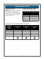
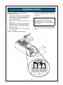
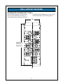
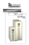
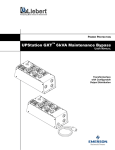
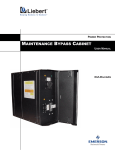
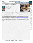
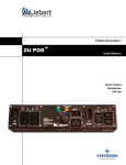
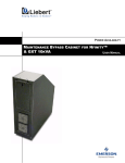
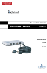
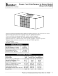
POWER PROTECTION
Configurable Output Distribution for GXT 6/10kVA
USER MANUAL
TABLE OF CONTENTS
IMPORTANT SAFETY INSTRUCTIONS . . . . . . . . . . . . . . . . . . . . . . . . . . . . . . . . . . . . . . . . . . 1
GLOSSARY OF SYMBOLS . . . . . . . . . . . . . . . . . . . . . . . . . . . . . . . . . . . . . . . . . . . . . . . . . . 2
GENERAL DESCRIPTION . . . . . . . . . . . . . . . . . . . . . . . . . . . . . . . . . . . . . . . . . . . . . . . . . . . 3
SYSTEM DESCRIPTION. . . . . . . . . . . . . . . . . . . . . . . . . . . . . . . . . . . . . . . . . . . . . . . . . . . . 3
Features . . . . . . . . . . . . . . . . . . . . . . . . . . . . . . . . . . . . . . . . . . . . . . . . . . . . . . . . . . . . . . . . . . . . . . 3
Standard Components . . . . . . . . . . . . . . . . . . . . . . . . . . . . . . . . . . . . . . . . . . . . . . . . . . . . . . . . . . . 3
Options . . . . . . . . . . . . . . . . . . . . . . . . . . . . . . . . . . . . . . . . . . . . . . . . . . . . . . . . . . . . . . . . . . . . . . . 3
MAJOR COMPONENTS . . . . . . . . . . . . . . . . . . . . . . . . . . . . . . . . . . . . . . . . . . . . . . . . . . . . 4
SELECTABLE OUTPUT DISTRIBUTION . . . . . . . . . . . . . . . . . . . . . . . . . . . . . . . . . . . . . . . 4
15 Amp Options . . . . . . . . . . . . . . . . . . . . . . . . . . . . . . . . . . . . . . . . . . . . . . . . . . . . . . . . . . . . . . . .
20 Amp Options . . . . . . . . . . . . . . . . . . . . . . . . . . . . . . . . . . . . . . . . . . . . . . . . . . . . . . . . . . . . . . . .
30 Amp Options . . . . . . . . . . . . . . . . . . . . . . . . . . . . . . . . . . . . . . . . . . . . . . . . . . . . . . . . . . . . . . . .
Other Options . . . . . . . . . . . . . . . . . . . . . . . . . . . . . . . . . . . . . . . . . . . . . . . . . . . . . . . . . . . . . . . . . .
4
4
4
4
CABLE INSTALLATION . . . . . . . . . . . . . . . . . . . . . . . . . . . . . . . . . . . . . . . . . . . . . . . . . . . . 5
WIRING PREPARATION . . . . . . . . . . . . . . . . . . . . . . . . . . . . . . . . . . . . . . . . . . . . . . . . . . . . 5
POWER CABLE INSTALLATION . . . . . . . . . . . . . . . . . . . . . . . . . . . . . . . . . . . . . . . . . . . . . 5
Connecting Configurable Output Distribution Option to GXT 6kVA/10kVA . . . . . . . . . . . . . . . . . . . 5
HARDWIRE OPTION . . . . . . . . . . . . . . . . . . . . . . . . . . . . . . . . . . . . . . . . . . . . . . . . . . . . . . 6
WALL-MOUNT DIAGRAM . . . . . . . . . . . . . . . . . . . . . . . . . . . . . . . . . . . . . . . . . . . . . . . . . . 7
DIAGRAM FOR ATTACHING UNIT TO WALL . . . . . . . . . . . . . . . . . . . . . . . . . . . . . . . . . . . 7
i
IMPORTANT SAFETY INSTRUCTIONS
SAVE THESE INSTRUCTIONS
CAUTION: To reduce the risks of fire connect
This manual contains important instructions that
should be closely followed during installation and
maintenance of this Configurable Output
Distribution.
only to a circuit provided with maximum branch
circuit overcurrent protection of 65A according to
model in accordance with applicable national and
local electrical codes.
This product is designed for commercial / industrial
use only. This product is not intended for use with
life support and other designated “critical” devices.
Maximum load must not exceed that shown on the
UPS.
Operate the UPS equipment in an indoor
environment only in an ambient temperature range
of 32°F to 104°F (0°C to 40°C). Install it in a clean
environment, free from conductive contaminates,
moisture, flammable liquids, gases, or corrosive
substances.
WARNING: Lethal voltages may be present
within this unit even when it is apparently not
operating. Observe all cautions and warnings in
this manual. Failure to do so may result in serious
injury or death. Never work alone.
The UPStation GXT Configurable Output
Distribution unit is designed for use on properly
grounded (earthed) 120/208/240VAC 60Hz
supply, for installation by qualified personnel. This
UPS equipment is intended to be installed by a
qualified / certified electrician who must review and
approve customer supplied wiring, circuit
breakers, intended loads and verify correct input,
output and earth connections to ensure
compliance with technical standards and national
and local electrical codes. Installation instructions
and warning notices are in the Cable Installation
section of this manual.
1
GLOSSARY OF SYMBOLS
Risk of electrical shock
Indicates Caution followed by important instructions
AC input
AC output
i
Requests the user to consult the manual
Equipment grounding conductor
On
Off
2
GENERAL DESCRIPTION
Features
• Supports up to 10 kVA loads
• Compact design
• Highly configurable
• Multiple power path indicators
Congratulations on your purchase of Liebert's
UPStation GXT Configurable Output Distribution.
As with every Liebert product, we stand behind our
quality. If you have any questions concerning this
configurable distribution option, please feel free to
contact your local sales representative, or call the
appropriate Technical Support number listed in the
back of this manual.
Standard Components
• Provisions for hardwire output
• Power-on indicator lamps
• Branch rated circuit breakers
To ensure proper installation and operation of this
unit, please read this manual thoroughly.
While installation must be completed by a
qualified / certified electrician, general operation
may be performed without special training.
Options
• User selectable output distribution
SYSTEM DESCRIPTION
The Configurable Output Distribution was
designed to provide maximum flexibility to
business critical equipment.
Various output receptacle options are available
from 15 A to 30 A. Hardwire options are also
available with or without a branch rated circuit
breaker.
3
MAJOR COMPONENTS
The following is a general description of each
component and its functions. Please review this
section carefully, as it will give you a better
understanding as to how the UPStation GXT
Configurable Output Distribution operates.
20 Amp Options
5-20R2
L5-20R
L6-20R-208
L6-20R-240
SELECTABLE OUTPUT DISTRIBUTION
L14-20R-240
Several receptacle and hardwire options are
available as user selectable output distribution.
These are factory configured when ordered and
also allow for field upgrades. Common receptacle
and hardwire options include:
20A,120V,1 Pole Breaker w/ 1/2" & 3/4" knockouts
20A, 208V,2 Pole Breaker w/ 1/2" & 3/4" knockouts
20A, 240V,2 Pole Breaker w/ 1/2" & 3/4" knockouts
30 Amp Options
15 Amp Options
L5-30R
5-15R2
L6-30R-208
L5-15R2
L6-30R-240
6-15R2-208
L14-30R-240
6-15R2-240
30A,120V,1 Pole Breaker w/ 1/2" & 3/4" knockouts
L6-15R2-208
30A,208V,2 Pole Breaker w/ 1/2" & 3/4" knockouts
L6-15R2-240
30A,240V,2 Pole Breaker w/ 1/2" & 3/4" knockouts
15A,120V,1 Pole Breaker w/ 1/2" & 3/4" knockouts
15A,208V,2 Pole Breaker w/ 1/2" & 3/4" knockouts
Other Options
15A,240V,2 Pole Breaker w/ 1/2" & 3/4" knockouts
Single Position Blanking Plate
Hardwire Option
4
CABLE INSTALLATION
WIRING PREPARATION
POWER CABLE INSTALLATION
WARNING: Please read this section thoroughly
Refer to the charts below when selecting cables:
before attempting to install wiring to this unit.
Power Cable and Protection Ratings
Be sure that the unit is not connected to any AC
mains power source or UPS before installing any
wiring to this unit. This should be installed by a
qualified / certified electrician.
Part No.
PDX2...
Max Input Current
65 A
Input Protection
65 A
Max Output
Current
Input/ Output
Terminal Details
65 A
(32A @ 120V per leg)
8 AWG (8 mm2)
Size grounding (protective earth) conductors equal to circuit conductors
Connecting Configurable Output Distribution Option to GXT 6kVA/10kVA
Configurable
Output
Distribution
Wires
GXT6000/10000
208
1
GXT6000/10000
208X
GXT6000/10000
240X
L2A
L2
2
L2
L2
3
L1
L1
L1
N
N
4
GND
5
HARDWIRE OPTION
6. Connect the remaining wires in accordance
with the wiring diagram (located inside the end
cover plate).
This product is intended to be installed by a
qualified electrician only.
1. COMPLETELY REMOVE ALL POWER FROM
THE FRAME. If Configurable Output Distribution is connected to the UPS, disconnect
external battery supply.
2. Remove the end cover plate to access the terminal block.
3. Without disconnecting from the terminal block,
unscrew and pull out the hardwire plate(s).
4. Route all wires from the hardwire plate(s) to
the terminal block.
5. Connect the GROUND wire to the grounding
bar strip (GND3).
Figure 1
NOTE
When wiring 120 V loads, LINE must be
alternated between TB-1-1 and TB1-3 to
balance the 120 V load. Connect all neutral
wires to TB1-4
7. Replace the receptacle plates and the end
cover plate, using caution not to damage the
wires.
Accessing terminal block
240V
120V
208V
6
120V
WALL-MOUNT DIAGRAM
DIAGRAM FOR ATTACHING UNIT TO WALL
Use the following diagram, which shows the
location and measurements of factory-cut
mounting slots, when preparing to attach the
Configurable Output Distribution to a wall. Liebert
recommends using 1/4-20 mounting screws.
7.00
7.00
PD1XX...28.38
28.38
PD1XX...
PD2XX...24.31
PD2X
X...24.3
1
20.25
PD3XX...
PD3XX...20.25
C
C
L
L
7
POWER PROTECTION
Configurable Output Distribution for GXT 6/10kVA
USER MANUAL
The Company Behind the Products
Technical Support
With over a million installations around the globe,
Liebert is the world leader in computer protection
systems. Since its founding in 1965, Liebert has
developed a complete range of support and
protection systems for sensitive electronics:
United States
1050 Dearborn Drive
P.O. Box 29186
Columbus, OH 43229
1-800-222-5877
Outside the United States
+614-888-0246
•
•
•
•
•
Environmental systems—close-control air
conditioning from 1 to 60 tons
Power conditioning and UPS with power
ranges from 300 VA to more than 1000 kVA
Integrated systems that provide both
environmental and power protection in a
single, flexible package
Monitoring and control—from systems of any
size or location, on-site or remote
Service and support through more than 100
service centers around the world and a 24/7
Customer Response Center
While every precaution has been taken to ensure
the accuracy and completeness of this literature,
Liebert Corporation assumes no responsibility and
disclaims all liability for damages resulting from
use of this information or for any errors or
omissions.
© 1994 Liebert Corporation
All rights reserved throughout the world.
Specifications subject to change without notice.
® Liebert and the Liebert logo are registered
trademarks of Liebert Corporation. All names
referred to are trademarks or registered
trademarks of their respective owners.
SL-23446 (9/01)
24 hours a day, 7 days a week
1-800-222-5877
3-Phase UPS
1-800-543-2778
Environmental Control
1-800-543-2778
Italy
Via Leonardo Da Vinci 8
Zona Industriale Tognana
35028 Piove Di Sacco (PD)
+39 049 9719 111
FAX: +39 049 5841 257
Asia
23F, Allied Kajima Bldg.
138 Gloucester Road
Wanchai
Hong Kong
+852 2 572 2201
FAX: +852 2 831 0114
Web Site
www.liebert.com