1
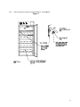
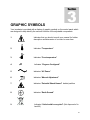
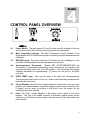
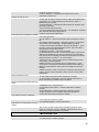
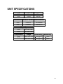
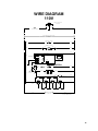
REACH-IN INCUBATOR
MODEL: RI28/RI40
01/11
4861573
INSTALLATION AND OPERATIONAL MANUAL
Sheldon Manufacturing Inc. P.O. Box 627 Cornelius, Oregon 97113
EMAIL: [email protected] INTERNET: http://www.Shellab.com/~Shellab
1-800-322-4897
(503) 640-3000
FAX (503) 640-1366
TABLE OF CONTENTS
SECTION 1.0
RECEIVING AND INSPECTION
SECTION 2.0
INSTALLATION
SECTION 3.0
GRAPHIC SYMBOLS
SECTION 4.0
CONTROL OVERVIEW
SECTION 5.0
OPERATION
SECTION 6.0
CHART RECORDER INSTALLATION
SECTION 7.0
MAINTENANCE
SECTION 8.0
TROUBLESHOOTING
SECTION 9.0
PARTS LIST
UNIT SPECIFICATIONS
SCHEMATICS
These units are general purpose incubators for professional, industrial or educational
use where the preparation or testing of materials is done at approximately atmospheric
pressure and no flammable, volatile or combustible materials are being heated. These
units are not intended for hazardous or household locations or use.
2
1
Section
RECEIVING AND INSPECTION
Your satisfaction and safety require a complete understanding of this unit. Read
the instructions thoroughly and be sure all operators are given adequate training
before attempting to put the unit in service. NOTE: This equipment must be used
only for its intended application; any alterations or modifications will VOID your
warranty.
1.1
Inspection: The carrier, when accepting shipment, also accepts responsibility
for safe delivery and is liable for loss or damage. On delivery, inspect for visible
exterior damage, note and describe on the freight bill any damage found, and
enter your claim on the form supplied by the carrier.
1.2
Inspect for concealed loss or damage on the unit itself, both interior and exterior.
If necessary, the carrier will arrange for official inspection to substantiate your
claim.
1.3
Return Shipment: Save the shipping crate until you are sure all is well. If for
any reason you must return the unit, first contact your customer representative
for authorization. Supply nameplate data, including model number and serial
number. Please see the manual cover for information on where to contact
customer service.
1.4
Accessories: Verify that all of the equipment indicated on the packing slip is
included with the unit. Carefully check all packaging before discarding. These
units are equipped with 6 shelves, 24 shelf clips and 4 leveling feet.
3
2
Section
INSTALLATION
Local city, county or other ordinances may govern the use of this equipment. If you have any questions
about local requirements, please contact the appropriate local agency. Installation may be performed by
the end user.
Under normal circumstances this unit is intended for use indoors, at room temperatures between 5 and
40 C, at no greater than 80% Relative Humidity (at 25 C) and with a supply voltage that does not vary by
more than 10%. Customer service should be contacted for operating conditions outside of these limits.
2.1
Power Source: The electrical supply circuit to the incubator must conform to all national and
local electrical codes. Consult the incubator’s serial data plate for the voltage and ampere
requirements before making connection. VOLTAGE SHOULD NOT VARY MORE THAN 10%
FROM THE SERIAL PLATE RATING. This unit is intended for 50/60 Hz application. A separate
circuit is recommended to prevent possible loss of product due to overloading or failure of other
equipment on the same circuit.
2.2
Location: When selecting a site for the incubator, consider all conditions which may affect
performance, such as extreme heat from steam radiators, stoves, ovens autoclaves, etc. Avoid
direct sun, fast-moving air currents, heating/cooling ducts, and high traffic areas. To ensure air
circulation around the unit allow a minimum of 10cm between the unit and any walls or partitions
which might obstruct free airflow.
2.3
Lifting / Handling: These units are heavy and care should be taken to use appropriate lifting
devices that are sufficiently rated for these loads. Units should only be lifted from their bottom
surfaces. Doors, handles and knobs are not adequate for lifting or stabilization. The unit should
be completely restrained from tipping during lifting or transport. All moving parts, such as shelves
and trays should be removed and doors need to be positively locked in the closed position during
transfer to prevent shifting and damage.
2.4
Leveling: The unit must sit level and solidly. Leveling feet (supplied) are to be installed in the
holes at the base of the incubator. Turn the leveling feet counterclockwise to raise level. If the
unit must be moved, turn the leveling feet in all the way to prevent bending of the feet.
2.5
Cleaning: The incubator was cleaned at the factory, but not sterilized. Remove all interior parts,
including shelves and shelf clips and clean all parts and the chamber with a disinfectant that is
appropriate for your application. A thorough periodic cleaning is strongly recommended.
WARNING: Never clean the unit with alcohol or flammable cleaners with the unit connected to the
electrical supply. Always disconnect the unit from the electrical service when cleaning and assure
all volatile or flammable cleaners are evaporated and dry before reattaching the unit to the power
supply.
4
2.6
Place shelves into chamber at desired position. See Figure 1.
Figure 1
5
3
Section
GRAPHIC SYMBOLS
Your incubator is provided with a display of graphic symbols on the control panel which
are designed to help identify the use and function of the adjustable components.
1.
Indicates that you should consult your manual for further
description and discussion of a control or user item.
2.
Indicates “Temperature”
3.
Indicates “Overtemperature”
4.
C
Indicates “Degrees Centigrade”
5.
Indicates “AC Power”
6.
Indicates “Manual Adjustment”
7.
Indicates “Potential Shock Hazard” behind partition
8.
Indicates “Earth Ground”
9.
Indicates “Unit should be recycled” (Not disposed of in
land-fill)
6
4
Section
CONTROL PANEL OVERVIEW
4.1
Power Switch: The main power I/O (on/off) switch controls all power to the unit
and must be in the I/ON position before any systems are operational.
4.2
Main Temperature Control: The Main Temperature Control consists of the
digital display and UP/DOWN arrow pads for inputting set point temperatures and
calibration.
4.3
HEATING Lamp: This green pilot lamp in ON when the unit is heating up to set
point and is blinking when controlling temperature at set point.
4.4
Overtemperature Thermostat:
Marked SET OVERTEMPERATURE, the
Thermostat is a completely independent control that acts as an override in the
event that the Main control fails in the ON position. The Thermostat will regulate
chamber temperature at approximately 1 C above the set point of the Main
controller.
4.5
OVER TEMP Lamp: This red pilot lamp is On when the Overtemperature
Thermostat has taken control of the unit. Under normal operating conditions this
lamp should never be on.
4.6
Circuit Breaker: (Non-CE units) Located adjacent to the power cord, the circuit
breaker is an added measure of protection against power source variations that,
if tripped, can be reset by pushing in the button once the reason for the
interruption has been cleared.
4.7
Fuse: (CE units) Located adjacent to the power cord in place of the circuit
breaker. The fuse is an added measure of protection against power source
variations, and if blown must be replace once the source of the interruption has
been cleared.
7
5
Section
OPERATION
5.1
Check power supply against unit data plate, they must match. Plug service cord into the
grounded electrical outlet, and turn the unit on.
5.2
Turn the Overtemperature Thermostat to its maximum position, clockwise, using a coin
or a flat edged tool.
5.3
There are four (4) electrical outlets inside the chamber for use with electrical equipment
not exceeding 1 amp.
5.4
Operating Electrical Apparatus Inside Chamber: Place the shaker, roller, spinner,
etc. inside the incubator chamber. Plug apparatus into 1 amp outlet at rear of chamber.
Be sure apparatus draws 1 amp or less (the power switch turns power on & off to outlets
inside chamber).
5.5
Set Main Temperature Controller: Enter desired set point temperature. To enter set
point mode on the controller, press either the Up or Down arrow pad one time. The
digital display will start to blink, going from bright to dim. While blinking, the digital
display is showing the set point. To change the set point, use the Up and Down arrow
pads. If the arrow pads are not pressed for five (5) seconds, the display will stop
blinking and will read the chamber temperature. Note that the Overtemperature
Thermostat should be turned to its maximum position, (clockwise) until the unit has
stabilized at desired set point temperature. Allow the incubator at least 24 hours to
stabilize.
5.6
Calibration: It is recommended that calibration is done once the unit is installed in its
working environment and has been stabile at set point for several hours. Place a
certified reference thermometer in the chamber where it can be easily viewed through
the window. Be certain the thermometer is not touching any shelving. Allow the
temperature to stabilize again until the thermometer reads a constant value for one hour.
Compare the digital display with the reference thermometer. If there is an unacceptable
difference, put the display into calibration mode by pressing both the Up and Down
arrow pads at the same time for five (5) seconds until the two outside decimal points
begin to flash. While the decimal points are flashing the display can be calibrated by
pressing the Up or Down arrow pads until the display reads the correct value. Allow the
incubator temperature to stabilize again, and recalibrate if necessary.
5.7
Set Overtemperature Thermostat: As mentioned in step 5.2, the Overtemperature
Thermostat should be initially set to its maximum position, to allow the unit to stabilize.
Once the incubator is stabile at the desired set point, turn the Thermostat
counterclockwise until the OVER TEMP light turns on. Next, turn the Thermostat
clockwise just until the light turns off. Then turn the Thermostat clockwise two of the
smallest divisions on its scale past the point where the light went out. This will set the
Overtemperature Thermostat at approximately 1 C above Main temperature set point.
8
6
Section
CHART RECORDER INSTALLATION
Please note that the following information is a general guide for installation.
Chart recorders are available from your dealer. Before attempting installation
please read the instructions provided with your chart recorder thoroughly for
specific installation instructions. Note: Unplug unit from the power supply before
installing the Chart Recorder.
6.1
Remove cover for Chart Recorder, located on the right side of control panel.
6.2
Remove steel plate from the back of the Chart Recorder.
6.3
Open the front glass door on the Chart Recorder and loosen the two screws on
the face of the recorder. (Screws are on the top and bottom right of the face.)
6.4
Inside the unit, behind the cover plate, you will see two wires that say “Recorder
Power”. Cut off the butt connectors and strip the wires about 3/8 inch.
6.5
Put the Recorder Power wires through the hole in back of your Chart Recorder
and connect the Recorder power wires to the terminal inside.
6.6
Run the Chart Recorder probe through the probe hole and slide into probe clips
provided inside the chamber of the unit.
6.7
Inside the Chart Recorder you will see a piece of masking tape and a metal clip;
remove these; screw face bolts back in; screw in Chart Recorder; shut the glass
door on the Chart Recorder; plug unit into power supply; then turn on the unit.
6.8
In moving or mounting a chart, the pen arm and stylus must be raised by
pressing on the tab at the uppermost end of the arm. Even if the recorder is not
to be used, a fresh chart should be mounted or some sort of padding placed
under the stylus to protect the sapphire tip.
6.9
To remove and replace a chart, unscrew the hub knob and swing it 90
clockwise, or to the 3 o’clock position. Press the upper tab on the pen arm; lift
the chart forward off the hub and slide down and away. DO NOT release the pen
arm, but install a new chart.
6.10
Now the pen arm may be gently released and the chart knob rotated
counterclockwise back to the hub. Align the proper chart time with the chart plate
index.
9
7
Section
MAINTENANCE
NOTE: Disconnect the power cord from the power source before performing any
service or maintenance on this unit.
7.1
Cleaning: Clean the incubator interior and remove and clean shelves on a
regular basis. Use a disinfectant that is suitable for your application. A thorough
periodic cleaning is strongly recommended. Use care when cleaning the door
gasket to prevent damage which could impair the positive door seal.
WARNING: Never clean the unit with alcohol or flammable cleaners with the unit
connected to the electrical supply. Always disconnect the unit from the electrical
service when cleaning and assure all volatile or flammable cleaners are
evaporated and dry before reattaching the unit to the power supply.
7.2
Storage: To prepare the unit for storage, remove all shelves and shelf clips and
disconnect the power supply. Be certain that the chamber is clean and dry and
the door is positively locked in the closed position.
See Section 2.3,
Lifting/Handling, for proper transport procedures.
7.3
No maintenance is required on the electrical components. If electrical or
temperature problems occur, please see the Troubleshooting guide, Section 8.0,
before calling for service.
10
8
Section
TROUBLESHOOTING
FOR PERSONAL SAFETY, ALWAYS DISCONNECT THE POWER BEFORE
SERVICING.
Always make a visual inspection of the incubator and control panel when
troubleshooting. Look for loose or disconnected wires that may be the source of
trouble.
TEMPERATURE
Temperature too high-display and
reference thermometer don’t match
1/ Controller set too high-see section 5.5.
2/ Controller failed on – call Customer Service.
3/ Wiring error – call Customer Service.
Display reads "HI" or "400"+
Probe is unplugged, is broken or wire to sensor is broken – trace wire
from display to probe; move wire and watch display to see intermittent
problems.
Chamber temperature spikes over set
point and then settles to set point
Recalibrate – see section 5.6.
Temperature too low-display and
reference thermometer don’t match
1/ High limit set too low - see section 5.7
2/ Controller set too low – see section 5.5.
3/ Unit not recovered from door opening – wait for display to stop
changing.
4/ Unit not recovered from power failure or being turned off – incubators
will need 24 hours to warm up and stabilize.
5/ Element failure – see if HEATING light is on; compare current draw to
data plate.
6/ Controller failure – confirm with front panel lights that controller is
calling for heat.
7/ Overtemperature failure – confirm with front panel lights that
Thermostat is operating correctly.
8/ Wiring problem – check all functions and compare wiring to owner’s
manual – especially around any areas recently worked on.
9/ Loose connection – call Customer Service.
Display reads "LO"
1/ If ambient temperature is lower than range of unit – compare set
points and ambient temperature to rated specifications in section 9.0.
2/ Sensor is plugged in backwards – call Customer Service.
Unit will not heat over a temperature that
is below set point
1/ Confirm that fan moving and that amperage and voltage match data
plate – check fan motor motion by removing top panel of the unit.
2/ Confirm that set point is set high enough –turn Thermostat all the way
clockwise and see if HEATING light or OVERTEMP light comes on.
11
3/ Check connections to sensor.
4/ Check calibration – using independent thermometer, follow
instructions in section 5.6.
Unit will not heat up at all
1/ Verify that controller is asking for heat by looking for HEATING light –
if pilot light is not on continuously during initial start up, there is a
problem with the controller.
2/ Check amperage – amperage should be virtually at maximum rated
(data plate) amperage.
3/ Do all controller functions work?
4/ Is the Overtemperature set high enough? – for diagnostics, should be
fully clockwise with the pilot light never on.
5/ Has the fuse/circuit breaker blown?
Indicated chamber temperature unstable
1/ ±0.1 may be normal.
2/ Is fan working? – remove top panel and verify movement of cooling
fan.
3/ Is ambient radically changing – either door opening or room airflow
from heaters or air conditioning? – stabilize ambient conditions.
4/ Sensor miss-located, damaged or wires may be damaged - check
mounts for control and Overtemperature sensors, then trace wires or
tubing between sensors and controls.
5/ Calibration sensitivity – call Customer Service.
6/ Overtemperature set too low – be sure that its setting is more than 5
degrees over desired set point; check if pilot light is on continuously;
turn controller knob completely clockwise to see if problem solved then
follow instructions in section 5.7 for correct setting.
7/ Electrical noise – remove nearby sources of RFI including motors,
arcing relays or radio transmitters.
8/ Bad connection on temperature sensor or faulty sensor – check
connectors for continuity and mechanical soundness while watching
display for erratic behavior; check sensor and wiring for mechanical
damage.
9/ Bad connections– check connectors for mechanical soundness and
look for corrosion around terminals or signs of arcing or other visible
deterioration.
Will not maintain set point
1/ Assure that set point is at least 5 degrees over ambient.
2/ See if ambient is fluctuating – check for adjacent open doors or
HVAC duct openings, stabilize ambient conditions.
Display and reference thermometer don’t
match
1/ Calibration error – see section 5.6.
2/ Temperature sensor failure – evaluate if pilot light is operating
correctly.
3/ Controller failure – evaluate if pilot light is operating correctly.
4/ Allow at least 24 hours to stabilize at set point temperature.
5/ Verify that reference thermometer is certified.
Can't adjust set points or calibration
1/ Turn entire unit off and on to reset.
2/ If repeatedly happens, call Customer Service.
Calibrated at one temperature, but not at
another
This can be a normal condition when operating temperature varies
widely. For maximum accuracy, calibration should be done at or as
close to the set point temperature as possible.
MECHANICAL
Door not sealing
1/ Check physical condition of gasket.
12
2/ Assure that gasket is in original location.
3/ Adjust hinge blocks or twist the door.
4/ Confirm that unit has not been damaged and body is square.
Motor doesn't move
1/ If shaft spins freely: check connections to motor and check voltage to
motor.
2/ If shaft rubs or is frozen, relieve binding and retest.
Motor makes noise
1) Make sure that the fan or blower wheel is not contacting its housing.
Adjust the motor mounting bracket position to re-center the fan or
blower wheel, if necessary.
2) Check the fan or blower wheel for damage or out of balance
condition. Replace the fan or blower wheel if it is damaged or out of
balance.
3) Turn the motor shaft to make sure that it spins freely. If it binds or the
bearings make a rubbing or scrapping sound then replace the motor.
OTHER
Controller on at all times - "locked-up"
1/ Turn unit off and on to reset.
2/ If cannot change any condition on the front panel, call Customer
Service.
Front panel displays are all off
Check for wire damage.
Unit or wall fuse/circuit breaker is blown
1/ Check wall power source.
2/ Compare current draw and compare to specs on data plate.
3/ See what other loads are on the wall circuit.
Unit will not turn on
1/ Check wall power source.
2/ Check fuse/circuit breaker on unit or in wall.
3/ See if unit is on, e.g., fan or heater, and just controller is off.
4/ Check all wiring connections, especially around the on/off switch.
Unit is smoking – Out of box
This is not an uncommon occurrence when first operating new units.
Put unit under vent and run at full power for one hour. – smoking is
normal during first cycle to temperature.
Contamination in chamber
1/ See cleaning procedure in section 2.5.
2/ Develop and follow standard operating procedure for specific
application; include definition of cleaning technique and maintenance
schedule.
If following these troubleshooting suggestions does not solve the problem call your customer service
representative for assistance. Please see the manual cover for information on where to contact customer
service.
13
9
Section
PARTS LIST
Description
Blower Motor
Blower Wheel
Circuit Breaker
Cooling Fan, Control Panel
Cord Set
Cord set, European
EMI Filter, CE units only
Fuse 10 Amp (RI28-2)
Fuse 16 Amp (RI40-2)
Heating Element, RI28
Heating Element, RI40
Overtemperature Thermostat
I/O (On/Off) Power Switch
Moisture Proof Plug
Main Control w/Sensing Probe
Outlet, Interior
Pilot Light, Green
Pilot Light, Red
Shelf, RI28
Shelf, RI40
115V
4880548
2600535
1100505
4880564
1800529
N/A
N/A
N/A
2350563
2350557
1750862
7850579
1650530
1750582
1650531
4650554
4650553
5400500
5401146
220V
4880548
2600535
N/A
4880563
1800537
1800541
2800502
3300516
3300513
2350554
2350566
1750813
7850579
1650530
1750583
1650531
4650554
4650553
5400500
5401146
14
UNIT SPECIFICATIONS
Weight
Shipping
Net
RI28
610 lbs.
500 lbs.
RI40
730 lbs.
850 lbs.
Dimensions Exterior WxDxH Interior WxDxH
RI28
37x33x75
30.5x26x62
RI40
41x34x87
35x26x76.5
Capacity
RI28
28 Cubic Feet
RI40
40 Cubic Feet
Temperature
Range
Uniformity
Sensitivity
RI28
Amb. +8 to 70 C
+ .5 C @ 37
+ .05 C
RI40
Amb. +8 to 70 C
+ .5 C @ 37
+ .05 C
15
WIRE DIAGRAM
110V
1800529 115V POWER CORD
HARD WIRED
WHT
BLK
1100505
CIRCUIT BREAKER 15A
BLK
WHT
MAIN POWER SWITCH CHERRY ROUND
7850532
BLK
WHT
POWER LIGHT ~ 200021 (G)
BLK
BLK
WHT
BLK
CHAMBER FAN ~ 4880548
BLK
RED
WHT
BLU
BLK
WHT
½ TB1
L1
½ TB1
L2
WHT
MICRO-A 1750582
BLK
HOT
37.0
NEUTRAL
PROBE
GROUND
LOAD
BLK
BLK
BLK
WHT
BLK
OTP LIGHT 200020 (R)
4
1
0900503
0.47 F / 250 VAC
BLK HT
2
OTP
10000J
WHT HT
ELEMENT ASSY 9570623
COIL P/N 210024
DESIGN = 750W / 120V / 19.2
BLK
BLK
WHT
BLK
HEAT LIGHT 200021 (G)
BLK
BLK
BLK
WHT
BLK
CONVENIENCE
OUTLETS
100020 x4
WHT
WHT
BLK
WHT
WHT
CHART RECORDER
CONNECTIONS
9851097
DL Robinson ~ R Benson 02/15/10
rev
16
WIRE DIAGRAM
220V Euro
3300516 / 10A / “T”
IEC FUSED INLET
4200505
WHT
3300501
FUSE
HOLDER
3300516
10A “T”
BLK
WHT
2800502
WHT
BLK
MAIN POWER SWITCH CHERRY ROUND
7850532
BLK
WHT
POWER LIGHT ~ 200021 (G)
BLK
BLK
CHAMBER FAN ~ 4880548
RED
½ TB1
L1
WHT
½ TB1
L2
BLU & BLK
WHT
MICRO-A 1750583
BLK
HOT
37.0
NEUTRAL
PROBE
GROUND
LOAD
BLK
BLK
BLK
0900503
0.47 F / 250 VAC
4
1
OTP LIGHT 200020 (R)
4
BLK HT
2
½ OTP
1750813
WHT HT
ELEMENT ASSY 9570624
COIL P/N 120071
DESIGN = 750W / 250V / 83
BLK
BLK
2
1
WHT
½ OTP
1750813
HEAT LIGHT 200021 (G)
BLK
BLK
WHT
BLK
BLK
WHT
BLK
EURO OUTLETS
X1000779 x4
BLK
WHT
WHT
WHT
CHART RECORDER
CONNECTIONS
WHT
9851091
DL Robinson ~ R Benson
rev 02/15/10
17