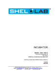
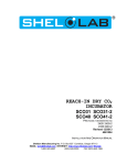
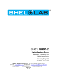
1
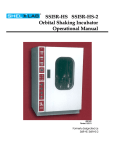
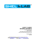
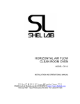
ECONOMY INCUBATOR SMI1EM SMI1EM-2 Previously designated as: EI1M EI1M-2 21/2013 4861654 INSTALLATION AND OPERATIONAL MANUAL Sheldon Manufacturing Inc. P.O. Box 627 Cornelius, Oregon 97113 EMAIL: [email protected] INTERNET: http://www.Shellab.com/~Shellab 1-800-322-4897 (503) 640-3000 FAX (503) 640-1366 TABLE OF CONTENTS SECTION 1.0 RECEIVING AND INSPECTION SECTION 2.0 GRAPHIC SYMBOLS SECTION 3.0 INSTALLATION SECTION 4.0 CONTROL PANEL OVERVIEW SECTION 5.0 OPERATION SECTION 6.0 MAINTENANCE SECTION 7.0 TROUBLESHOOTING SECTION 8.0 PARTS LIST UNIT SPECIFICATIONS SCHEMATICS These units are general purpose air incubators for professional, industrial or educational use where the preparation or testing of materials is done at approximately atmospheric pressure and no flammable, volatile or combustible materials are being heated. These units are not intended for hazardous or household locations or use. 1 Section RECEIVING AND INSPECTION Your satisfaction and safety require a complete understanding of this unit. Read the instructions thoroughly and be sure all operators are given adequate training before attempting to put the unit in service. NOTE: This equipment must be used only for its intended application; any alterations or modifications will void your warranty. 1.1 Inspection: The carrier, when accepting shipment, also accepts responsibility for safe delivery and is liable for loss or damage. On delivery, inspect for visible exterior damage, note and describe on the freight bill any damage found, and enter your claim on the form supplied by the carrier. 1.2 Inspect for concealed loss or damage on the unit itself, both interior and exterior. If necessary, the carrier will arrange for official inspection to substantiate your claim. 1.3 Return Shipment: Save the shipping crate until you are sure all is well. If for any reason you must return the unit, first contact your customer representative for authorization. Supply nameplate data, including model number and serial number. 1.4 Verify that all of the equipment indicated on the packing slip is included with the unit. Carefully check all packaging before discarding. These units are equipped with 2 shelves, 8 shelf clips, thermometer and thermometer clip. 2 Section GRAPHIC SYMBOLS Your incubator is provided with a display of graphic symbols to help in identifying the use and function of the available adjustable components. 2.1 This symbol, when shown, indicates that you should consult your manual for further description or discussion of a control or item. 2.2 Indicates “AC Power” 2.3 Indicates “Heating” 2.4 Indicates ”Adjustable Temperature” 2.5 Indicates “Manual Control” 2.6 Indicates “Earth Ground Symbol” 2.7 Indicates “Potential Shock Hazard” behind partition 2.8 Indicates “Unit should be recycled” (Not disposed of in land-fill 3 Section INSTALLATION Local city, county or other ordinances may govern the use of this equipment. If you have any questions about local requirements, please contact the appropriate local agency. Installation may be performed by the end user. Under normal circumstances this unit is intended for use indoors, at room temperatures between 5 above ambient to 70C, at no greater than 80% Relative Humidity (at 25C) and with a supply voltage that does not vary by more than 10%. Customer service should be contacted for operating conditions outside of these limits. 3.1 Power Source: The electrical supply circuit to the incubator must conform to all national and local electrical codes. Consult the incubator’s serial data plate for the voltage and ampere requirements before making connection. VOLTAGE SHOULD NOT VARY MORE THAN 10% FROM THE SERIAL PLATE RATING. This unit is intended for 50/60 Hz application. A separate circuit is recommended to prevent possible loss of product due to overloading or failure of other equipment on the same circuit. 3.2 Location: When selecting a site for the incubator, consider all conditions which may affect performance, such as extreme heat from steam radiators, stoves, ovens, autoclaves, etc. Avoid direct sun, fast-moving air currents, heating/cooling ducts, and high traffic areas. To ensure air circulation around the unit allow a minimum of 10cm between incubator rear and sides and any walls, partitions or obstructions to free airflow. 3.3 Lifting / Handling: These units are heavy and care should be taken to use appropriate lifting devices sufficiently rated for these loads. Units should only be lifted from their bottom surfaces. Doors, handles and knobs are not adequate for lifting or stabilization. The unit should be completely restrained from tipping during lifting or transport. All moving parts, such as shelves and trays should be removed and doors need to be positively locked in the closed position during transfer to prevent shifting and damage. 3.4 Leveling: The unit must sit level and solidly. The unit is equipped with non-adjustable rubber feet to raise it off the counter and prevent sliding; however, the counter must be level to provide optimum safety and working conditions. 3.5 Cleaning: The incubator interior was cleaned at the factory, but not sterilized. Remove all interior parts, including shelves and shelf clips if assembled. Clean with a disinfectant that is appropriate for your application. DO NOT USE spray cleaners that might leak through openings and cracks and get on electrical components, or that may contain solvents that will harm coatings. DO NOT USE chlorine-based bleaches or abrasives, as they will damage the stainless steel interior. Regular periodic cleaning is required. Special care should be taken when cleaning around sensing heads to prevent damage. WARNING: Never clean the unit with alcohol or flammable cleaners with the unit connected to the electrical supply. Always disconnect the unit from the electrical service when cleaning and assure all volatile or flammable cleaners are evaporated and dry before reattaching the unit to the power supply. 3.6 Shelf Placement: Place the two shelves in the desired position. See Figure 1. Figure 1 4 Section CONTROL PANEL OVERVIEW 4.1 Power Switch: The main power I/O (on/off) switch controls all power to the unit and must be in the I or ON position before any systems are operational. 4.2 Temperature Controller: This control is marked SET TEMPERATURE and consists of the digital display and Up/Down arrow pads for inputting set point temperature and calibration. 4.3 Circuit Breaker / Fuse: This control is adjacent to the power cord and provides protection for the unit’s electrical circuitry against power fluctuations. The circuit breaker, when tripped, must be reset by pushing in the extended button for the unit to continue operation. The fuse, when blown (on CE units in place of the circuit breaker) must be replaced before the unit can continue operation. 5 Section OPERATION 5.1 Check power supply against unit serial plate; they must match. Plug service cord into the grounded electrical outlet and turn the power switch ON. 5.2 Thermometer Placement: Place the thermometer and clip (provided in the accessory kit) through the hole at the top of incubator. The thermometer is to verify operating temperature. See Figure 3. 5.3 Set Temperature Controller: To set the main temperature controller, perform the following steps: 1. 2. 3. 4. 5.4 To enter set point mode on the controller, press either the UP or DOWN arrow pad one time. The digital display will start to blink, going from bright to dim. While blinking, the digital display is showing the set point. To change the set point, use the UP and DOWN arrow pads. If the arrow pads are not pressed in five (5) seconds, the display will stop blinking and will read the temperature of the unit. Allow the incubator at least 24 hours to stabilize. Calibrating the Main Temperature Control: We recommend that you calibrate your unit once it has been installed in its working environment and has been stable at the set point for 24 hours. To calibrate your unit, perform the following steps: 1. Place a certified reference thermometer in the chamber by placing it either directly inside or through the access tube at the top left of the unit. Ensure that the thermometer is not touching any shelving. If you place the thermometer directly inside the chamber, taping the thermometer to a Petri dish will raise it off the shelf and keep the scale in view. 2. Allow the temperature to stabilize again until the thermometer reads a constant value for one hour. 3. Compare the digital display with the reference thermometer. 4. If there is an unacceptable difference, put the display into calibration mode by pressing both the Up and Down arrow pads at the same time for approximately five (5) seconds until the display blinks off and on. 5. While blinking, the display can be calibrated by pressing the Up or Down arrow pads until the display reads the correct value. 6. Allow the incubator temperature to stabilize again, and recalibrate if necessary. Figure 3 6 Section MAINTENANCE NOTE: Prior to any maintenance or service on this unit, disconnect service cord from the power supply. 6.1 Cleaning: Clean interior of the incubator on a regular basis. Remove shelves and shelf clips and sterilize the incubator with a disinfectant that is appropriate for your application. The shelves and clips are autoclavable, or can be cleaned with the same solution as the incubator. DO NOT USE spray cleaners that might leak through openings and cracks and get on electrical components, or that may contain solvents that will harm coatings. DO NOT USE chlorine-based bleaches or abrasives, as they will damage the stainless steel interior. Regular periodic cleaning is required. Special care should be taken when cleaning around sensing heads to prevent damage. WARNING: Never clean the unit with alcohol or flammable cleaners with the unit connected to the electrical supply. Always disconnect the unit from the electrical service when cleaning and assure all volatile or flammable cleaners are evaporated and dry before reattaching the unit to the power supply. 6.2 When washing interior, handle the door gasket carefully so as not to impair the positive seal. 6.3 NO maintenance is required on the electrical components. If the incubator does not operate as specified, please see the Troubleshooting guide before calling for service. 7 Section TROUBLESHOOTING FOR PERSONAL SAFETY, ALWAYS DISCONNECT THE POWER BEFORE SERVICING. Always make a visual inspection of the incubator and control panel when troubleshooting. Look for loose or disconnected wires that may be the source of the trouble. TEMPERATURE Temperature too high 1/ controller set too high. 2/ controller failed on – call Customer Service Temperature too low 1/ controller set too low. 2/ unit not recovered from door opening – wait for heating indicator to turn off. 3/ unit not recovered from power failure or being turned off – incubators will need 2 hours to warm up and stabilize Unit will not heat over a temperature that is below set point Check calibration – using reference thermometer. Unit will not heat up at all 1/ verify that controller is asking for heat by looking for Heating indicator light – if pilot light is not on continuously during initial start-up, there is a problem with the controller. 2/ has the fuse/circuit breaker blown? Indicated chamber temperature unstable 1/ ±0.1 may be normal. 2/ is ambient radically changing – either door opening or room airflow from heaters or air conditioning? – stabilize ambient conditions. Will not maintain set point 1/ assure that set point is at least 5 degrees over ambient room temperature. MECHANICAL Door not sealing 1/ check physical condition of gasket 2/ assure that gasket is in original location 3/ Verify that door latch is operating correctly and not miss-aligned or broken. OTHER Unit or wall fuse/circuit breaker is blown 1/ check wall power source. 2/ see what other loads are on the wall circuit. 3/ has the circuit breaker on the front panel been tripped? Unit will not turn on 1/ check wall power source 2/ check fuse/circuit breaker on unit or in wall 3/ check all wiring connections, esp. around the on/off switch Unit is smoking – out of box This is not an uncommon occurrence when the protective coatings heat up during initial operation. Put unit under vent and run at full power for one hour until the smoke dissipates. Contamination in chamber 1/ see cleaning procedure. 2/ develop and follow standard operating procedure for specific application; include definition of cleaning technique and maintenance schedule. If following these troubleshooting suggestions does not solve the problem, call Customer Service for assistance. Please see the manual cover for information on where to contact Customer Service. 8 Section PARTS LIST Description 115V Circuit Breaker Heating Element I/O Switch Power Cord, USA Temperature Controller 1100505 2350562 7850570 1800529 1750549 UNIT SPECIFICATIONS Unit Dimensions WxDxH Exterior Interior SMI1EM & SMI1EM-2 16.75x17.75x22.25 (EI1M & EI1M-2) 12x12x14 Weight Net Shipping 53 lbs. 44 lbs. Capacity Cubic Ft Temperature C 1.0 Amb. +5-70 WIRE DIAGRAM SMI1EM (EI1M) (9851440) POWER CORD 1800529 CURCUIT BREAKER 1100505 GREEN LIGHTED SWITCH 7850570 WHITE HT SENSOR HOT NEUT RA L GROUND TEMPERATURE CONTROL 1750986 LOA D 2350562 120V 250W WIRE DIAGRAM SMI1EM-2 (EI1M-2) (9851441) POWER CORD 1800537 GREEN LIGHTED SWITCH 7850570 WHITE HT SENSOR HOT NEUTRAL GROUND TEMPERATURE CONTROL 1750987 LOAD 2350500 120V 125W 2350500 120V 125W