1
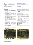
1.0 INTRODUCTION The RSR Electronics PLDT-3 digital logic trainer board, shown on cover page, has been designed as a "target board" for students and other users to design, implement, and test digital circuits using a modern programmable device and industry-standard design tools. It is built around the XILINX Corporation XC95108 CPLD device in an 84-pin PLCC package. While the fundamental principles of digital logic design have remained constant, the technology in which digital designs are implemented has changed rapidly. From transistors in the 1950s to small-scale integrated circuits (ICs) in the 1960s to large-scale ICs such as microprocessors in the 1970s, to the sophisticated programmable ICs of today Early digital IC devices, such as 7400 series TTL, were initially built as standard building-blocks that had to be interconnected by copper traces on a circuit board. By the 1980s, the blocks could be mounted on one chip, and the interconnection done by "burning" a design into it. Those were the early programmable logic devices (PALs, PLAs, PLDs). They were one-time programmable (OTP), and required an electronic "box" called a device programmer to do the "burning". Later came devices that could be erased electrically and reprogrammed. Today, ICs such as the venerable 7400 TTL chip are almost obsolete. Modern digital designs use large-scale programmable ICs such as field-programmable gate arrays (FPGAs) and complex programmable logic devices (CPLDs). Internally, FPGAs implement logic functions using look-up tables in memory blocks while CPLDs use sum-of-product terms configured from arrays of gates. Both FPGAs and CPLDs also contain flip-flops. To program such devices, special computer-aided design (CAD) software is required that allows the user to enter a digital design on a PC, check it for validity, simulate its performance, and then download it into the target chip. Depending on the CAD package being used, a design can be entered using schematic capture software to draw a diagram showing interconnected gate symbols. Or a design may be entered using a text editor to create a file containing a set of Boolean equations written in a hardware description language (HDL). A common HDL is ABEL (Advanced Boolean Expression Language). Either way, the CAD software compiles the design into the low-level commands needed to configure the device. The XC95108 CPLD contains 108 macrocells with 2400 usable gates arranged in six 36V18 function blocks as shown in Figure 1. The chip is available in speeds from 7.5 ns to 20 ns delay time pin-to-pin. Outputs can drive 24 mA loads. The XC95108 is rated for a minimum of 10,000 program/erase cycles, and will hold a program for a minimum of 20 years. 2