1
ProcessorTechnoiogy
16KRA
Dynamic Read/Write Memory Module
User's Manual
Processor Technology
Corporation
7100 Johnson Industrial Drive
Pleasanton, CA 94566
Telephone (415) 829-2600
Copyright 1977, 1978, by Processor Technology Corporation
Fourth Printing, April, 1978
Manual Part No. 730003
All rights reserved.
TABLE OF CONTENTS
PAGE
SECTION
1
2
INTRODUcrION AND GENERAL INFORMATION
1.1
Introduction. . . . . . . . . . . . . . . . . . . . . . . . . . . . . . . . . . . . . . . . . . . . . . . . . . . . . .
1-1
1.2
General Information
.
1-1
1.2.1
1.2.2
1.2.3
1.2.4
.
.
.
.
1-1
1-1
1-1
1-2
Handling Precautions . . . . . . . . . . . . . . . . . . . . . . . . . . . . . . . . . . . . . . . . . . . . . .
2-1
2.1.1
2.1.2
2.1.3
2.1.4
Installing and Removing the 16KRA . . . . . . . . . . . . . . . . . . . . . . . .
Handling MOS Integrated Circuits . . . . . . . . . . . . . . . . . . . . . . . . . .
Installing and Removing Integrated Circuits. . . . . . . . . . . . . . . . . .
Use of Qip Leads. . . . . . . . . . . . . . . . . . . . . . . . . . . . . . . . . . . . . . . .
2-1
2-1
2-1
2-1
Board Layout. . . . . . . . . . . . . . . . . . . . . . . . . . . . . . . . . . . . . . . . . . . . . . . . . . . . .
2-2
2.2.1
2.2.2
2-2
2-2
HANDLING PRECAUTIONS AND BOARD LAYOUT
2.1
2.2
3
4
5
16 KRA Memory Description
Receiving Inspection
Replacement Parts
Service
Orientation. . . . . . . . . . . . . . . . . . . . . . . . . . . . . . . . . . . . . . . . . . . . .
Layout. . . . . . . . . . . . . . . . . . . . . . . . . . . . . . . . . . . . . . . . . . . . . . . . .
OPERATIONAL TEST
3.1
16KRA Checkout Procedure..
3.2
Pre-operational Check.. . .. . . .
3.3
. . ..
. . . . . .. .
3-1
. . . . . . . . . .. . ..
3-1
Memory Test. . . . . . . . . . . . . . . . . . . . . . . . . . . . . . . . . . . . . . . . . . . . . . . . . . . . .
3-1
. . ..
.. . . ..
OPTION SELECTION
4.1
Option Selection. . . . . . . . . . . . . . . . . . . . . . . . . . . . . . . . . . . . . . . . . . . . . . . . . . .
4-1
4.2
Waiting Time Option (Area A).........
4-1
4.3
Power-up Initialization Option (Area B). . . . . . . . . . . . . . . . . . . . . . . . . . . . . . .
4-1
4.4
Memory Disable Option (Area C). . . .. .. . . . . . .. . .. . . .. . . . . . .. . .. .. . .. .
4-1
4.5
DMA Option (Area D)............................................ ..
4-1
4.6
Ready Line Option (Area E).........................................
4-2
4.7
Starting Address. . . . . . . . . . . . . . . . . . . . . . . . . . . . . . . . . . . . . . . . . . . . . . . . . . .
4-2
THEORY OF OPERATION
5.1
Overview. . . . . . . . . . . . . . . . . . . . . . . . . . . . . . . . . . . . . . . . . . . . . . . . . . . . . . . . .
5-1
5.2
S-l00 Bus Signals . . . . . . . . . . . . . . . . . . . . . . . . . . . . . . . . . . . . . . . . . . . . . . . . .
5-2
5.3
Detailed Description. . . . . . . . . . . . . . . . . . . . . . . . . . . . . . . . . . . . . . . . . . . . . . .
5-2
5.3.1
5.3.2
5.3.3
5.3.4
5-2
5-4
5-4
5-7
Page and Board Selection.. . . . .. . . . . . . . ..
. .. . . . ..
Memory Array and Drivers. . .. .... . .. . . ..
..
.. .. ... ..
Cycles
,....................................
Operations. . . . . . . . . . . . . . . . . . . . . . . . . . . . . . . . . . . . . . . . . . . . . .
18KRA
PAGE
SECTION
5.4
6
7
Refresh
"
" ..
5-9
l6KRA Assembly Drawing..........................................
6-1
l6KRA Schematic Diagram..........................................
6-2
l6KRA Block Diagram . . . . . . . . . . . . . . . . . . . . . . . . . . . . . . . . . . . . . . . . . . . . .
6-3
DRAWINGS
l6KRA DIAGNOSTIC TEST
7.1
Introduction
7.1.1
7.1.2
7.1.3
7.1.4
7.1.5
General
Data Path Test
Addressing Test
Exerciser
Numbered Test Selection
"
"
.
7-1
.
.
.
.
'" ..
7-1
7-1
7-1
7-2
7-2
7.2
Introduction to Test Procedure
.
7-2
7.3
Preliminary Testing
.
7-2
7.4
The l6KDT Test
.
7-4
7.5
Overview
.
7-4
Board Select
.
MC
.
SR
~
.
RC
.
CY
.
WE
.
AR
.
CAE
.
CAS ••........•..•........•......•..•.•.•.....•........
HAS
.
Output Enable
.
7-5
7-5
7.5.1
7.5.2
7.5.3
7.5.4
7.5.5
7.5.6
7.5.7
7.5.8
7.5.9
7.5.10
7.5.11
7-7
7-7
7-7
7-7
7-7
7-7
7-7
7-7
7-7
7.6
Bus Crashes
.
7-7
7.7
The RAM Chip
.
7-8
" ..
.
7-8
7-9
7.7.1
7.7.2
Overview
Troubleshooting the RAM
.
7-11
.
7-11
Machine Cycle - MC
.
7-11
7.11
Cycle Flip Flop - CY
.
7-12
7.12
Synchronous Refresh - SR
.
7-12
7.13
The Allow Refresh Flip Flop - AR
.
7-12
7.14
Page Selection
.
7-13
7.14.1
'7 14.2
.
.
7-13
7-13
7.8
The Write Request Flip Flop
7.9
Write Enable Operation - WE
7.10
'"
Overview
Troubleshooting the Page Select Circuit
II
18KRA
PAGE
SECTION
7.15
Ready Line
7.15.1
7.15.2
Queue Operation - QU
Troubleshooting the Ready Line
.
7-14
.
.
7-14
7-15
7.16
The Wait State Option
.
7-15
7.17
Refresh Cycle Flip Flop - RC
.
7-16
7.18
The Fresh Circuit
.
7-16
.
.
7-16
7-16
7.18.1
7.18.2
Overview
Troubleshooting Refresh
APPENDICES
1
IC Pin Configurations
2
Memory Test Program
TABLES
4-1
16KRA Starting Address Selection.. . . .. . . . . . .. . .. . . . . . . . . . . . . . . .. . . . .
4-3
5-1
Summary of S-I00 Bus Signals and Their Use.. . . . . . . . . . . . . . .. . . . . . . . . .
5-3
7-1
Test Addresses. . . . . . . . . . . . . . . . . . . . . . . . . . . . . . . . . . . . . . . . . . . . . . . . . . . .
7-2
7-2
Resistance Measurements at RAM Pins. . . . . . . . . . . . . . ... . . .. . . . . . . . . . . .
7-3
7-3
Bus Line-IC Pin Signal Checks. . . . .. . .. . . . . . . . .. . . . . . . . . . . . . . . . . . .. .
7-8
7-4
LS136 Pin Assignments. . . . . . . . . . . . . . . . . . . . . . . . . . . . . . . . . . . . . . . . . . . . .
7-14
7-5
Counter Periods. . . . . . . . . . . . . . . . . . . . . . . . . . . . . . . . . . . . . . . . . . . . . . . . . . .
7-16
FIGURES
2-1
Page and Bit Assignments in Memory Array . . . . . . . . . . . . . . . . . . . . . . . . . . .
2-3
4-1
Page and Address Line Assignments for Address Selection Switches. . . . . . . .
4-3
7-1
Connector Jumpers... . . . . .. . . .. . . . . . .. . . . . . . . . . . ... . . .. . . . . . . . . . . .
7-2
7-2
Address Switch Positions. . . . . . . . . . . . . . . . . . . . . . . . . . . . . . . . . . . . . . . . . . . .
7-4
7-3
16KRA Master Timing. . ... . . ... . . . . . . .. . . . .. . . . . . .. . .. . . .... . ... . .
7-6
7-4
RAM Chip Pin Assignments. . . . . . . . . . . . . . . . . . . . . . . . . . . . . . . . . . . . . . . . .
7-10
7-5
RAM Address Signal Waveforms. . . . . . . . . . . . . . . . . .... .
. . .. . . . .
7-10
7-6
Write Request (WR) Timing.. . . . . . . . . . . . . . . . . . . . .. .. . . .
..........
7-11
7-7
Cycle (CY) Timing. .. . . . . .. . . .. . . .. .. . . . . . . . . .. .. . . . . . . . . . . . . . . . . . .
7-12
7-8
MEMWRT Pulse Pattern. . . . . . . . . . . . . . . . . . . . . . . . . . . . . . . . . . . . . . . . . . . .
7-13
7-9
Refresh Page Selection Timing.. .. . . . . . . .. .. . .. .. . . . . . . . . . . . . .. .. . . . .
7-18
7-10
RAM Address Line Timing During Refresh. . . . . . . . . . . . . . . . . . . . . . . . . . . .
7-19
7-11
RAM Refresh Timing - Page 3 and 4 . . . . . . . . . . . . . . . . . . . . . . . . . . . . . . . . .
7-20
III
16KRA
I
I
I
I
I
I
I
I
I
I
I
I
I
I
I
I
I
I
I
I
I
I
I
I
I
I
I
I
I
I
I
I
I
I
I
I
I
I
I
I
I
I
I
I
I
I
I
I
I
I
I
I
SECTION
1
INTRODUCTION AND GENERAL INFORMATION
1.1 INTRODUCTION
This manual supplies the information needed to test and use the 16KRA Dynamic Read/Write Memory
Module. So that you can use your module most effectively and safely, we suggest that you read the entire
manual before attempting to use the 16KRA.
Should you encounter any problem in using the 16KRA, first consult the manual for a possible solution. If
you are unable to find the solution, feel free to ask for our help.
1.2 GENERAL INFORMATION
1.2.1 16KRAMemory Description
The 16KRA Dynamic ReadlWrite Memory Module has a capacity of 16,384 eight bit words and operates in a
dynamic mode. Periodic refreshing is done automatically by the module.
It is designed to operate in the Sol S-I00 bus and a number of other 8080-based computers such as the Altair
8800 and IMSAI 8080. Lines interfacing to the S-I00 bus are fully buffered, and extensive noise immunity
circuitry is used.
The 16KRA features switch selectable address selection. It is organized into four "pages" of 4096 bytes each.
Each page may be independently assigned to any of 16 starting addresses at 4096 byte intervals, starting with
address ()()()() (hexadecimal).
This module will operate in Sol and other 8080- based computers which have a 2 MHz ¢2 rate without
imposing wait states during normal operation. Access and cycle times are 400 and 520 nsec respectively.
The 16KRA Memory requires + 7.5 to + 10 V dc at 0.8 amp max., + 15 to + 18 V dc at .15 amp max., and
-15 to -18 V dc at .02 amp max. An on-board battery connector is also included for connecting standby power
to provide long term data retention during power loss.
The 16KRA board that you have received has several modifications made at the factory, shown on the
schematic and assembly drawing in Section 6, and covered in the text. Five jumper wires have been added to
the trace side of the board, all at ground potential, to improve ground return paths. Parts have been added
which insure that the timing of the Spontaneous Refresh Timer is within existing specifications, eliminating
possible harmless but unnecessary WAIT states.
1.2.2 Receiving Inspection
When your module arrives, examine the shipping container for signs of possible damage to the contents
during transit. Then inspect the contents for damage. (We suggest you save the shipping materials for use in
returning the module to your dealer, in case they need to ship it to the factory.) If your 16KRA is damaged,
please contact the carrier immediately, and write us describing the condition of both the shipping container
and its contents so that we can take appropriate action.
1.2.3 Replacement Parts
Order replacement parts by Processor Technology part number, component nomenclature (e.g., DM813l)
and/or a complete description (e.g., 6.8 ohm, 1/2 watt, 5% resistor). Your dealer may have a limited selection
of replacement parts on hand.
1-1
16KRA
1.2.4 service
Service on all Processor Technology equipment, in or out of warranty, is the responsibility of the selling
dealer. If you have difficulty in making your system work, or have subsequent failures that you cannot service
yourself, ask for your dealer's help.
1-2
16KRA
SECTION
2
HANDLING PRECAUTIONS
AND
BOARD LAYOUT
2.1 HANDLING PRECAUTIONS **IMPORTANT**
Though the 16KRA is already assembled and tested, you may have a future need to replace components
and/or make measurements on the board. Integrated circuits (IC's) can be damaged by improper handling.
Also, the module itself can be damaged by indiscriminate use of clip test leads as well as improperly installing
it in, or removing it from, the computer.
It is important, therefore, that you carefully read and observe the following precautions before testing or using
the 16KRA or replacing any IC.
2.1.1 Installing And Removing The 16KRA
To avoid any possible static electricity discharge damage to the MOS elements used on the 16KRA, always
place one hand on the computer chassis before touching the module and use your other hand for the module.
(just remember to handle the module so that no discharge flows through it and you'll do fine.) This precaution holds true whether you are installing or removing the 16KRA.
NEVER install the 16KRA in, or remove it from, the computer with the power on. To do so can damage the
module or the computer.
When installing the module, first make sure that you have it oriented correctly in relation to the bus pins.
That is, be sure that pin 1 on the module edge connector mates with pin 1 of the bus connector. (If you install
it reversed, you can damage the 16KRA or computer when power is turned on.) Slide module into card guides
until its edge connector just enters the bus connector. Then push on module until it is fully seated in the bus
connector.
2.1.2 Handling MOS Integrated Circuits
The memory IC's used on the 16KRA are MOS devices. They can be damaged by static electricity discharge.
Always handle MOS IC's so that no discharge will flow through the IC. Also, avoid unnecessary handling and
wear cotton-rather than synthetic-clothing when you do handle these IC's.
2.1.3 Installing And Removing Integrated Circuits
NEVER install or remove integrated circuits while power is applied to the 16KRA. To do so can damage the
IC.
2.1.4 Use of Clip Leads
Qip leads attached to the ends of the module are apt to short to IC pins.
Always attach ground clips to the lower edge of the board near edge connector pin 50 which is located at the
right end of the connector when the board is oriented as specified in Paragraph 2.2.1. (A terminal (wire) is
attached to pin 50 to provide a convenient grounding point.)
NOTE
The heat sink bar is a poor ground since its finish is nonconducting.
2-1
16KRA
2.2 BOARD LAYOUT
2.2.1 Orientation
With the component (front) side of the module facing up and the edge connector at the bottom, the heat sink
bar will be near the top edge of the circuit board. Subsequent position references in the next paragraph
assume this orientation. (See Assembly Drawing in Section 6, page 6-1.)
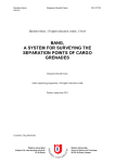
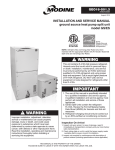
2.2.2 Layout
On the component side of the board, edge connector pin 1 is at the left end of the connector and pin 50 is at
the right end. Pins 51 and 100 are at the left and right ends respectively on the solder (back) side.
In the upper left comer are the address (page) selection switches. (See Section 4 for the page and address line
assignments for these switches.) Across the top half of the module is the memory array, two rows of 32
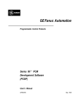
memory IC's separated in the middle by five drivers. Figure 2-1 shows the page and bit assignments for the
memory IC's. The heat sink bar runs across the board between the two rows of memory IC's.
Moving down to the lower half of the board you see all of the control logic for the 16KRA. In the lower left
comer is the battery backup power connector.
2-2
16KRA
TOP
UI
OF
U8
UII
I II PIg II P2g II PIg II P2g II PIg II P2g
PIg
U2
U3
U4
U5
U6
U7
PIg J P g
2
¥
w
IB~tIIB~tIIB~tIIB~tIIB~tIIB~tIIB~tllJ3~tl
U2I
BOARD
U22
g
P3 II P4g
U23
U24
U25
U26
U27
U28
II Pi II II II II II I
B~t IIB~t IIBi t
PZ
IIBi
t
P3g
PZ
P3g
P4g
IIB~t IIB~t IIB~t IIB~t
UI2
UI3
UI5
UI6
UI7
UI8
II P2g II PIg II P2g It Plil P2g II PIg II P2g
IB~t IIB~t IIB~t IIB~t IIB~tlIB~t IIB~t IIB~t
U32
U33
U34
U35
U36
U37
U38
U39
~m~m~m~~g
3
4
3
43·
4
3
4
B~t IIB~t IIB~t IIB~t IIB~t IIB~t IIB~t IIB~t
Figure 2-1. Page And Bit Assignments in Memory Array.
I
UI4
I
I
I
I
I
I
I
I
I
I
I
I
I
I
I
I
I
I
I
I
I
I
I
I
I
I
I
SECTION
3
OPERATIONAL TEST
3.1 16KRA CHECKOUT PROCEDURE
Your 16KRA Memory Module is fully inspected and tested before shipment to insure that it is operating
correctly and that it meets specifications. It is then packaged for safe transit under normal shipping conditions.
Your module should, therefore, arrive in your hands ready for use.
We nevertheless recommend that you precheck your 16KRA as outlined in the following paragraphs before
using it.
3.2 PRE-OPERATIONAL CHECK
Before installing the module in your computer, visually inspect it for obvious physical damage. Also check
that all integrated circuits (IC's) are fully seated in their sockets. If physical damage exists, follow the instructions given in Section 1, Paragraph 1.2.2. If your inspection reveals no problems, proceed with the memory
test.
3.3 MEMORY TEST
Install the 16KRA in your computer and test it for proper operation. Test programs and instructions for testing
the module are provided in Appendix 2.
CAUTION
NEVER INSTALL OR REMOVE 16KRA WITH COMPUTER
POWER ON.
3-1
18KRA
SECTION
4
OPTION SELECTION
4.1 OPTION SELECTION
Jumper options that control five operating parameters are provided on the 16KRA Memory Module. They are:
waiting time, power-up initialization, phantom memory disable, DMA waiting time, and ready line option. The
starting address for each page is switch-selectable. Use the following option selection instructions in conjunction with the assembly drawing in Section 6.
NOTE
We recommend you use #24 bare wire for jumpers. Simply bend
a small loop of wire and insert about 1/4 inch of wire into each
Augat pin.
4.2 WAITING TINE OPTION (AREA A)
Since the 16KRA operates at maximum speed, you normally will not enable the waitIng time option. To
configure the 16KRA for no waiting time, install a jumper between the Wand 0 pins in Area A.
For special applications, you may want to enable the waiting time option which provides one wait state that is
0.5 usec long. To enable the wait state, install a jumper between the Wand 1 pins in Area A.
4.3 POWER-UP INITIALIZATION OPTION (AREA B)
The jumper arrangement in Area B determines whether the 16KRA will come up in the protected or
unprotected mode when power is initially applied or restored after a power failure. In the protect mode a
random operation cannot improperly rewrite retained data.
To select the power-up protect mode, install a jumper between the CLR and P pins in Area B.
To select the power-up unprotect mode, install a jumper between the CLR and U pins in Area B.
NOTE
H your computer does not use the PROT (protect) and UNPROT
(unprotect) lines, PROT (S-I00 Bus pin 70) must be connected
to zero volts.
4.4 MEMORY DISABLE OPTION (AREA C)
Select the phantom option if the 16KRA will be used at address 0 in conjunction with a system which uses a
phantom start-up procedure, such as the Processor Technology Sol, GPM, or ALS-8 Firmware Module. To
enable this option, install a jumper between the two pins in Area C. With this jumper installed, the 16KRA
will be disabled by the signal PHANTOM, supplied on S-I00 pin 67.
H the 16KRA is not to be used at address 0, or is not to go in a system using phantom start-up, do not install
the jumper.
4.5 DMA OPTION (AREA D)
The jumper arrangement in Area D determines when the refresh timer (Ql and U63-8) is reset to zero. Two
options are available.
4-1
16KRA
The first, DN, is normally used. With this option selected, the refresh timer is reset to zero at every refresh
cycle. A DMA device which sends no read request for 6 usec will encounter a wait state while refresh is done.
With this option a DMA device must observe PRDY or be prepared to accept data errors if its requests are
coincident with spontaneous refresh. To select this option, install a jumper between the D and DN pins in
Area D.
If DR is enabled...
...the refresh timer is reset to zero after read and write cycles as well as after refresh cycles.
...a DMA device which sends a read or write request within 6 useconds will not encounter wait states.
.. .loss of refresh may occur on long DMA transfers that contain no read requests.
To enable this option, install a jumper between the D and DR pins in Area D.
DO NOT select this option unless it is absolutely necessary. If you do use this option, remember that
REFRESH IS THE RESPONSIBILITY OF THE DMA DEVICE. Check with us before using the DR option.
4.6 READY LINE OPTION (AREA E)
The 16KRA requires a wait period under certain unusual circumstances. The wait period is generated when
pin 23, Ready, of the 8080 microprocessor is pulled low. The Ready line is driven by S-loo bus signals XRDY
(pin 3) and PRDY (pin 72). Different computers require the use of one of these two signals with their
memory bOards. Consult the manual for your computer to determine which to use. (The Sol Terminal Computer uses PRDY.)
To select PRDY, jumper pin C to pin P in Area E.
To select XRDY, jumper pin C to pin X in Area E.
NOTE
Revision D and E 16KRA circuit boards are wired for the PRDY
option only. Connection to XRDY may be made by cutting a
trace and soldering a jumper in place.
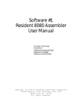
4.7 STARTING ADDRESS
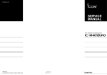
Each of the four 4096 byte pages in the 16KRA can be independently addressed with the dual inline (DIP)
switches located in the upper left corner of the module (board oriented as specified in Section 2). Page and
address line assignments for these switches are shown in Figure 4-1.
You can assign the same starting address to two, three or all four pages on one 16KRA module with no ill
effect.
In general, you may not assign any memory space to a 16KRA that is already assigned to another 16KRA
module-or any other memory module-if they are to share the same bus simultaneously. To do so will cause
the bus drivers to "fight" for possession of the bus which will result in improper operation or damage. (One
exception to this general rule is if you enable the phantom memory disable option which allows the ALS-8 to
share address zero with a 16KRA.)
To select the desired starting address for a page, set the four DIP switches associated with the page as shown
in Table 4-1. (Only the indicated starting addresses are available. No intermediate addresses can be used.)·
4-2
16KRA
Table 4-1. 16KRA Starting Address Selection.
STARTING ADDRESS
Decimal
DIP SWITCH SETTINGS
Hex
A15
A14
A13
A12
0
4,096
0000
X
X
X
X
1000
X
X
X
C
8,192
2000
X
X
C
X
12,288
16,384
3000
4000
X
X
C
C
X
C
X
X
20,480
5000
6000
X
C
X
C
X
X
C
C
X
7000
C
C
32,768
8000
C
X
X
X
36,864
9000
C
X
X
C
40,960
AOOO
C
X
C
X
45,056
BOOO
C
X
C
C
49,152
COOO
C
C
X
X
53,248
DOOO
C
C
X
C
57,344
EOOO
C
C
C
X
61,440
FOOO
C
C
C
C
24,576
28,672
X
C
=
=
C
switch open, or OFF (in down position)
switch closed, or ON (in up position)
A15 A14 A13 A12 A15 A14 A13 A12
SWl-8
0 0 D0 DD
Page 1
Page 3
SW2-8
Page 2
Page 4
0 0 0 0 D0
A15 A14 A13 A12 A15 A14A13 A12
SWl-l
fUPPER LEFT
OF
16KRA
CORNER
MODULE
SW2-1
I
Figure 4-1. Page and Address Line Assignments for
Address Selection Switches.
4-3
16KRA
SECTION
5
THEORY OF OPERATION
5.1 OVERVIEW
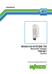
Refer to 16KRA schematic in Section 6, page 6-2, and 16KRA Block Diagram, page 6-3.
In the 16KRA a cycle is a timed sequence of events that perform one memory access. There are six kinds of
cycles-read, write, refresh, unselected, coincidence and null-and all are initiated by RC or MC. One or a
group of cycles intended to accomplish a desired result is called an "operation." A number of operation types
are possible in the 16KRA, but there are four intended operations: read, ready write, unready write and
spontaneous refresh. All other operations are variations of the intended operations and result from
asynchronou~ coincidence between intended operations.
Since the memory IC's (2104) used in the 16KRA are dynamic memories in which the data cells operate by
stored electrical charge, stored data must be read and restored periodically. Otherwise, current leakage would
eventually change the stored data. The restoring process is called "refreshing" the memory, or simply
"refresh."
The 16KRA provides memory refresh as required without any external intervention. In most cases it is done
without introducing any delay to the CPU or DMA device controlling the module.
Address lines A12-A15 are compared to four sets of four switches to select one or none of four 4K memory
arrays called "pages." Each page consists of eight 2104 memory IC's.
Address lines AO thru All are applied to a four-input multiplexer (U65-U67) in two groups of six. These two
groups are selected in succession to the memory address drivers (U10, U31, parts of U9, U29), which drive the
memory address inputs.
Row Address Strobe (HAS) is applied to the eight memory IC's of the selected page. Its leading edge causes
these eight IC's to store the first group of six address bits (AO-A5), called the row address, and start a memory
cycle.
Subsequently, column address strobe (CAS) is applied to all of the memory IC's. It causes them to release their
data outputs to the 3rd state (open circuited). Its leading edge causes those selected by HAS to store the second
group (A6-All), called the column address.
CAS samples Write Enable (WE) to determine whether this cycle is to write data into memory, or read data
from memory.
The contents of the Data Out Bus (DOO-OO7) are applied to the Data In pins of the memory array by eight
Memory Data drivers (U50, U5l). One bit from the Data Out bus is applied to four memory IC's, one in each
of the four pages.
In a memory write operation, CAS causes the selected eight memory IC's to store the data found on their Data
In pins in an input latch. This data is subsequently stored at the location described by the row and column
addresses.
In a memory read operation, the selected eight memory IC's receive data from the address indicated, send it to
their output latches, and enable their output drivers.
Shortly after the end of HAS and CAS, the read data is latched into the output register (U52, U53), and sent to
the Data In Bus (DIO-DI7) by the DI Bus Drivers (U68, U69) if these are enabled.
5-1
18KRA
Addressing is summarized here:
AO -A5
Selects Row inside memory chips
A6 -All
Selects Column inside memory chips
A12-A15
Selects one (or none) of four pages
and selects (or deselects) this board.
5.28-100 BUS SIGNALS
The host machine and l6KRA communicate with one another over the S-loo Bus. Table 5-1 identifies these
signals and their source and defines their function.
NOTE
The l6KRA ignores all S-loo Bus signals except those listed in
Table 5-1.
5.3 DETAILED DESCRIPTION
5.3.1 Page and Board selection
Page and board selection depends on address bits A12-A15 and on four groups of four switches.
Each group of four switches describes one of 16 possible starting addresses. Each group of four switches
corresponds to one page of eight memory Ie's.
The contents of each group of four switches is compared to address bits A12-A15 by four open collector
exclusive OR gates (U19, U20, U40, U4l). If a match is found, the (wire AND'ed) output line common to that
group of four is allowed to rise. These four lines are called match lines.
5-2
16KRA
Table 5-1. Summary of S-IOO Bus Signals And Their Use.
SIGNAL
SOURCE
FUNCTION
MEMWRT
Computer
Leading edge may initiate write operation.
PSYNC
Processor
Enables 02 trailing edge to request a Read cycle. PSYNC trailing edge
samples SMEMR and SWO to govern refresh.
~2
Computer
Trailing edge during SYNC or QU sets QU (deferred) if a cycle is in
process, or clears QU and starts a read cycle if no cycle is in process. It
also clocks wait binary.
D00-7
Processor
Data source for write operation.
AO-ll
Processor
Address source for memory array.
A12-15
Processor
Input source for page and board selection.
SINP
Processor
Inhibits hoard selection.
SOUT
Processor
Inhibits hoard selection.
SMEMR
Processor
Allows output data drivers to be enabled on read. Inhibits clocked
refresh during write operation.
SWO
Processor
Inhibits spontaneous refresh during write operation.
PDBIN
Processor
Allows output drivers to he enabled on read.
PWR
Processor
When high at leading edge of MEMWRT, indicates a front panel write
and requests a read so the front panel will display the new data.
PHANTOM
(optional)
Computer
Inhibits hoard selection.
PROT
Computer
Write protects 16KRA if high and hoard is selected. (Wire it low if
your machine doesn't provide it.)
UNPROT
Computer
Unprotects 16KRA if high and board is selected.
DlO-7
16KRA
Data delivered here after a read. Drivers are enabled by BOARD SELECT and PHANTOM and SMEMR and PDBIN.
PS
16KRA
Indicates selected board is write protected if low.
PRDY
16KRA
Indicates selected board is ready if high.
XRDY
16KRA
Alternate to PRDY.
5-3
16KRA
Each match line corresponds to a page. A one (high) on any match line causes those of higher page number to
be held at 0, thus only one page can be enabled (that with the lowest page number) even though more than
one switch set may match AI2-AI5. This feature allows the 16KRA board to be used in systems where less
than 16K is needed.
During memory cycles, the four match lines are selected by the multiplexer (U42) to drive the four PAGE
lines. The PAGE lines select one or none of four HAS drivers. The PAGE lines are or'ed together in pairs to
enable one or none of the two groups of six memory address drivers.
Only half of the address inputs of the memory array are driven at anyone time. This is done to reduce peak
current surges in the memory array.
A section of U60 forms the signal SINP+ SOUTo The four match lines are and'ed with this signal and OR'ed
together onto one line by U43 and appear at U44-8 as BOARD SELECf. BOARD SELECf • PHANTOM
enables the PS and PRDY drivers (U63-11).
U62-8 forms BOARD SELECf • SMEMR • PDBIN • PHANTOM which enables the DI Bus Drivers, sending
the contents of the ouput register to the DI Bus only during read operations when this board is selected.
The binary WR is clocked by the leading edge of MEMWRT. A low at WR will result in a WRITE operation.
WR can be clocked low only if this board is selected and not write protected. The gates at U70-3, U61-3 and
U63-8 provide the necessary signal at the K input of the binary WR.
5.3.2 Memory Array and DrIvers
The memory array consists of 32 2104 4K dynamic IC's arranged in four groups of eight. Each 2104 can store
4096 bits, and each group of eight stores 4096 bytes.
The 2104 is a 16 pin package. Four pins provide power (OV, + 5V, + 12V, -5V). One pin connects data in and
another connects data out. Six pins carry address data (12 bits in two six bit samples). The remaining four
pins control memory operation. HAS provides selection and timing, CAS provides timing, WE selects read or
write, and CS (chip select) is wired to OV (enabled) since selection is being done by HAS.
In the manufacturer's data some of these 12 signals are defined to be active low. (WE, CS, HAS, CAS). Others
are defined active high, but all are arbitrary (six Addresses, Data In, Data Out).
In the 16KRA Module, all 12 signals at the memory pins are defined to be active low.
All memory inputs on the 16KRA Module are driven by special memory drivers (seven packages of 75365's).
2104's are nominally TTL compatible, but better noise margins are achieved by using external drivers.
5.3.3 Cycl..
The timing of all six cycles (Read, Write, Refresh, Unselected, Coincidence and Null) is identical. Each consists
of a nominal 370 nsec active period and a nominal 150 nsec recovery period.
Either of two signals, MC or RC, can initiate a cycle. RC describes a refresh cycle and MC describes a read or
write cycle.
MC and RC are or'ed in U61, with the output on pin 8 being applied to U7l. U71 is a delay line with outputs
which reproduce MC+ RC delayed by 100 nsec (pin 14), 150 nsec (pin 4),250 nsec (pin 12) and 350 nsec (pin
6). This is a passive delay line consisting of LC sections and TTL drivers built into the input and output lines.
These four delayed outputs are connected to a four-input nand gate (U57-6), the output of which is used to
reset the binaries producing RC and MC. This reset will occur 350 nsec after the rise of RC or Me. RC+ MC
will then fall, and 100 nsec later U57-6 will rise again, releasing the resets of RC and MC.
The above cycle contains passive delays totaling 450 usee, and propagation delays through logic stages totaling
50 nsec min., 70 nsec typical. RC or MC will be on for about 370 nsec arid off for about 150 nsec, giving a
cycle duration of about 520 nsec.
Each cycle is described by the signal CY which is set to 1 at two propagation delays after the rise of MC+ RC,
and clocked to a 0 by the trailing (rising) edge of U57-6. Thus a cycle can be defined as the time during
which CY is on.
18KRA
MC+ RC causes RAS (row address strobe) at the selected page of memory IC's. The signal WE (write enable)
determines whether an MC is a read or a write. It controls the WE inputs to all memory IC's. The signal QU
describes a failed attempt to perform a memory cycle. Presence of QU requests that another attempt at a
memory cycle be made, and causes an unready (low on PRDY) if this board is selected.
The signal CAE (column address enable) is clocked to a I by the 100 nanosecond delay tap, only if MC is
high. Its presence causes the address multiplexer to present the second group of six address lines to the
memory address drivers. It is reset to 0 by the removal of MC+ RC.
The signal CAS (column address strobe) is clocked to a 1 by the 150 nsec delay tap, unless RC and MC are
both on. Its presence causes CAS to be applied to all memory IC's. It is reset to 0 by the same signal which
resets MC and RC.
In summary, a cycle starts with MC or RC. RAS comes on and samples the row address. At 100 nsec the
column address is presented. At 150 nsec CAS usually comes on, sampling the column address, write enable,
and the input data (DO Bus) if a write. At 350 nsec RAS and CAS are removed, and output data may be
clocked to the output register. At 520 nsec a new cycle may start.
Read Cycle
This normal cycle retrieves data from the indicated address. H SYNC or QU is present, the trailing edge of cP2
clocks MC to a 1 to start a cycle. RC remains at O. RAS occurs at the selected page of memory, causing the row
address to be saved, and starting a cycle within each of eight memory IC's. CY goes to 1.
After 100 nsec CAE is clocked to a 1. The column address is presented to the memory address drivers.
After 150 nsec, CAS is clocked to a 1. CAS occurs at all memory IC's, causing all to release their data output to
the third state. Within the eight memory IC's selected by RAS, the column address is saved, and WE is
sampled. This is a read cycle, so WE is high, and the input data is ignored. At some time before 350 nsec
from the start, each of the eight selected chips will enable its output pin which will contain valid data.
After 350 nsec, reset occurs and both MC and CAS become O. RAS is removed and CAE becomes O. Output
data is clocked to the output register and enabled to the DI Bus (if this board is selected, and SMEMR and
DBIN are high).
After 520 nsec, CY goes to 0 and a new cycle may start.
Write Cycle
This normal cycle stores data at the indicated address.
The signal WE becomes a 1. This causes MC to become a 1 to start a new cycle. RAS occurs at the selected
page of memory, causing the row address to be saved and starting a cycle within each of the eight selected
memory IC's. CY becomes a 1. RC remains at O.
After 100 nsec CAE is clocked to a 1. The column address is presented to the memory address drivers.
After 150 nsec CAS is clocked to a 1. CAS occurs at all memory IC's, causing all to release their data outputs
to the third state. Within the eight memory IC's selected by RAS, the column address is saved, and WE is
sampled. WE is found to be low. Sometime before 350 nsec, the input data will be stored at the indicated
address. At some other time before 350 nsec, the selected eight memory IC's will enable their outputs, and
present l's there.
After 350 nsec, reset occurs. MC, CAS, and WE become O. RAS is removed, CAE becomes O. Output data (all
1's) is clocked to the output register, but not enabled to the DI Bus since SMEMR and PDBIN are low.
After 520 nsec CY becomes a 0 and a new cycle may start.
Refresh Cycle
This normal cycle refreshes the data in one row in the eight memory IC's of one page. Since there are 64 rows
in each IC, and four pages on this board, a complete refresh will require 256 refresh cycles. The eight bit
refresh counter (U49, U64) indicates one of these 256 states.
RC becomes a 1. The address multiplexer selects the high order six bits of the refresh counter as the source of
address for the memory address drivers. The page multiplexer selects the four outputs of U58 as the source of
5·5
16KRA
data for the page lines (instead of the match lines). U58 enables one of four lines selected by the two least
significant bits of the refresh counter.
RAS occurs at the selected page of memory, causing the row address (from the refresh counter) to be saved,
and starting a cycle within each of the eight selected memory IC's. CY becomes a 1.
After 100 nsec CAE is clocked, but does not go to 1 since MC is low. The address multiplexer continues to
present the row address.
After 150 nsec, CAS is clocked to a 1. CAS occurs at all memory IC's, causing all to release their data outputs
to the third state. The column address is saved and WE is sampled and found to be high. Input data is
ignored. Before 350 nsec the data described (which is irrelevant) is presented at the outputs.
After 350 nsec, reset occurs. RC and CAS become O. HAS is removed, CAE is already 0, so CAE is high, and
the refresh counter counts 1. CAE, being high already, does not rise, so the output data is not clocked to the
output register. The output data remains the same.
After 520 nsec, CY becomes 0, and a new cycle may start.
To the Memory IC's selected, this seems to be a normal read cycle. They are designed to refresh all data
within a row each time that row is accessed by a HAS, regardless of the details of a cycle.
Unselected Cycle (CAS only cycle)
This normal cycle has no external purpose. It is the result of the method used to accomplish refresh.
If SYNC or QU is present, the trailing edge of cf>2 clocks MC to 1 to start a cycle. RC remains at O. The address
does not represent any page on this board, so no page is selected, and BOARD SELECT is low.
Since no page is selected, no memory chips receive RAS, none start a cycle.
After 100 nsec CAE is clocked to a 1. The column address is presented to the address drivers.
After 150 nsec, CAS is clocked to 1 and CAS occurs at all memory IC's, causing all to release their data
outputs to the third state. No memory IC's have been started by HAS, so no address storage and read occur.
WE is high, but isn't used anyway.
After 350 nsec, reset occurs, MC and CAS become O. CAE becomes O. The output pins are third state and this
indeterminate data is clocked to the output register destroying the previous data. The output does not get
enabled to the DI Bus because this board is not selected.
After 520 nsec, CY goes to 0, and a new cycle may start.
Coincidence Cycle
This is an abnormal cycle which occurs when two asynchronous requests for memory occur at times such as to
set both RC and MC to 1 at approximately the same time.
Normally RC and MC do not both occur in one cycle, since the presence of each is intended to prevent the
other. Due to propagation delays, it is impossible to make them totally mutually exclusive, however, it is
guaranteed that if both are to occur, the second will follow the first by only a few stage delays (typically less
than 50 nsec). The COINCIDENCE CYCLE is an example of this.
RC or MC occurs. Before inhibition is complete the other of RC or MC occurs. Subsequent events in the cycle
are timed by the first of the two. WE may be in either state.
HAS occurs at the selected page of memory, causing the row address to be saved and starting cycles in these
eight memory IC's. Shortly after both RC and MC = 1, RC • MC becomes a O. This signal forces QU to 1,
indicating a failed attempt and and a request for a new attempt. QU causes PRDYto go low since this board is
selected.
After 100 nsec, CAE is clocked to a 1 and column address 0 is presented to the memory drivers.
After 150 nsec, CAS is clocked, but it does not go to 1 since its J input (MC • RC) is low. No CAS occurs. The
memory IC's selected by HAS execute a HAS only cycle. This refreshes some row of memory and has no
consequences external to the memory IC's. WE does not get sampled, and no memory chips change the state of
their outputs.
5-6
16KRA
After 350 nsee, reset occurs. MC, RC become O. RAS is removed. Since CAE is low, the refresh counter does
not advance. (Coincidence cycle is not counted as a good refresh.) CAE is reset to 0, clocking unknown data
into the output register which is enabled to the DI Bus. (The processor or DMA device must observe the low
on the PRDY line. This is bad data.)
After 520 nsee, CY goes to 0 and a new cycle may start. Note that if the coincidence cycle started at a 4>2
trailing edge, then the next 4>2 trailing edge has already occurred. In this case, QU remains set and the next
subsequent 4>2 trailing edge will start a new cycle. Thus a coincidence cycle may cause two consecutive wait
states.
Null Cycle
The NULL Cycle is a coincidence cycle which is also an unselected cycle.
Both RC and MC occur at approximately the same time. The address does not represent any page on this
board, so all four match lines, and BOARD SELECT are low. The row address chosen is the refresh address, so
one page line (from the refresh counter via U58) is high. RAS occurs at the selected eight memory IC's,
causing each to store the row address and start a memory cycle. Shortly after MC and RC become a I, MC •
RC becomes a 0, and sets QU to a I, indicating a failed attempt and a request for a new attempt. QU does not
cause PRDY to go low since this board is not selected. This is the difference between a NULL CYCLE and a
COINCIDENCE CYCLE.
After 100 nsec, CAE is clocked to a l. Column address 0 is presented to the memory drivers.
After 150 nsee, CAS is clocked, but it does not go to 0 since its J input (RC • MC) is low. No CAS occurs. The
memory IC's selected by RAS execute a RAS only cycle. This refreshes some row of memory and has no
consequences external to the memory IC's. WE does not get sampled, and no memory chips change the state of
their outputs.
After 350 nsee, reset occurs. MC and RC become O. RAS is removed. Since CAE is low, the refresh counter
does not advance. (The NULL CYCLE is not counted as a good refresh.) CAE is reset to 0, clocking unknown
data into the output register which is not enabled to the output bus since this board is not selected. (This bad
data may appear on the DI Bus next time this board is selected, but it will be replaced by the requested data
during that cycle.)
After 520 nsec, CY goes to 0 and a new cycle may start.
The QU caused by a NULL CYCLE remains only for the duration of SYNC. PRDY does not go low since this
board is not selected.
5.3.4 Operations
An operation is a group of one or more cycles which achieves a desired result.
There are four intended operations. They are: READ, READY WRITE, UNREADY WRITE, and SPONTANEOUS REFRESH.
Many other operation types occur, but all are variations of these intended operations which arrive at their
intended result by an abnormal sequence because of the occurrence of an abnormal cycle (COINCIDENCE or
NULL CYCLE), or because of deselection from one of several sources.
Read Operation
SYNC occurs. It remains for 1 clock period, rising after a 4>2 leading edge, and falling after the next 4>2
leading edge. To the 16KRA module, SYNC is a request for an operation.
The 4>2 trailing edge during SYNC clocks MC to a 1 to start a READ CYCLE.
Soon PDBIN and SMEMR beeome 1, defining this as a READ operation. About 400 nsec after the 4>2 trailing
edge, the data from memory appears on the DI Bus.
The trailing edge of SYNC clocks SR to a 1 since its J input (SMEMR) is high, requesting a RESET CYCLE.
At 500 usec or before, the next 4>2 trailing edge finds SYNC removed and does not set MC. At 520 nsee, CY is
reset, and the trailing edge of CY clocks RC to a I, starting the requested RESET CYCLE. SR is reset to O. At
1040 nsec the refresh cycle ends. CY is reset to 0, and the READ operation is complete.
5-7
16KRA
Note that the READ operation accomplished the requested memory read, and also did one refresh. When
controlled by an 8080 with a cP2 rate of 2 MHz, the refresh cycles which occur in read operations provide all
the refresh required, and no wait states occur. Operation at cP2 rates greater than 3 cycles per 1040 nsec (2.88
MHz) will cause wait states to occur.
Ready Write Operation
READY WRITE is the normal operation for placing data in memory. It occurs with the processor or DMA
device active (sending SYNCS).
SYNC occurs. It rises after a cP2 leading edge and falls after the next cP2 leading edge. To the 16KRA module,
SYNC is a request for an operation. The cP2 trailing edge during SYNC clocks MC to a I to start a READ
CYCLE. SMEMR and PDBIN do not rise; therefore the data read from memory appears in the output register,
but not on the DI Bus.
At 520 nsec, CY will become 0, ending the read cycle.
At some time before or after 520 nsec, PWR will go low to cause MEMWRT to become a I. If this board is
selected, unprotected, and PHANTOM is a 1, the leading edge of MEMWRT will set WR to O. MEMWRT must
be present for about 50 nsec or longer to do this. This is because of the slow rise of the signal at the clock
input of WR. It has been deliberately loaded with a capacitor (C48) to prevent write cycles from originating
from noise spikes on MEMWRT.
WR • CY is applied to the clock input of WE. If no cycle is in progress, WE is clocked by the leading edge of
WR. If the read cycle is still in progress when WR rises, WE is clocked by the trailing edge of the cycle. WE is
clocked to a 1, and sets MC to a 1 to start a WRITE CYCLE.
At about 520 nsec after WE is clocked, CY becomes 0, ending the write cycle and the READY WRITE
OPERATION.
The timing of PWR in the READY WRITE operation is likely to determine the maximum cP2 frequency which
the 16KRA module can serve without causing wait states. If PWR comes early enough, this could be equal to
the similar frequency limit for read operations (3 cycles per 1040 nsec, or 2.88 MHz). PWR will probably not
come this early and the frequency limit for READY WRITE will probably be lower.
Note that at the trailing edge of SYNC, SR was clocked but remained a 0 since SMEMR was low. The trailing
edge of CY clocks RC, but it remains a 0 since SR is O. No refresh cycle occurs during the READY WRITE
operation.
Unready Write Operation
The UNREADY WRITE operation is the normal sequence for storing data in memory from the front panel of
an Sloo microcomputer.
These machines provide a "RUN/STOP" switch. When STOP is used, the front panel sends an unready signal
(typically XRDY low).
Memory write from the front panel is done by operating a "DEPOSIT" Switch which ultimately fires a deposit
oneshot which pulses MEMWRT. Before and during this MEMWRT pulse, the 8080 is in WAIT, and there are
no SYNC pulses.
If this board is selected, unprotected, and PHANTOM is a 1, the leading edge of MEMWRT will charge the
capacitor at the clock input of WR, and if MEMWRT is long enough it will set WR to a 1.
WE will be clocked to a 1, setting MC and starting a WRITE CYCLE.
At the leading edge of MEMWRT, PWR is high since this MEMWRT is caused by DEPOSIT, and the processor
is in WAIT. The leading edge of WR clocks SQ to a 1. This sets QU to a 1 to request a read cycle. PRDY goes
low, but this doesn't matter since XRDY is already low.
At the first cP2 trailing edge after the WRITE CYCLE is complete, MC is clocked to 1 to start a READ CYCLE,
and QU is clocked to 0, raising PRDY.
This read cycle places the data just stored on the DI Bus for display on the front panel.
Since there was no SYNC, no RC results.
5-8
16KRA
Spontaneous Refresh Operation
At any time that there has been no RC for 6 usee, current thru Rl2 will have charged capacitor C46 to a
voltage high enough to fire the Schmidt trigger, U62-6. This will set RC to a 1, starting a refresh cycle.
Presence of a 1 on RC causes Q1 to discharge C46 which resets the 6 usec timeout.
The SPONTANEOUS REFRESH operation consists of only 1 cycle, a refresh cycle.
Other Types of Operations
The four operations just described represent the four intended operations in their simplest forms. Each is
subject to variations due to asynchronous coincidence with one of the others, and some have variations due to
factors such as deselection by BOARD SELECT, PHANTOM and WRITE PROTECT. Detailed descriptions of
these variations is beyond the scope of this manual.
5.4 REFRESH
Refresh is normally accomplished by the READ operation which slips a refresh cycle in after each memory
read access. When the computer is running, exeeuting normal 8080 code, read operations are attempted so
often that no spontaneous refresh operations ever occur. This is true because all instruction fetches are read
operations.
When no read operation has been requested for 6 usee, a spontaneous refresh will occur. This may happen
during WAIT (front panel operation), HOLD, or HALT (or when the computer is off if this board is battery
supported).
A spontaneous refresh will occur every 6 usec as long as normal operation is suspended.
When normal operation is resumed, a coincidence with a read or write request may occur, and this may result
in one or two wait states as described above.
Direct Memory Access (DMA) is accomplished by a DMA controller which requests HOLD. The processor
sends PHLDA when ready, and stops operation. The DMA device then disables the processor from the bus,
enables itself to the bus, and usurps the role of the CPU. The usual object of this is to transfer a large block
of data between some external device and memory.
In "general, the 16KRA will operate satisfactorily with DMA devices which obey the normal 8080 conventions.
Due to the large variety of possible DMA devices, we recommend that compatibility of any specific DMA
device be verified.
Jumper option D (Area D) allows the choice of two options, DN (normal), and DR (Reset).
Normally option DN is used. The refresh 6 usec timer is reset to 0 at every refresh cycle. A DMA device which
sends no read request for 6 usec will encounter a wait state while refresh is being done.
H option DR is used, the refresh timer is reset to 0 after refresh cycles, and also after read and write cycles. A
DMA device which sends a read or write request every 6 usec will not encounter wait states.
Loss of refresh may occur on long DMA transfers containing no read requests.
The DR option makes it possible to use write only DMA devices which will not tolerate a wait for refresh. Note
that if DR is used, the DMA device or the program must assume responsibility for refresh.
5-9
16KRA
SECTION
6
DRAWINGS
6-1
16KRA
7
8
6
1
5
4
2
3
+sv
r-
........_
_+--.-...----~t__-+_--+__+--.......-...;.;;MA:...:.;:Ti~CH~L.:..:..IN.:..:;E;.,.:;4::......e.S~T3
M~TCH
LINE 3
:SWT3
MATCH LINE 2
1
Iv1ATCI-l LINE"
TTl
ID
sHT 3
SI-lT3
RAS
SHT'!
~~2
SI-lT 3
SI-lT 3
r-iiE1
+5V
~
jO/U43
.74LS54
1
ME.
SI-lT3
+SV
74LS04
SHT 3
~12
9.111:
R:22
470
c
..·A,.
B
-
5HT3
-
SI-lT3
'8
7"~
I
~
G-'P"'OY
I~
PI
I
CY
/88
~ :XRDY
L~
N
AREAE
OU/\NTOM
~pnp.I'"
~"'OT
AI
~
20-
A
l.J,IJ:>PnT
I
@==:.:'I:.':"~cui·
U63
~.
74LSI
12
13
7
l !
II
6
4
5
'd~
3
IDI
SIZE
SHT.
'2
·-'SCALE:
2 OF 3 I -
r20j·ooz
H
'7
8
4
5
6
3
N?
D
o
c
c
~QTES:
.~)
(/7)
1t:
ADO'_"".. .. .
B
~ SOLDe:1i;: TUMPEI<WIIKE, ITEM 75, AS Sl-loWN O~
cOMPo~e~" SIDE OF' 60ARD
II\l~TALL AUGAT PINS, ITEM <DB, IN TE-gMINALS
MARKEl) "AlC:EA c. W(-ZPL),ARE.AI)(3PL)i AREA E ("3P),
AREA A(3PL), T!=:RMI~ALC; P,C. ~U.
OF
14 PLbo,c..e:S
.
.
&
TOTAL
&
CUT
\NSTALL'l.'l.A\toJ6, SC>LID, INSULATeD WIRE
~\lit1!'F
U~Z-13
u31-8
VIEwEP t=~t-'I SOI.J>~Q..
c;.\1:18
~ ~vr
u31- €3
u~o-
U30-8
Ut".-8
TeACI::-
Z PLACE:.S
'.' MOI.\t-JT ez.9
!A cUT Tji;ACE
see
73.
see:
f 2.~
De-TA I L
O~
DETA.I L.
74
=:S~r«:HES'
FRACTIONS IlECIMALS
7
6
71
:t
A-A
5
Ie.
.;oc:..j(.ETS
8.
~
~
.o..p usetS
Ci="AI<SI.~
I PLAce
'\j•. ~
-
4
3
BILL OF MA.TERIAL
Proc..sorT.~hnology
a~~:L:~
-.Ell
.xx:t-:t- ....
_._-._----.xxx:t -
I~~~;S'( I ~ON I D
8
o
8
, .
.
.
OIJ c;OLDEe.. Sll::>e(.FF
. . . ~A~; IDe')
SOLDE.I< ":SolD!::
SEPA.~ATE
UN.ESS_Sl'£CIFIED.
7'-
I )fi(EF
~
CZ4 R'EF'
c<SRel""
71i
s
o~J COMPON~NT S\DE(fJI:.A~<;IDE:)
Of= BOARD WI4E:N
A
B
u Zq·6
U2~-13
~ ~~oN~*1o~,:rLB~Ap~~~~i~g~E;RJ"'J~~<;N~iT:~~~~7
DETA.IL l3
c.:Q4 i"EF
Of\.\
50~~~~:SJ~~_~~~~~~~~I~OArc:D
2.
F-
FiV;C-"'r/7
F-"~'~'(7'
I
A
I
8
I
7
q
5HT2
lAATCH LINE4
o I SHTZ
.....TeH LINE>
SHTZ
~
5
13,,",
I
4
I
2
iAS"4
RAS 3
~AS
1
ii;i;SZ
4Y '2 PAGE 3
14 4A 74L5
~ :~ IS7IYr-4_P._:AG~E~Z.......l-.l--J.-L.~
6 28
5 ZAS
MATCH LINE I
I
3
PAGE A-
U4Z,y
'0:lll
II
3A
MATCH LINE2
5H12
I
6
10
jjj&
2
2
i5fT
2
IS
5fT
2
I
14
+5V
j
4
o
4
~
UI
1
~~~.~E====3~B~===================jttttt~~~==f======t~=~t~-+l----_....M~~~~~j
...,....-=ii~;=====~;;;+,;;tvrtH-t-~=:F===fi=~=~;;;;===~I====:jL
Sl-lT2 .....
U3
rcx;-,.:;------+-=+--~+5V
-
-m>
US
U7
SHT2
~I-~=---'--++-++-+---+-UW
~Il
r
c
IlJ
~
29'>-
AS
I I
87
All
II
I I I I I
lilT
A4
II II
II II
II
~'IO
30----
31
R3
IK
~
5H1'
Aq
CAE
4
,
SHTZ
.,
54
_
SI-IT
~
u;[~
2'-'"
",-41
83
OUT
RC
BU~
is>
WE
AI
II
'C'
:~2C'74L5
-G
I
--.
I
IL
~2C' Y2~
--l-J4:
L-+-'J;:
SHT2
153
-;;2C1
t
DI"5
2
2
Dl 6
2
r;
2G
CJA5MUX
El
U 51 . 7
75365
1
I
L
515365
3 U9
1 -
I~
U 29
.4 UIO
l-
Z
l-~
,"-~-L~~:>_
'753.' b2.
7
t-r--tl7S36S}
r----t=
~
I
~
..
• U3I
2
I
I ~
:- U3'
7
2
UII
U 12
U3Z
U 33
~
U 13
U 14
U34
U 35
~
U /5
U 16
U36
U
U 17
U 18
U38
U 3~
153 S
AtSlA
---
~-
~
~
Hl-j~,'d,p!O
~
5 7536'
I
I
-~5
~
13
'-
I I I I 17 I
c
~
~
'A'3A
~
2
1
10 13
B
---
rI:
A4 A
-
A5A
~
N
o
o
8N
CAS 8
WE
~
8
A&Ii
-
A"TB
• Z 8
L
4~_5 ~1
~
A3
•
-
A4
e
--'
~T98
T
7
1
6
T
5
i
4
C17
~4~
-
A
SDISHT. 3OF 3
tlr&"o'ir.=."~"CUi
7
~
AS •
.-J
~
A IA
-
J~
'if
~7
1
7
- ~'--.,: 161712TrTI31lSl3 1'5\61
CAS A
~- -=-c..:.::.::-'-----si7536SP
-
13
~
Dl 7
A2A
1
~I~.J
r--%p~~:p
~
-'-~ 15"--12 75365
1 ~
I
1-
•
A
IC2
15
l.-L-
L ·
U67
1
I
~~ ~
12 75365
l
_
ylh
r A.4.MUX- f - '
lei
10
UIO
I 14 UIO
153
6Tc&
45
15
15365
13
~
~'5
I
2
~~
""H~ ~
-
I
U66
74LS
12~~~
r
13
I"'.....
~ZC3
Y2dA.2..MUX
"'-~SA
+-+-~
L
....,
A6
'C3
102CllI
"
I
I
I
.,
@-.&
.....
1 III
:~
T
YI~2MUX
• '<2
I
A2
A8
PI 4
10
,,15365
~,...~
Y2.:!..A'MI.D<
leI
DO 7
U9
....
u;:..;,5
I I
.3
34
'-'"
SHTZ -..
74LS
153
t---t-~
:~l.
TII
I I
<AE
"
B
U65
:i:
10
II ~
1I I
-1 I ~::::
:~
t%t~,
'-_~2 T
,4
yp.1.. ASMUX
IC2
-;;
W'O'C&
IC3
'CI
,,..!1,SA
~
9
I
+--~
U 51
753G5
I
G~
LJ
II
~
+sv
5
IS
DO 4
III
III
C)
t
IZ
E
3
3
T
3
T
2
ISCAi.E:
T
1203002
.1H
8
7
4
5
6
3
o
o
REFERENCE
r--------,
c
I r(
•
I
•
,
,
,
,
,
,
•
•
••
•
+12VIia'~G
2
i
I
I
L
LAST USED
72
27
DESIG.
:: [§i
I ;::.(
I ASSY 203006
U
R
CR
!
:5~
I
I
•
•
,
16
17
I
•••••
i"
•
,
•
•
•
•
,
•
•
•
,
•
•
•
J
DESIGNATIONS
NOT USED
c
21
3
Q
5
C
51
SW
2
.. +5V REG
C26
THRU
•
,
•
L.-t---------I/\/\J
R8
470,112W
••
i
•
•
•
•
i i i
,~~JF
i
. " " . " "
NOTES: UNLESS OTHEgWISE SPECIFIED
I.ICESISTOI< VALUES ARE IN OH~S/ 1/4W/::5 % •
2.I·C. POWER PINS ARE 5TANDARD EXCEPT AS 9-IOW~
I~ POWER PIN SCHEDULE.
•
-5VREG
C34
.IUF
B
B
I
POWER
I.e. POWER PIN SCHEDULE
REF. DESIG. I PI NO.1 +5V I -SV
UI-8,UIH8, 1210A.A
SU PPLY
U21-28 I U32-3-'
U50,SI,2q,31
30,9,10
=AcE:~=~~~
A
6
4
5
\0
3
16
0
2
3/~/78
1....:3h;)~ '-I A
""-17-"("6
IUllu~;..s"7";16
I
SCHEMATIC" PCB; 16 KRA
~~:"<:'~6JSD
7
IG~ ~
8
r="~;
.xxx±-
+12V
M
I ProcessorTechnology loAn,
~TIONS ~~ :~I
.t'~=:"~~ACCUi
~l~i I ~
I 75365 I 1,16
2
HY.
ISKRA BLOCK DIAGRAM
DATA LINES
COMMON TO I BIT
OF EACH PAGE
ADDRESS
PAGES I 802
MEMORY
DATA LINES
COMMON TO I BIT
OF EACH PAGE
ARRAY
cs OF ALL RAMS TIED TO GROUND
EACH
LINES
PAGES;3
m
SELECTS I OF 4 PAGES
PAGES
1802
a4
RASiI
RAS3
RAS2
U30
IRAS4
CONTROL
CAS I
PAGES
3804
WE
CAS
IWE
DRIVERS
ADDRESS MUX. SELECTION
RC
CAE
~
~
SELECT
A0-A5
~
I
AS-All
I
I
~
RA2-RA7
I
GROUND
P'I
P2
7
14
P3
CAE
ME2
IP4
121
D1ENA
9
PAGE MULTIPLEXER
U42
74LSI57
2
PROT/UNPROT
LOGIC
U70
114
III
BUS INTERFACE
AND
CONTROL LOGIC
REFRESH
PAGE
DECODER
U58
PAGE
SELECT
ARRAY
BOARD
SELEC
SOUT
SINP
SWO
SMEMR
PDBlN
L-I
L-I
i5WR
~
MEMWRT
02
1-.1
L-I
PSYNC PHANTOM
PROT
S-IOO BUS CONTROL 8 STATUS LINES
Poe
UNPROT
iSS
PRDY
SECTION
7
DIAGNOSTIC TEST
7.1 INTRODUCTION
7.1.1 General
The 16KRA Diagnostic Test (l6KDT) checks a 16KRA Dynamic Read/Write Memory Module (16KRA) addressed at 4000 hexadecimal (hex) as a 16K continuous block. It contains four different tests which are
described in this section (7.1). The rest of Section 7 contains the trouble-shooting procedures using these tests
and additional theory of operation.
The four tests are contained on a CUTS format cassette tape which has been supplied to all Processor
Technology dealers. These tests are not copyrighted and may be duplicated by 16KRA owners at the store
which originally sold the board.
7.1.2 Data Path Test
The Data Path Test checks the logic which carries data through the board. To accomplish this it writes and
reads back a "marching" pattern at one address only. This address is normally 4000 Hex, but any address may
be specified by entering the desired address, a space, and an asterisk at the appropriate point in the test.
(Example: 4567 ... <CR» This will run the Data Path Test at address 4567 Hex. The display shows three
columns of eight-bit words. Each word in the display represents the contents of the byte at the specified
address.
The left column shows a sequence of sixteen words which were written during the brief period of the test. The
first word at the top shows all zeros, the second word from the top contains all zeros except the right-most bit.
The third word contains all zeros except the two right-most bits. Going down the column in this manner, the
ninth word has all ones. Then zeros start appearing at the right end of the word, one bit per word. Finally, the
last word at the bottom contains all zeros. Thus, eight ones have "marched" across the column, representing
the flow of ones through the byte at address 4000 Hex or the specified address.
The middle column shows the words which were read back. If the 16KRA is working properly, the words read
back are identical to the words being written. The right column on the display marks with an "X" those bits
which are not identical. Identical bits are indicated by a "-".
7.1.3 Addressing Test
The Addressing Test checks for non-functional address lines, using the results of the Data Path Test. Since it
relies on these results, it may only be run immediately following the Data Path Test. The test first writes ones
in all working bits at location 4000 Hex, then writes zeros to the first address given in Table 7-1. Each of the
addresses in Table 7-1 differs from address 4000 Hex in only one address bit. If the address line which
controls this bit is bad, then location 4000 Hex will be written to instead of the specified address. By checking
to see if any working bit at address 4000 Hex has changed to zero, the test identifies non-functional address
lines. By writing to all the addresses in Table 7-1, all address lines are checked. The display indicates which
address lines are bad when the test is complete.
7-1
16KRA
Table 7-1. Test Addresses
ADDRESS LINE
ADDRESS (HEX)
ADDRESS LINE
4OO1H
4002H
4OO4H
4008H
4010H
4020H
4040H
A7
A8
A9
AlO
All
A12
A13
AO
AI
A2
A3
A4
A5
A6
ADDRESS (HEX)
4080H
4100H
4200H
4200H
4800H
5000H
6000H
The Addressing Test is designed to find address lines which are shorted or open before they reach the RAM
drivers, and to find bad drivers or bad address multiplexers. Shorts in the address lines occurring after the
RAM drivers will not usually be detected by the test, for the following reason. When two address lines are
shorted, and one of the lines is low, the low line will usually pull the other line low also. The test addresses
used by the Addressing Test, after inversion by the RAM address drivers, consist of one low bit in a field of
high bits. If a short occurs between two address lines at this point, both lines will go low, generating an
address other than 4000 Hex, so that no bits at that address are changed.
7.1.4 Exerciser
The Exerciser program writes and reads a specified byte of data at a specified address. At the time when the
Exerciser program appears, there is an option to run the Data Path Test at a specified address.
7.1.5 tanbered Test &election
This feature allows selection of any of the tests after the Exerciser has been run.
7.2 INTRODUCTION TO TEST PROCEDURE
This test procedure is designed for use with a Sol system. It is dependent upon the 16KDT diagnostic test
cassette. Also, a dual-trace scope with a delayed sweep will be necessary.
7.3 PRELIMINARY TESTING
Before the board is plugged into the S-loo bus it is necessary to check for power supply shorts. Use an ohmmeter that is set to a scale which will show 100 ohms clearly. Position the board with the ICs up and the S-loo
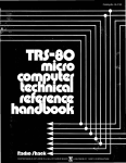
bus towards you. In the lower left corner is a brown connector plug with 3 jumper wires on it. (See Figure
7-1.)
Figure 7-1. Connector Jumpers
7·2
16KRA
Connect the negative probe of the ohmmeter to the center pin (GND). Be sure the voltage at the ohmmeter
probes is the same as the marked polarity. To check this, use a common diode of any type. The ohmmeter will
show a low resistance when the negative lead is connected to the end of the diode with the dark band near it.
Frequently, ohmmeters will have the polarity reversed so it is important to check.
With the negative probe connected to the center, ground pin, touch the positive probe to the right three pins,
one at a time. All of the readings should be greater than 100 ohms. Next measure between the + 8V and
-16V, the + 8V and the + 16V, and finally between the -16V and + 16V. The polarity of the probes is not
important for the last three measurements. If any of the readings were less than 100 ohms, the board should
not be plugged into the 5-100 bus until the cause is determined and corrected.
This preceding procedure will show any shorts before the voltage regulators, such as shorted capacitors,
shorted regulators, or shorts between traces (usually solder bridges). It is also necessary to check for shorts on
the regulated side of the voltage regulators. This can be done by measuring at the pins of any RAM chip.
Table 7-2 lists the required resistance readings. "Positive Probe" in the table means the probe supplying
positive voltage.
Table 7-2. Resistance Measurements at RAM Pins
Positive
Probe
pin
pin
pin
pin
pin
pin
pin
pin
16
16
16
1
8
9
9
8
Negative
Probe
pin
pin
pin
pin
pin
pin
pin
pin
9
8
1
16
16
16
8
9
Approximate
Resistance
8 ohms
13
500
8
100
30
150
75
If any of the preceding readings are much lower than indicated in Table 7-2, it can be assumed that a
problem exists on the board. At this point, a check should be made to see that all IC types correpond to the
16KRA Assembly Drawing (page 6-1) and that pin 1 of each IC is in the indicated position.
Also inspect the back of the board to see if any blobs of solder bridge two adjacent pins or traces. These can
be removed with a soldering iron. If any shorts cannot be visually located, it will be necessary to use a DVM
with a low ohms scale to find the short.
If the preliminary resistance checks are found acceptable, the hoard is ready to be plugged into a 5-100 bus
connector. Insert the board with the power off and connect a voltmeter between ground (pin 16) and + 5V
(pin 9) on any RAM chip. Turn on the power and immediately read the voltage. If it is not 4.75 to 5.25V turn
off the power immediately. Repeat the procedure with pin 8 (+ 12V) and pin 1 (-5V). If these voltages are not
within 1/2 volt of the nominal value, remove the board from the system until the cause is determined. If these
voltages check OK, leave the power on but check for overheating of the regulators. They should not be too hot
to touch. Check if any individual ICs are hot to the touch. If any are found, they can be presumed defective.
Now, look at the screen of the video display. Do the cursor and prompt look right? If so, proceed to the next
section. If any other characters have appeared, the board has "crashed the bus", or interfered with the
operation of the rest of the system.
7.4 THE 16KDT TEST
If the cursor and prompt have appeared properly, with no other characters displayed, address the switches as
4, 5, 6, and 7 as shown in Figure 7-2. Before attempting to load the test, make sure that there is at least lK
Hex of memory addressed as a block starting at zero. The test is not relocatable.
7·3
16KRA
Figure 7-2. Address Switch Positions
To load the cassette, first type CA <CR>, to activate the cassette motor, and rewind the cassette. Next type
the Mode Select key to return to command mode. The command XEQ <CR> will now load in the tape and
cause the tape to stop when done. The Data Path Test should appear on the screen. Press the space bar to
procede. Study the display carefully. The left column shows what was written, the center column shows what
was read back, and the right column marks any differences between the two. Are there any observable
patterns? Are there X's centered in a particular column? Does any column have all ones or zeros read from
it? Are the errors random? Are all ones or zeros read from memory? The display is organized with bit 7 on
the left and bit 0 on the right as a binary number would be written. Press the space bar twice again. Study the
display. Are any of the address lines indicated defective?
To use the Exerciser, enter a number between 4000-7FFF hex and the data to be written. The data is written
into memory as one byte of 8 bits, derived from the two hexadecimal data characters entered. Entering 00 Hex
for data writes a byte of all zeros; FF writes all ones. A typical entry might be 4000 FF <CR>. To stop the
Exerciser, press the Escape key. At this point a choice of any of the four tests or a return to SOLOS can be
made.
If no errors are found in #4, the Memory Test, press Escape to continue. If an error is found, the address of
the bad byte will be displayed. Since the test can only find one bad byte at a time, repeat the test until no
errors are displayed. To further pinpoint the error, dump nearby memory using the command DU <low
address> <high address>. Select the addresses for this command to include the error, but not to exceed the
capacity of the video display, 240 decimal bytes. If the error occurred at 4567 for example, dump address
4500 to 45EF. Usually a dump from XXOO to XXEF will include the error. When running the memory test,
the following data pattern is written into successive locations in memory: 00, 01, 02, 04, 08, 10, 20, 40, 80, 00,
etc. When examining a dump in the vicinity of an error, look for irregularities in this pattern. For example, if
the dump shows an area containing 00,01, 02, 04, 08, 10,22, 40, 80, the 22 is incorrect. To locate the bad bit
at this location convert both the correct and incorrect data words into binary patterns. The correct word 20 is
0010ססoo; the incorrect word 22 is 00100010. Thus the error is in bit one, the second from from the right.
If many errors are revealed by a dump, it is likely the problem is not bad storage locations in RAM chips.
Instead look for timing problems. See Section 7.5 below.
The memory on the card is organized as 4 pages. Each page contains 1000 Hex (4K decimal) bytes of data.
Each RAM chip is a 4K by one-bit storage so there is one RAM chip used to store one bit of data per byte.
Eight chips are thus used to store the eight bits in one data byte. Figure 2-1, page 11-3, relates the chip
location to the page and bit location.
7.5 OVERVIEW
Figure 7-3 presents the timing relationships during the typical operation of the 16KRA. All of the signals
shown are critical to the proper operation. A quick check of these signals, using the procedures given later,
will often reveal the source of the malfunction. To the left of Figure 7-3 is a column giving the names of the
signals shown, as they appear on the schematic and block diagrams. The second column gives an IC pin
7-4
16KRA
number where the signal may be ·found. Three signals: ~2 CLOCK, SYNC, and MEMWRT, come from the
processor, via the S-loo bus. A brief description of the remaining signals, which are all generated on the
16KRA board, is given below.
7.5.1 BOARD SELECT
This signal indicates that the processor has put the address on the address bus and that the page selection
circuitry has found a match between the high order 4 bits of address and one of the four page address
assignment switches. The first BOARD SELECT occurs when the processor is writing to the 16KRA. The
second one occurs when it is reading the data back to the 16KRA.
7.5.2
Me
A machine cycle (MC) usually occurs when the ~2 trailing edge occurs during SYNC. The MC labelled "write"
is initiated by MEMWRT. Notice that there is a MC before the "write" MC while the board is selected, called a
"spare read." Notice that no refresh (RC) follows it. The "spare read" occurs during the write operation,
initiated by a ~2 trailing edge during SYNC. It is not used during normal operations when installed in a Sol,
but during a DMA transfer it is used to enable the QU flip flop to request a WAIT state if a spontaneous
refresh is occurring.
7·5
16KRA
EXERCISER
UNSELECTED
12 CLOCK
U63- 5
SYNC
U63- 3
.
--1
.U
LJ
:
.....
•
CJ)
MC
U47- 6
SR
U55 - 7
RC
U47- 9
U55 - 9
MEMWRT
U44- 3
WE
U29-15
AR
U56 -10
CAE
U54-10
CAS
W54- 6
RAS
U48- 6
UNSELECTED:
READ
j
:
----!~-U
~
.
.~
!.
:[1'
:
:
U
n
••
nl-
••
•
~n
.•
••
.
I
.U""------;'"
i
~
U
U
~
OUTPUT ENABLE
.~
ILl
n
.
. .; . . -
---....;...
••
ul----------.;....------.+-------...::i-·
•
••
·•
I :•
rLJLn
••
.
n
n
....
:D
: UNSELECTED :
•
.LJ
i
.LJ
i
.
•
'-------...;........
:
CY
;
-:-----~---.---~-----~
!
U44- 8
WRITE
:
500
....:
nsec
:
BOARD SELECT
:
RUNNING
LJ
U68- I
:J>
Figure 7-3. 16KRA Master Timing
••
:•
~
7.5.3 SA
The synchronous refresh (SR) flip flop is clocked by the trailing edge of SYNC when the status indicates a
read operation by the processor. When SR is set, the end of CY will trigger an RC.
7.5.4 AC
In normal operation there are no spontaneous refresh cycles (RC). Refresh is accomplished after every MC
unless inhibited by SR during a write operation.
7.5.5 CY
A cycle (CY) will occur whenever there is an MC or an RC.
7.5.6
WE
WE is initiated by MEMWRT when the processor is addressing the 16KRA.
7.5.7 AA
The allow refresh (AR) circuit prevents a spontaneous refresh during a write operation.
7.5.8 CAE
The column address enable (CAE) occurs every MC unless an RC occurs at the same time.
7.5.9 CAS
The column address strobe (CAS) occurs during RAS. It is applied to all RAM chips to store the high order six
bits of the address. The chips that receive both CAS and RAS will have their outputs enabled.
7.5.10 RAS
A row address strobe (RAS) occurs for each MC or RC, and is used for page selection, and to store the low
order six bits of the address.
7.5.11 OUTPUT ENABLE
OUTPUT ENABLE occurs when the processor reads from the 16KRA and PDBIN is occurring.
7.6 BUS CAAStES
If your board interferes with the operation of the processor through the SI00 bus, use the following procedure. Bus crashing is normally due to either a completely incorrect signal or a signal being put on the S-I00
bus at the incorrect time. The surest way to locate these problems is to open up each line, one at a time, until
the problems clear. However, many times the problems can be traced by looking at the S-IOO bus for a signal
that is stuck high or low or has an intermediate value at times. The following S-IOO bus signals are used by
the 16KRA.
00 Bus: 35, 36, 38, 39, 40, 88, 89,90 or U50, (3,6, 11, 14), U51 (3,6, 11, 14)
Address Lines In: 29,30, 31, 32,33, 34, 37, 79, 80, 81, 82, 83, 84,85, 86, 87
010 Bus: 95, 94, 41, 42, 91, 92, 93, 43 or U68, (3, 5, 7, 9)1 U69, (3,5, 7, 9)
With the scope time base set at I usec per division look at each one of the above signals. All signals should be
a series of pulses which switch between ground and 4 to 5 volts clearly with no ramps or intermediate values.
If these signals appear correct, check the lines listed in Table 7-3 below.
7-7
16KRA
Table 7-3. Bus Line - IC Pin Signal Checks
BI.- Pin
Name
IC #
Response
45
SOUT
U60-9
Low at all times or Signal
46
SINP
U60-8
Signal
97
SWO
U72-13
Signal
47
SMEMR
U55-2
Signal
78
PDBIN
U62-12
Signal
67
Phantom
U62-13
5-6Volts
68
MEMWRT
U44-3
Signal
24
f/J2
U63-5
ClockSignal
77
PWR
U46-14
Signal
76
SYNC
U63-2
Signal
69
PS
U68-13
High
72
PRDY
U68-11
Signal
3
XRDY
"
70
PROT
U70-9
Low
20
UNPROT
U70-4
Floating 2V in Sol
99
POC
Jumper Area B
High
If this still doesn't help locate the trouble, try insulating the S-loo bus contacts to locate the pin with the
interfering signal. This can be conveniently done by folding a piece of paper over one half of the edge
contacts before inserting the board. Use progressively narrow pieces of paper until the interfering pin is
pinpointed. Correct the. problem or keep this pin insulated. Clear the bus so that the test program can be
loaded and run for further diagnosis.
Many times the problem arises because data is enabled onto the bus at the incorrect time. To disable the
outputs, remove the jumper from area C and ground the pin above the "c" of area C. Then proceed with
testing.
7.7 THE RAM CHIP
7.7.1 Overview
The RAM chip is organized as 4K by I-bit storage. Internally, the memory is organized in a matrix of 64 rows
by 64 columns. With the 2104, the lower 12 address bits from the processor are divided into two 6-bit
sections. The lower six bits (AO-A5) form the row address and the higher six bits (A6-11) form the column
address. These two 6-bit addresses are presented to the RAM sequentially. When the Row Address Strobe
(RAS) arrives at pin 4 of the RAM, the lower 6 bits are stored in an internal register. Also an internal timing
sequence is started. After a 100 nsec delay, the RAM has enabled itself to receive th~ column address. 150
nsec after RAS the Column Address Strobe (CAS) is applied to the RAM. This stores the higher six bits and
begins another internal timing cycle. The leading edge of CAS will cause the output to enter the high
impedence condition. A fixed time later the data will appear at the output pin. This data is internally latched
and will remain stable until the next CAS arrives. If CAS is applied to a RAM with no RAS, the output will be
at the high impedence state until the next cycle.
Chip selection is accomplished as follows: The chip select pins are always enabled. CAS is applied to all four
pages. The selected page will also receive RAS. The output pins of all 4 RAMS that store a given bit of data
are tied together. The three unselected pages will have their outputs enter the high impedence state while the
7-8
16KRA
chips that received both HAS and CAS will enable their data output. The cycle is the same for both read and
write-the only difference being the state of Write Enable (WE). When WE is low, data will be written into a
chip, when high, data is read. A bad RAM can cause a bit on all four pages to appear bad.
7.7.2 Trmmleshootlng the RAM
It is possible to examine the compiete operation of a RAM by using the Exerciser program with the scope.
Trigger the scope on pin 3 (WE) of any RAM. While WE is low, the address inputs will correspond to the
selected address. During HAS the addresses may be correct or they may originate from the refresh cycle. To
examine the operation of a bit of data in a given RAM chip, two things are necessary. First the address must
be entered into the exerciser, then a space, then the data to be written into the selected byte must be entered.
A byte is represented by two hex numbers for the Exerciser program. If all zeros are desired, enter 00. If all
ones, enter FF, etc. All of the signals on the RAM chip itself are inverted with respect to the corresponding
inputs to the 16KRA from the bus. This occurs because the driver chips that buffer all pins on the RAM
invert the signals. With the Exerciser running, set the scope to 5 usec per division. Look at pin 3 on the RAM.
The scope should show 2 negative pulses; the pulse being triggered on and another 45 usec later. Put the
scope in the intensified mode with a delayed sweep rate of .2 usec per division. Center the light section on the
central WE pulse and hit the delay mode button. Now look at every other signal on the RAM, as follows: First
check the voltages on any RAM that isn't working properly. Then check to see that HAS appears only at the
selected RAM page. Check to see CAS is there, then check the address lines.
To understand signals appearing on the RAM address pins, write out the address given to the Exerciser in
binary. Divide the low order 12 bits into two groups of six. The invert each bit to see how it actually looks at
the RAM. For example: 4444 Hex in the Exerciser program translated into binary, will be
0100
0100
0100
0100
The first 4 digits select a page and provides HAS to the chosen page. The lower 12 bits can be divided into 2
groups of six, then inverted two groups of six:
010001
t
A12
inverted:
•
10110
000100
\
lAO
Ill0ll
This will correspond to the addresses seen by the RAM during each half of the address input cycle. The lower
six bits, AO through A5 will appear first, then the higher six bits, A6 through All. Figure 7-4 shows which
RAM pins correspond to which address lines.
If everything looks correct at this point, look at the data-out line as follows: First, set the scope probe on
OUTPUT ENABLE U68-1. Still triggering on WE, set the delayed sweep to .2 usec per division, and switch to
intensified mode. When this signal goes low, the data from the RAM is placed on the data bus. For the
Exerciser program, this is about 3 usec after WE. Move the delayed sweep vernier so the intensified portion is
centered over the signal on U68-1, and switch to delayed mode. At this time, examine pin 14, Data Out, on
the RAM. It should correspond to the data input during WE. This signal, as all others on the board, should be
clearly high or low while U68-1 is low. However, the outputs will float at 2 volts for a short time after CAS. If
any signals at the RAM output appear stuck high or low or occasionally have an intermediate value except
after CAS, this is incorrect. However, because all the RAM outputs are tied together, it may be necessary to
isolate the outputs to locate the problem. The Data Path Test can help locate bad RAMs. The Data Path Test is
run at address 4000 only, but by using the paging switches, you can address any page to 4000. If the Data
Path Test fails on three pages and runs well on the last, unlikely as it may seem, this good page probably has
the bad RAM.
7-9
16KRA
+12V
A3,A9,RC5
A4,AI0,RC6
2104-6
RAM
A5,AII,RC7
RAS
WE
DIN
-5V
Figure 7-4. RAM Chip Pin Assignments
There are several test addresses used with the Exerciser to find addressing problems.
IT the memory passes the Data Path Test but the Addressing Test shows several bad lines, there are two
addresses: 4FCO and 403F, which will test for problems in the multiplexers.
The signals shown in Figure 7-5 should be found at the RAM on all the address inputs at the selected page
during WE while the Exerciser is running. The top two waveforms are for address 4FCO and the bottom two
are for 403F. Any data word can be entered for this test.
When using these two addresses, any address line shorted to Vee or ground will be evident. Measure the pulse
width on the address multiplexer outputs at pins 7 and 9 of U65, U66 and U67 while the Exerciser is running
at address 403F. If any pulse width is greater than 145 usee, the corresponding multiplexer may have a gate
that is too slow. Sometimes, two RAM lines are shorted together. Two test numbers will help find these. 4AAA
and 4555 will cause the addresses to alternate on adjacent pins. If a short is present, the address lines shorted
will usually have an intermediate value when the two lines have opposite values. IT the addressing test says bit
12 or 13 is bad, look to U42 for a page selection problem or to the drivers to the RAMS.
I I
4FCO
RAS
i""~~-A-N-Y
ADDRESS LINE =250 nsec
_I
=375nsec
I 25-ns-e-c-----+-
403F
125
=375 nsec
nsec={F
R~S
ANY RAM ADDRESS LINE =125
nSlC
Figure 7-5. RAM Address Signal Waveforms
7·10
16KRA
7.8 THE WRITE REQlEST FLIP FLOP
Refer to Figure 7-6. The operation of the Write Request (WR) flip flop starts with a write operation to the
16KRA board. If the board is unprotected (U70-3 high), selected (63-11 low), and a write operation is in
progress, input to K, U63-8, will go low. Input to clock will go high for .5 usec, 1.5 usec later. This will clock
the WR flip flop and cause the WR signal on pin 10 to go low. This will initiate a chain of events which will
lead to WE being clocked, MC being set, the delay line being triggered, and eventually U57-8 and U45-11
going low for 200 nsec which resets WR through pin 11. This reset normally happens about 150 nsec later
under normal circumstances (no CY in progress) .
•
8Q\RD PROTECT
U70-3
SELECT
U63-11
MEMWRT
U44-4
SELECT OR SYNC
U61 -3
HIGH
•••
•
••
••
•
WRITE
IOOn..c--i
1
•
I
U63-8
INPUT TO CLOCK
U45-12
OUTPUT WR
U45-1O
RESET PUlSE
U45-11
U57-8
·••••
•
·•
L
••
INPUT TO K
l-
Figure 7-6. Write Request (WR) Timing
7.9 WRITE ENABLE OPERATION - WE
Refer to Figure 7-7.
When WR (U45-IO) is clocked low, 2 things are possible, depending on the status of CY. CY may be high for
a maximum of 520 nsec. After this time it will go low and cause U60-4 to go high. CY may be low, in which
case U60-4 will go high immediately. In both cases, the WE flip flop will be clocked, and WE (U46-7) will go
low. This will set the MC flip flop and start a machine cycle. Also WE (U46-6) will go high and along with
MEl and ME2, and enable the memory drivers. When the machine cycle is started, the delay line is driven.
After 350 nsec U57-6 generates a reset pulse which resets MC and WE.
7.10 MACHINE CYCLE - Me
Refer to Figure 7-7.
A machine cycle (MC) occurs under two different sets of circumstances. It is about 350 nsec long and is always
reset through U57-6 going low from the delay line. During a write operation, it is set by the WE flip flop.
However, most of the MCs are caused by read operations, and originate from a clocked mode. MC is clocked
whenever the c1J2 clock goes low while SYNC is present or the Queue (QU) flip flop is set. If a refresh cycle is
in progress when c1J2 goes low, MC will not be clocked immediately. Instead the QU flip flop will be set and
then MC will be clocked as soon as the next c1J2 comes along. After the MC is over, refresh cycle is initiated by
the end of CY. This inserts refresh cycles often enough to prevent spontaneous refresh cycles from occurring.
7-11
16KRA
7.11 CYCLE FLIP FLOP - CY
Refer to Figure 7·7.
The Cycle (CY) flip flop is set to its active mode (U55·9) high whenever an MC or RC is initiated, through its
R input (pin 15). It is clocked to its inactive mode when U57-6 from the delay line goes high. In effect it
starts when there is an MC or RC and ends 100 nsec after MC or RC is reset. This flip flop is used to insure
that the cycle which caused it is finished before any new cycle can be initiated.
WE
U46-6
MC
U47-6
DELAY INPUT
U61-8
100 nsec
100 ns TAP
U57-5
150 ns TAP
U57-2
250 ns TAP
U57-4
350 ns TAP
U57 -I
RESET PULSE
U57 - 6
ME
U44-6
CY FLIP FLOP
WR RESET
"!
!
~
I
r
I
I
II
I
U
I!
II
U55-9
U57- 8
U45-11
Figure 7-7 Cycle (CY) Timing
7.12 SYNCHRONOUS REFRESH - SR
See Figure 7-3.
The synchronous refresh (SR) flip flop controls the normal initiation of the refresh cycle. SMEMR is a status
signal put out by the processor. It is put on the data bus during SYNC. It is latched by ~2 going low during
SYNC and remains stable on the S-loo bus until the next SYNC pulse. SMEMR, when high, indicates an
instruction fetch, memory read, or stack read. It will be low during any write operation. When SMEMR is
high, the end of SYNC will clock the SR flip flop 80 that SR goes low. ~2 going low during SYNC will also
initiate an MC and therefore a CY. When CY ends, and SR is low, RC will be clocked to start a refresh cycle.
As soon as the RC is started, it will reset the SR flip flop so that only one RC occurs for a given SYNC pulse.
7.13 THE ALLOW REFRESH FLIP FLOP - AR
See Figure 7-3.
The allow refresh (AR) flip flop has one purpose. This is to prevent a spontaneous refresh at critical times
during a write cycle. SWO is a status signal put out by the proccessor. It will go low whenever the processor
7-12
16KRA
begins a write operation. It will be put on the data bus during a SYNC signal. Then it is latched when ~2 goes
low and will remain stable on the bus until the next ~2 low during SYNC. If SWO is low, the board is
selected, and unprotected, the AR flip flop will be clocked low at the end of SYNC. This will prevent a
spontaneous refresh until AR is set high by the ,same signal that resets WR. If SWO goes low but the board is
not selected, SWO will not reach the AR flip flop.
7.14 PAGE SELECTION
7.14.1 Overview
Each page consists of 4K bytes. Each 4K page can be set to one of 16 different starting addresses. This choice
is done through the paging switches and the LSl36 exclusive-OR open collector ICs, Ul9, 20, 40 and 41. Each
set of four switches can be set from 0 to F Hex. This corresponds to a starting address of ססoo through 61,440
decimal. Each LS136 contains 4 exclusive-OR gates. The outputs of these 4 gates are connected together.
Because the outputs are open collector, there will be no conflict if some of them are high and some low at the
same time. However, in order for an output line to go high, all four gates that are tied together must go high
at the same time. Then the pull-up resistor will pull the line up to a high condition. In order for all four
outputs to go high simultaneously, a match is necessary at the inputs to each of the four gates. When a switch
is pushed up, (ON), it grounds one end of the exclusive-OR input. When the address line connected to the
other input goes high, that particular gate will remove its low from the output line. Only when all four gates
are matched can a particular starting address be selected.
A memory system must not have more than one page set to start at the same address. If this is accidentally
done, both pages will fight for control of the bus. In order to prevent this problem, the 16KRA contains an
inhibit circuit. This circuit consists of 6 open collector inverters. The inverters are wired to establish an order
of priority. If two or more pages on this board are set to the same starting address, only one will respond. The
switch in the top left corner will inhibit the other three. The top right will inhibit the lower 2 switches, and
the lower left will inhibit the lower right.
7.14.2 Trcxmleshooting the Page select Circuit
To test to see if a paging IC is operating correctly at all possible addresses, Jumper U44-8 to ground. Load the
16KDT diagnostic test. Proceed to the Exerciser and enter FOOO 00 <CR>. Push all the switches to the up
(ON) position. Put channel 2 of the scope on U45-12, (delayed MEMWRT) with the Exerciser running. Set the
scope at 5 usec per division. Figure 7-8 shows the required pulse pattern.
-II- ::::::2}1sec
J~~30}I_sec ~~psecOO,----_~~L
Figure 7-8. MEMWRT Pulse Pattern
Notice the one thin pulse near the group of 2 wider pulses. Set the scope to the intensified mode and the
delayed sweep to 1 usec per division. Center the intensified area around the thin pulse and change to delayed
trigger. You should have one pulse visible about 500 nsec wide. Now look at U19-8 with the other probe. Two
pulses about 2 usec wide, separated by 1.5 usec, should be observed. These pulses represent selection of a
particular page on the 16KRA by the diagnostic test. The first pulse occurs when the test is writing to the
16KRA. The second one occurs when the test is reading back from the same location. This shows that the
highest priority page has been selected.
Next look at pin 8 of U20, U40, and U41. They should all be low. Push switch 1 (top row) down to remove
the inhibition by the first page and look at U20-8. It should now look like Ul9-8 did. Push switch 5 (top)
down and look for the same waveform at U40-8. Now push 1 (bottom row) down and look for the same
waveform at U41-8. This test checked the page inhibit IC U59.
To check individual pages now, go back to all switches high. Now push 1 (top row) down and see that U19-8
goes low, then push it up and push 2 down and see that U19-8 goes low. Repeat with switches 3 and 4. Now
leave 1 down and proceed to 5, 6, 7, 8. Start with all up and check U20-8 to see the board select signal.
7-13
16KRA
Repeat the same procedure, switching one down at a time while checking U20-8. Then leave 5 down and go to
the lower switch. Look at U40-8 for switches 1-4 and U41-8 for switches 5-8.
This procedure has checked for most of the paging problems but to be certain, the whole procedure has to be
repeated with the address switches low. Press the escape key and 3 to get the Exerciser. Now type 0900 00
<CR>. The memory test is stored at ססoo addresses to 0800 so don't be tempted to enter address ססoo to the
Exerciser. Push all the switches low and check UI9-8. In this case it will be a long pulse followed by 2 short
ones. Push switch 1 up and check U19-8 for a low level. Push 1 down and 2 up and check again. Repeat for 3
and 4. Then leave 4 up and repeat with 5-8, one switch up at a time while looking at U20-8. Leave 8 up and
check page 3 by switching up the lower switches I to 4 one at a time while looking at U40-8. Leave 4 up and
repeat with 5-8 while checking U41-8. This procedure will catch all possible page address assignments problems but if an intermittent problem occurs, suspect the switches themselves.
Check to be sure that the two SIP resistor networks are not installed backwards. First set all 16 address
switches off. Check the resistance between the two pins on each network farthest from the edge of the board.
The resistance should be 2.2K. 4.4K indicates a backwards installation. Both networks must be mounted
correctly, or the paging will not work properly.
If a problem is found while testing the page select circuitry, check the address lines and switch lines at the
suspected IC,using Table 7-4.
Before proceding to the next test, remove the jumper from U44-8.
Table 7-4. LSl36 Pin Assignments
Address Line#
Input Pin
toLSI36
Switch
Number
Matched with
LS136Pin
A12
1
lor 5
2
A13
4
2 or 6
5
A14
13
3 or 7
12
A15
10
4 or 8
9
7.15 READY LINE
7.15.1 Queue Operation· QU
The Queue (QU) flip flop, U45, controls the Ready line to the processor, PRDY, or XRDY, as selected in
Jumper area E. If QU goes high while the board is selected, the processor will receive a request to enter the
wait state. The operation of the QU flip flop is complicated because it is normally clocked both high and low
and, also is set and reset through its asynchronous inputs. In normal operation, the QU flip flop is never used.
A wait state is only required when a spontaneous refresh interferes with the normal board operation. No
spontaneous refreshes are generated in normal operation; refreshes are generated through the operation of the
synchronous refresh (SR) flip flop. During a write operation it is important that nothing interferes with the
write operation after the WR flip flop has been clocked The WR flip flop is clocked after the time for
requesting a wait state has passed. To insure that a spontaneous refresh never occurs during this critical
period, the AR flip flop inhibits spontaneous refresh until the write cycle is started. When the write cycle has
started, CY inhibits refresh. Only after the write cycle is completed can a refresh finally occur. A write cycle is
normally preceded by a spare read cycle. When the trailing edge of 4J2 occurs during SYNC, MC is clocked. At
this point there are several possibilities. If a spontaneous refresh is in progress, MC will not be clocked high.
, Instead QU will be clocked high. If MC is clocked high but a spontaneous refresh has also started at that exact
moment, before inhibition is complete, QU will be set high indicating a coincidence cycle. QU is held reset
unless the board is selected or SYNC is present. If QU is high, it will be reset as soon as SYNC is over unless
the board is selected. Although QU may be set any time that 4J2 and SYNC are present, the READY line will
not be pulled low unless the board is selected.
In a read or "spare read during write" cycle, MC is clocked by 4J2 trailing edge with SYNC present. However,
if a refresh cycle is in progress when MC is clocked, CY will be high and this will force the MC J input low.
MC will remain low. Because MC remains low and SYNC is present, the J input on the QU flip flop will be
7·14
16KRA
high. When ep2 delayed occurs approximately 30 nsec later, QU will be clocked high. The processor will enter
a wait state after T2 of the processor cycle is complete. All of the bus lines will remain stable except for ep2.
With QU set, U61-6 is high, even though SYNC is no longer present. When the refresh cycle is over, the J
input on MC will be high. When ep2 occurs, MC will be clocked high. With MC high, the J input of QU will be
low. Thirty nsec later when ep2 delayed occurs, QU will be clocked low. The processor will start at the
beginning of the T3-processor cycle. The processor will then complete the write or read cycle as if no wait had
occurred.
7.15.2 Troubleshooting The Re.dy Line
In order for the 16KRA to request a wait state through the Ready line, the QU flip flop must be set and the
board selected. These signals are combined in U68. Problems with Board Select will usually crash the bus or
prevent the 16KDT test from working. If the processor stops accepting inputs from the keyboard, it is most
likely caught in a wait state. To clear the processor, remove the Area A jumper and ground the W pin. If the
processor is still caught, refer to Section 7.6, Bus Crashes. With the CPU working, load the 16KDT tape and
troubleshoot the 16KRA. Normally no wait states are generated, so deactivating the Ready line driver has no
effect on the diagnostic test. The 16KRA can cause a permanent wait state if something is preventing the MC
flip flop from being clocked. In this case the QU flip flop will be clocked high but never clocked low again.
Because the wait state option is not normally used, the 16KRA may appear to be operating properly until a
DMA is attempted. If the 16KRA passes both memory tests, but will not work with a DMA device, the
operation of QU must be checked. The QU flip flop will go high when it is either clocked or set. It is
necessary to test both clocked and set modes of operation to be certain it is operating correctly. The following
procedure will test both modes of operation. Replace the jumper in Area A.
First load the 16KDT and advance to the Exerciser. Enter an address that will select the board and start the
Exerciser. Set channel 2 of the scope on pin 3, WE, of any RAM chip. Set the sweep to 5 usec division and
• adjust for a stable display. Now connect a 20K pot across R12. Put the scope probe for channel 1 on U48-8
and adjust the pot until several pulses are evident. Set the delayed sweep to .2 usec per division and intensified mode. Center the bright area on one of the U-48 pulses and switch to delayed sweep. Note where this
pulse now appears on the screen and put the channel 1 probe on the jumper to Area A. In the same place on
the scope screen there should be a pulse of the same duration. This checks the operation of the set and reset
inputs of QU. Now switch the scope back to the intensified mode and put the probe on the Area A jumper
again. It should be possible to adjust the pot so that many more QU pulses appear than U48-8 pulses. This
tests the clocked inputs. The QU pulses are normal because the board is not selected. If you pass both these
tests and the DMA still does not work, try the Page Selection test, Section 7.14. Remove the pot before
proceding. In many cases the address switches are set differently for the DMA device than they are for the
memory tests. If the address selection is not working properly on the DMA addresses, the DMA won't work.
Also check the AR flip flop and the spontaneous refresh generation. With the Ready line held low, there
should be a refresh cycle every 4-6 usec. If all these tests are good, suspect a slow RAM chip, or a problem
with U70.
7.16 THE WAIT STATE OPTION
If the jumper in Area A is put to 1 instead of 0, the following sequence of events occurs. The QU flip flop is
not set so QU is high and the J input on U56 is high. U56 is held reset when SYNC is present, keeping its Q
output high, causing a request for a wait state through U68 on the PRDY or XRDY lines. On the ep2 trailing
edge, MC will be clocked, starting a machine cycle. The processor will recognize the request and enter a wait
state after T2 is over. By this time SYNC will have gone low, removing the reset. The next ep2 trailing edge,
500 nsee later, will now clock U56, ending the wait request on PRDY or XRDY. While the processor is in the
wait state, it samples the Ready line which is now high, and begins T3 exactly one clock period later than it
would have without a wait request. Later, when SYNC goes high again, U56 will be reset and a new cycle may
start. The processor only samples the Ready line at a point near the trailing edge of ep2 during T2 so the fact
that the Ready line is low for the greater part of the cycle doesn't affect the processor operation. If the QU flip
flop is set because MC wasn't clocked, U56 will be held reset until MC is clocked. When MC is clocked, QU
will be clocked low 30 nsec later. SYNC will still be high so U56 will continue to be reset until SYNC ends,
extending the period that the Ready line is held low. When the processor samples the line again and finds it
low, it prolongs the wait state.
7·15
16KRA
7.17 REFRESH CYCLE FLIP FLOP - RC
Refer to Figure 7-3.
The time the Refresh Cycle (RC) £lip flop is high defines a refresh cycle. It is the same length as an MC and is
reset by the same signal. It is initiated through two different mechanisms. Every time RC is high, Ql is turned
on and its collector goes to ground and discharges C46, provided the Area D jumper is installed between D and
DN. After the RC is over, Ql is turned off and C46 starts to charge. Mter about 4-6 usee, C46 will have
charged enough to trigger U62, a Schmidt trigger gate. This can initiate another RC which will tum on Q2 and
discharge C46. This process will repeat unless inhibited. Normally this spontaneous cycle does not occur
because RC is clocked more often than 6 usee. This cycle takes over if the processor stops for more than 6
usee, as in a wait state. This spontaneous refresh cycle is not synchronized with the processor clock, and
several mechanisms are needed to inhibit it at unwanted times. If a CY is in progress, the Schmidt trigger,
U62, will be disabled until the CY is over. Also the refresh is inhibited by the AR £lip flop in preparation for
a write cycle. Under normal circumstances, RC is clocked when CY ends if the SR flip flop is set. This inserts
a refresh after almost every MC.
7.18 THE REFRESH CIRCUIT
7.18.1 Overview
Refer to Figure 7-9, Refresh Page Selection Timing. The refresh addressing circuit is controlled by two 4-bit
counters, U49 and U64, connected as an 8-bit counter. The counters have two inputs. Pin 10 is an enable
input, connected to CAE. The column address enable £lip flop (CAE) has its J input connected to the MC £lip
flop. When there is no MC cycle the J input is low and CAE will not be clocked high. If an RC is triggered,
CAE will be high, the counters will be enabled, and ME will advance the counters on rising, (trailing) edge.
The counter will remain stable until the next RC is over, when it will be advanced again. The enable input of
the high order counter U64, is connected to the carry out input of U49. The carry out is only enabled when
CAE has enabled the low order counter, U49. Pins 13 & 14 of U49 are the two least significant bits and are
used to form the paging. This has the effect of sequentially refreshing pages 1-4 at a given address, then
advancing the address counter by 1. The six address lines from the counter are switched by the multiplexers
to the address lines of the RAMS when an RC is present and CAE is low. RC is connected to pin I of U42.
When RC is high and a refresh is in progress, U58 will act as a 2-bit to 4-line binary decoder. The multiplexer
U42 selects the 4 outputs of U58 to drive the 4-page lines.
The six high order outputs of the counter are stable for 4 entire refresh cycles. The three address multiplexers
will output the counter address during an entire RC because there is no CAE during an RC. This counter
address is gated by U48-3 (page 1 or 2) or U48-11 (page 3 or 4) at the address drivers of the RAM chips. The
RAS Pulse is gated by the 4 page lines at the RAS drivers (U30). The page of memory which receives RAS
refreshes its row specified by the refresh address.
7.18.2 Troubleshooting Refresh
Refer to Figure 7-10, RAM Address Line During Refresh, and Figure 7-11, RAM Refresh Timing, Page 3 and
4. To simplify troubleshooting the refresh circuit, ground pin U68-11. This will put the processor in a wait
state and prevent any MCs from occurring. Look at U49-2. You should see a waveform that repeats a negative
pulse 400 nsec long at about 4 usee intervals. If you don't see this, the problem is in the generation of the
spontaneous RC cycle. If this is present, check to see that U49-10 is high. This enables the counters. Then
look at all the output pins from the counters. Each output should have a square wave signal with the periods
listed in Table 7-5 (based on a 4-usec interval).
U49-14
U49-13
U49-12
U49-11
8
16
32
64
usee
usee
usee
usee
U64-14
U64-13
U64-12
U64-11
128 usee
256 usee
512 usee
1024 usee
Table 7-5. Counter Periods.
If these are acceptable, test U58. Set the scope to 5 usee per division, and trigger on U49-11 and examine U58,
4, 7, 9, 12. Each signal should appear as shown in Figure 7-9. You should find a positive pulse about 4 usee
wide, occurring every 16 usee. Then check U42. With the scope still triggered by U49-11, examine U42, 4, 7,
9, 12. There should be a positive pulse about 400 nsec wide, occurring every 16 usee. If all of these tests are
7-16
16KRA
checked OK, the problem is probably not in the refresh addresses. All of the signals at this point are
multiplexed into the rest of the address circuitry. If the rest of the memory card is working, the refresh is
most likely working also. As a final check, trigger is on U64-11 with the sweep set at .1 msec per division.
Refer to Figures 7-10 and 7-11. Figure 7-11 represents a more detailed view of some signals in Figure 7-10.
Looking at any RAM chip pins 10, 11, 12, you should see groups of 2, 4, and 8 respectively, negative pulses.
Looking at RAM pins 7, 6, 5, you should see groups of 16, 32, and 64 negative going pulses. This checks the
operation of the address multiplexers U65, U66, U67.
7·17
16KRA
COUNTER ENABLE
U49-IO
I··
q
RC
U42-1
ME
U49-2
U58-2,6
---Ii
'j
I
U58,II,I3
U44-12 - - - - .
I
~
-II
U58 -4
!
U58 -7
----=
f
U58-9
I
U
U
U
I
1
1
I
----=
U49-13
CD
U
'I
U49-14
SELECT H=B
....
n n n n n__
H;,"o1
I
I
I1
I
I
IL
I
U58-12:
U42-4
PAGE
U42-7
n
.
PAGE 4
n
n
U42-9 - - - - - - - - ~
~
PAGE 3
U42-12
U~-
1
1 _
Ir----11.--___,
I
Ir--I
,
I
1__
1
nL
:IJ
•
Figure 7-9. Refresh Page Selection Timing.
_
I
I
n
""""'-_1__
,
_
I
I
PAGE 2
U
n
n~
_
,_,_
_
_
U49-12
PIN 10 RAM
U49 - "
PIN II RAM
U64 -14
....•
....
co
PIN 12 RAM
U64 -13
I
I
I
I
PIN 7 RAM
U64 - 12
PIN 6
..
I
I
RAM
U64-11
r
I
".".
.
I
".".
r
I
.
.
I
PIN 5 RAM
I
I
Figure 7-10. RAM Address Line Timing During Refresh
IL-
I
..
L
".
I
_
PAGE I
nsec
4
~
:zI
:.
3
2
I
4
2
3
I
4
2
3
I
4
2
3
I
4
2
3
I
4
2
3
I
4
2
3
I
4
2
3
I
4
2
U49-12
--.-J
ADR. MUX
U67-9, U31 - 6
3
3
4
I
4
I
3
4
I
f
3
4
3
4
I
3
4
I
3
4
I
3
4
3
I
.......
L
3
4
3
U31-5
RAM
U31-7
PAGE 4
RAS
U30 -10 --,
PAGE 3
RAS
U30 -15
COUNTER
U49-11
ADR. MUX
U67-7
RAM
U31 -15
COUNTER
U64-14
ADR. MUX
U66- 9
PIN 12
I:
:
:
PIN 10
PINII
..
4
COUNTER
4
~
I
_..-...-.+-..................-+-.......--""_......-"'I--a..-_..-._ _.-...-.._--I.--""....................I....-a..-..-...-._.............-.._.......--I.--""_......
RC
PAGE 30r4
0
3
r-4-6nsec
U31- 4
4- 6
-...•
2
--j
RAM
~
r--l
I
I
r--l
I
I
I
I
I
I
~
I
I
I
I
r--l
r--l
I
I
I
I
I
I
I
U31-2
Figure 7-11. RAM Refresh Timing - Page 3 and 4.
I
r
r--r
11II
I
I
1.....
_
APPENDICES
1
Ie Pin Configurations
2
Memory Test Programs
16KRA
I
I
I
I
I
I
I
I
I
I
I
I
I
I
I
I
I
I
I
I
I
I
I
I
I
I
I
I
I
I
I
I
I
I
I
I
I
I
I
I
I
I
I
I
I
I
I
I
I
I
I
I
I
I
I
I
I
I
I
I
I
I
I
I
I
I
I
I
I
I
I
APPENDIX
1
Ie PIN CONFIGURATIONS
APPEtOX 1
A1·1
18KRA
74109
74132
74136
74153
1A
1B
2B
2A
1Y
2Y
GND
74163
74157
INPUTs
INrufS
,..-J<--.. OUTPUT ,..-Jo--..
VCC STROBE
4A
48
4Y
3A
3B
OUTPUT
3Y
OuTPUTS
3Y
.
OA.TAIWUT$
IV
~
2Y
GND
SELECT ~
INPUTS OUTPUT INPUTS OUTPUT
APPEraX 1
A1-2
1EJCRA
75365
74175
Vee.
4Q
,,0
CLIAR
1Q
'0
'0
30
JO
JO
CLOCk
20
2G
lO
GND
7805' or 7812
P,n 1 InL''''
i
BaMI
P,n '2 r ,.• lllyl If '"'tterl
P ..... 3 (;'o""d
to pIn
ICOIl~('O'l
3
2104
Vss
CAS
"oUT
a
.......
I
WE
WRITE e-NA'ilE
CAS
COLUMN ADDRESS STROBE
eli
CHIP SELECT
DATA IN
DATA OUT
v••
vee
POWER l-SVI
POWER (+5V)
1100
POWER f+12V)
Vss
GROUND
0,.
o"UT
I lIAS
APPEtOX 1
A1-3
PIN NAMES
ADDRESS INPUTS
ROW ADDRESS STROBE
16KRA
I
I
I
I
I
I
I
I
I
I
I
I
I
I
I
I
I
I
I
I
I
I
I
I
I
I
I
I
I
I
I
I
I
I
I
I
I
I
I
I
I
I
I
I
I
I
I
I
I
I
I
I
I
I
I
I
APPENDIX
2
MEMORY TEST PROGRAMS
16KRA Short Memory Test Program
The test program on the following page is designed to check the 16KRA Dynamic ReadlWrite Memory Module
for proper operation. It is a short test which may be easily loaded. For a more thorough test, use the long
memory test which follows.
NOTE
This test program is written for use with Processor Technology
SOLOS or CUTER monitor programs. If you are not using either,
you will need to modify the program to work with your monitor.
To use the program, proceed as follows:
1) Set the Page Select Switches (SWI and SW2) for continuous memory from 0 to 16K. The switches in Figure
4-1 are set in this configuration.
2) Load the program on the following page into memory at C900 (Hex). The Sol computer contains built-in
system memory at the necessary locations. The program could be reassembled to run at a different address if
necessary.
3) To run the program EXECute C900. The program runs continuously unless an error is encountered; then it
returns control to SOLOS/CUTER. If it runs for 10 minutes without the SOLOS/CUTER prompt appearing,
you may consider the 16KRA as having passed the test. You may then return control to SOLOS/CUTER by
pressing the UPPER CASE and REPEAT keys together.
4) Once the test is loaded into memory and runs correctly, you may want to save it on cassette tape for later
use, using the SOLOS/CUTER SAVE command.
When the program reads data which does not match the data written, it stores the address where the error
occurred, the data written, and the error data read, in four locations of memory. To display this information,
enter the command DU C949 C94C <CR> and refer to the source listing for interpretation.
The longer test is more useful for diagnosis since it displays a complete map of errors rather than just the first
had location encountered.
APPEtOX2
A2-1
16KRA
*
C900
C900 2E 04
C902 22 47 C9
C905
C906
C907
C908
AF
37
F5
F5
C909 21 00 00
C90C Fl
C90D 77
C90E 17
C90F F5
C910
C911
C912
C914
23
7C
FE 40
C2 OC C9
C917
C918
C919
C91A
Fl
Fl
F5
F5
C91B 21 00 00
C91E
C91F
C920
C921
Fl
F5
BE
C2 36 C9
C924 Fl
C925 17
C926 F5
C927
C928
C929
C92B
23
7C
FE 40
C2 IE C9
C92E
C92F
C930
C931
C932
C933
Fl
C936
C937
C938
C939
C93C
C93D
C93E
*
**
*
ORG
XEQ
16KRA SHORT MEMORY TEST
*
*
*
WRITE
LOOP
*
*
*
*
*READI
*
*
*
Fl
17
F5
F5
C3 09 C9
56
SF
EB
22 4B C9
EB
54
65
APPENDIX 2
*
OC900H
OC004H
ERROR
**
MVI
SHLD
L,4
RTRN
XRA
STC
PUSH
PUSH
A
PSW
PSW
CREATE MASTER PATTERN
SAVE IT ON STACK
AND A COpy TO WORK WITH
LXI
H,O
FILL MEMORY FROM 0 TO 3FFF
POP
MOV
PSW
M,A
GET WORKING PATTERN
TO MEMORY
RAL
PUSH
PSW
NEW PATTERN
BACK TO STACK
INX
MOV
CPI
JNZ
H
NEXT MEMORY ADDRESS
A,H
40H
WRITE
PAST 3FFF ?
NOT YET
POP
POP
PUSH
PUSH
PSW
PSW
PSW
PSW
WORKING PATTERN
MASTER PATTERN
BACK TO STACK
AND A COpy TO WORK WITH
LXI
H,O
CHECK FROM 0 3FFF
POP
PUSH
CMP
JNZ
PSW
GET WORKING PATTERN
PSW
THEN SAVE IT
M
DOES MEMORY MATCH ?
ERROR NO. IT'S WRONG !
POP
RAL
PUSH
PSW
INX
MOV
CPI
JNZ
FOR RETURN TO SOLOS/CUTER
PSW
GET WORKING PATTERN
NEW WORKING PATTERN
BACK TO STACK
H
NEXT MEMORY ADDRESS
A,H
40H
READ 1
PAST 3FFF ?
NOT YET
POP
POP
RAL
PUSH
PUSH
JMP
PSW
PSW
PSW
PSW
LOOP
WORKING PATTERN
MASTER PATTERN
NEW MASTER
BACK TO STACK
AND A COPY TO WORK WITH
ON AND ON
MOV
MOV
XCHG
SHLD
XCHG
MOV
MOV
D,M
E,A
GET INCORRECT DATA
AND WHAT IT SHOULD BE
SAVE+2
TO REPORT AREA
GET ADDRESS OF ERROR
D,H
H,L
A2-2
PUT IN CORRECT ORDER
16KRA
C93F 6A
C940 22 49 C9
C943 2A 47 C9
C946 E9
C947
*
*
*
*
*
*
*
*
*
*
RTRN
C949
C949
C94A
C94B
C94C
L,D
SAVE
LHLD
PCHL
RTRN
DS
2
TO REPORT AREA
GET SOLOS/CUTER RETURN ADD.
GO THERE
REPORT AREA:
BYTES ONE AND TWO ARE THE ADDRESS WHERE
THE ERROR OCCURED,MOST SIGNIFICANT BYTE FIRST
SAVE
*
MOV
SHLD
BYTE THREE IS THE CORRECT DATA.
BYTE FOUR IS THE ERRONEOUS DATA.
EQU
$
DS
DS
DS
DS
1
1
1
1
BYTE
BYTE
BYTE
BYTE
ONE STORED HERE
TWO STORED HERE
THREE STORED HERE
FOUR STORED HERE
*
APPENDIX 2
A2-3
16KRA
16KRA Long Memory Test Program
This long test provides a more thorough test than the preceding short test and also prints out a map which
simplifies identification of defective components. Your Processor Technology dealer may have this program on
a tape which you may copy, to avoid having to key in such a long program. As an owner of the 16KRA, you
have a right to copy this program without violation of the copyright.
To use the long program, proceed as follows:
l) Set the Page Select Switches (SWI and SW2) for continuous memory from 0 to 16K. The switches in Figure
4-1 are set in this configuration.
2) Load the program on the following pages into memory at C900 (Hex). The Sol computer contains built-in
system memory at the necessary locations. The program could be reassembled to run at a different address if
necessary.
3) To run the program, EXECute ססoo <CR>. The test displays a copyright notice and allows one of two
options to be selected with a keystroke:
A) "I" to run one complete test cycle, display a map of ICs which gave errors, and return control to
SOLOS/CUTER.
B) "C" to run the test continuously (repeatedly), accumulating a record of errors useful for long term testing.
After each pass through the test, the map of ICs which gave errors is updated. Pressing the ESCAPE key (or
UPPER CASE and REPEAT keys) at any time returns control to SOLOS/CUTER.
4) Below is the map which would be displayed if one error caused by U23 were discovered:
GG GG GG
GG
GG GG
GG GG
GG XG GG
GG
GG GG GG GG
Each character in the map represents one of the 32 memory ICs: UI-8, UU-18, U21-28, or U32-39. If the
16KRA board is viewed so that the assembly legend is in normal reading position, each character in the map is
in a position which corresponds to an IC on the board. The upper left-hand "G" in the display represents UI,
while the bottom right-hand "G" represents U39, etc. "G" means the IC is good, "X" means bad.
5) Once the test is loaded into memory and runs correctly, you may want to save it on cassette tape for later
use, using the SOLOS/CUTER SAVE command.
APPENDIX 2
A2·4
16KRA
0000
0003
0006
0009
OOOC
0000
22 8B
21 00
22 8F
22 91
22 93
OOOF
0011
0014
0015
0018
26
22
97
32
32
001B
001E
001F
0022
0023
001B
3A 96 01
07
CD 29 01
97
37
01
00
01
01
01
10
80 01
95 01
96 01
0024
0024 F5
0025 CD 04 01
0028 IE 03
002A
002A CD IF 01
0020 10
002E C2 2A 00
0031 3A 96 01
0034 07
0035 CD 42 01
0038 Fl
0039 IF
003A 02 24 00
APPEtOX2
1000
1002
1004
1006
1008
1010
1012
1014
1016
1018
1020
1022
1024
1026
1028
1030
1032
1034
1036
1038
1040
1042
1044
1046
1048
1050
1052
1054
1056
1058
1060
1062
1064
1066
1068
1069
1070
1072
1074
1076
1078
1080
1082
1084
1086
1088
1090
1092
1094
1096
1098
1099
1100
1102
1104
1106
1108
1110
*** TEST FOR PROCESSOR TECHNOLOGY 16KRA ***
** COPYRIGHT (C) 1977
* SOFTWARE TECHNOLOGY CORPORATION
* THIS VERSION OF THE 16KRA TEST IS WRITTEN
*
* TO BE LOADED INTO RAM AT ADDRESS 0000 •
* THE 16KRA TO BE TESTED MUST BE AT ADDRESS
* 1000 HEX. AS A CONTIGUOUS BLOCK OF 16K.
*
* THE TEST MAY BE TERMINATED AT ANY TIME BY
*
* HITTING THE ESCAPE KEY ON THE KEYBOARD.
* THIS PROGRAM USES SOLOS OR CUTER FOR I/O
* IT MUST BE MODIFIED IF OTHER OPERATING
* SYSTEMS
ARE USED.
*
*
*
*INIT EOU
**** INITIALIZATION ****
$
*
*
MAIN
*
LOOPI
*
TESTI
*
*
*
SHLD
LXI
SHLD
SHLD
SHLD
IOADR
H,O
COUNT
ROWI
ROW2
MVI
SHLD
SUB
STA
STA
H,10H
BDADR
EOU
LOA
RLC
CALL
SUB
STC
SAVE CALLER'S I/O TABLE ADDRESS
CLEAR WORKING STORAGE
A
PAGE
NLL
PAGE NUM~ER
STATIC TEST FILLER
$
**** MAIN ****
FILL STATIC TEST PAGE
FILL
WRITE
A
START WITH 1 BIT PATTERN
CARRY HAS THE BIT
EOU
PUSH
CALL
MVI
$
**** LOOP 1 ****
PSW
NXTPG
E,3
SAVE MASTER PATTERN
GO PAST STATIC TEST PAGE
TEST NEXT 3 PAGES
EOU
CAr,L
OCR
JNZ
$
TEST
TESTI
**** TEST 1 ****
TEST PAGE
3 PAGES TESTED?
NO, DO NEXT ONE
LOA
RLC
CALL
FILL
CHECK STATIC TEST PAGE
READ
FOR DROPPED BITS
POP
RAR
JNC
PSW
RESTORE MASTER PATTERN
PERMUTE
REPEAT UNTIL CARRY COMES AROUND
A2-5
E
LOOPI
18KRA
0030 SF
003E 3E FF
0040
0040 F5
0041 CD 04 01
0044 IE 03
0046
0046 CD IF 01
(H,l49 10
0041' C2 46 00
0\.140 3A 96 01
0050 07
0051 CD 42 01
0054 Fl
0055 IF
0056 DA 40 00
0059
005C
005F
0060
CD 04 01
3.n. 95 01
87
C2 IB OU
0063
0066
0067
006A
006B
3A 96 01
2F
32 96 01
B7
C2 18 00
006E
0071
0074
0077
CD
21
CD
C3
007A
007D
0080
0083
0086
0089
007A
CD BF
2A 91
CD 8A
2A 93
CO 8A
C9
7A
79
F7
IB
00
01
00
00
00
01
00
01
00
008A
0081' 16 04
008C IE 02
008E
008F
0090
0091
008E
70
IF
6F
CD B3 00
0094
0095
0096
0097
7C
IF
67
CD 83 00
APPEtaX 2
1112
1114
1116
1118
1120
1122
1124
1126
1128
1130
1132
1134
1136
1138
1139
1140
1142
1144
1146
1148
1150
1152
1154
1156
115B
1160
1162
1164
1166
1168
1170
1172
1174
1176
1178
1180
1182
1184
1186
1188
1190
1192
1194
1196
1198
1200
1202
1204
1206
1208
1210
1212
1214
1216
1218
1220
1222
1224
1226
CMP
MVI
A
CLEAR CARRY
A,OFFH 7 BIT PATTERN
BQU
PUSH
CALL
MVI
$
PSW
NXTPG
E,3
SAVE MASTER PATTERN
SKIP PAST STATIC TEST PAGE
TEST REMAINING 3 PAGES
EQU
CALL
OCR
JNZ
$
TEST
E
TEST2
TEST PAGE
3 PAGES TESTED'?
NO, DO NEXT ONE
LOA
RLC
CALL
FILL
CHECK STATIC TEST PAGE
READ
FOR DROPPED BITS
POP
RAR
JC
PSW
RESTORE MASTER PATTERN
PERMUTE
REPEAT UNTIL CARRY COMES
CALL
LOA
ORA
JNZ
NXTPG
PAGE
*
LOOP2
*
TEST2
*
*
*
*
LOOP2
MAIN
.a.
LOA
CMA
STA
ORA
JNZ
FILL
INVERT FILLER
FILL
A
MAIN
AND TEST AGAIN
WITH COMPLIMENT
UNLESS ALREADY DONE
CALL
LXI
CALL
JMP
MAP
OUTPUT CHIP MAP
H,CMPLT 'COMPLETED'
STRNG OUTPUT LINE
MAIN
AND CONTINUE TEST
EQU
CALL
LHLD
CALL
LHLD
CALL
RET
$
CRLF
ROW1
LINE
ROW2
LINE
EQU
MVI
MVI
$
D,4
E, 2
EQU
MOV
RAR
MOV
CALL
$
A,L
*
AROU~D
REPEAT ENTIRE TEST
STARTING WITH
NEXT PAGE IF WE HAVEN'T
BEEN AROUND 4 TIMES ALREADY
*
MAP
**** LOOP 2 ****
**** MAP ****
DISPLAY CHIPS IN ROW 1
FORMAT THE LINE
DISPLAY CHIPS IN ROW 2
FORMAT THE LINE
RETURN
*
LINE
*
QUAD
*
MOV
RAR
MOV
CALL
A2-8
L,A
CHIP
A,H
H,A
CHIP
**** LINE ****
• OF BITS PER QUADRANT
• OF ROWS
**** QUAD ****
PAGE a OR 2
CARRY MEANS CHIP HAD ERRORS
REMAINING BITS GO BACK
DISPLAY CHIP STATUS
PAGE 1 OR 3
TEST BIT, CARRY IS N.G.
RETURN THE REST
DISPLAY CHIP STATUS
18KAA
,
009A CD AE 00
0090 15
009E C2 8E 00
OOAI
OOA3
00A6
00A7
OOAA
OOAD
16
CD
10
C2
CD
C9
04
AE 00
BE 00
BF 00
OOAE
OOAE 3E 20
OOBO C3 BA 00
00B3
00B3 3E 47
00B5 02 BA 00
00B8 3E 58
OOBA CD CA 00
OOBD BF
OOBE C9
,tt
OOBF
OOCI
OOC4
00C6
OOC9
OOBF
3E 00
CD CA 00
3E OA
CD CA 00
C9
OOCA
OOCB
OOCE
0001
0002
0003
0004
OOCA
E5
01 19 00
2A 8B 01
09
47
E3
C9
0005
0008
0009
OODA
0000
OOEO
OOEI
00E2
0005
01 E3 00
C5
E5
01 IF 00
2A 8B 01
09
E3
C9
00E3
00E3 FE IB
00E5 CO
00E6
00E6 CD 7A 00
00E9 21 83 01
OOEC CD F7 00
APPENDIX 2
1228
1230
1232
1234
1236
1238
1240
1242
1244
1246
1248
1250
1252
1254
1256
1258
1260
1262
1264
1266
1268
1270
1272
1274
1276
1278
1280
1282
1284
1286
1288
1290
1292
1294
1296
1298
1300
1302
1304
1306
1308
1310
1312
1314
1316
1318
1320
1322
1324
1326
1328
1330
1332
1334
1336
1338
1340
1342
1344
*
*
*
SPACE
*
CHIP
*
MARK
*
CRLF
*
PUT
*
GET
*
CHECK
*
ABORT
CALL
OCR
JNZ
SPACE
0
QUAD
FOR READABILITY
QUADRANT DONE?
NO
MVI
CALL
OCR
JNZ
CALL
RET
0,4
SPACE
YES, RESTORE CHIP COUNT
SEPARATE QUADRANTS
IS LINE DONE?
NO, FORMAT OTHER QUADRANT
LINE IS DONe
RETURN
E
QUAD
CRLF
EQU
MVI
JMP
$
A, , ,
MARK
**** SPACE ****
WRITE A SPACE
EOU
MVI
JNC
MVI
$
A, 'G'
MARK
A, 'X'
****
MARK
IT'S
MARK
CALL
CMP
RET
PUT
A
OUTPUT MARK
CLEAR CARRY BIT
RETURN
EQU
MVI
CALL
MVI
CALL
RET
$
A,ODH
PUT
A,OAH
PUT
**** CRLF ****
OUTPUT CARRIAGE RETURN
EQU
PUSH
LXI
LHLD
DAD
MOV
XTHL
RET
$
H
B,SOUT
IOADR
B
B,A
EQU
LXI
PUSH
PUSH
LXI
LHLD
DAD
XTHL
RET
**** GET ****
$
B,CHECK RETURN ADDRESS
PUT ON STACK
B
H
SAVE
B,SINP INPUT ROUTINE JUMP LOCATION
IOADR ADDRESS OF 'CUTER'I'SOLOS'
B
FORM TRUE ADDRESS
RESTORE H
DESTINATION IS TOS, RETURNS TO CHECK
EQU
CPI
RNZ
$
IBH
EQU
CALL
LXI
CALL
**** ABORT ****
$
MAP
OUTPUT WHAT WE'VE GOT SO FAR
H,TERM 'ABORTED'
STRNG OUTPUT LINE
A2-7
CHIP ****
CHIP 'G'
OK, ELSE
CHIP 'X'
FOLLOWED BY A LINE FEED
AND RETURN
**** PUT ****
SAVE
OUTPUT ROUTINE JUMP LOCATION
ADDRESS OF 'CUTER'I'~')LOS'
FORM TRUE ADDRESS
CHARACTER TO Olp IN B
RESTORE H
DESTINATION IS ON TOP OF STACK
**** CHECK ****
ESCAPE KEY?
NO, CONTINUE TESTING
18KRA
(JOEl" 2A !H3 01
OJF2
001"3
UUF4
U0 ~'j
001"6
23
23
23
23
E9
U01"7
001"7 7E
UUFd 23
\.lUF':! FE uD
OU1"13 CA BF ou
UU~'£ CD CA OLl
ulUl C3 1"7 00
0104
01U5
0108
01U8
0100
010F
11112
0113
0104
1"5
CD D:> UO
3A Y5 01
C6 10
E6 30
32 95 01
1"1
C9
0114
0115
0111:1
011B
011C
0110
011E
0114
1"5
3A 95 01
2A 80 01
84
67
1"1
C9
0111"
0122
0125
0128
011F
CD 29 01
CD 42 01
CD 04 01
C9
0129
0129 F5
012A CD 14 01
0120 16 10
012F
0130
0131
0132
0135
0136
0137
0138
0138
013C
0130
0140
0141
0121"
1"5
77
AE
C4 5A 01
Fl
17
2C
C2 2F 01
24
15
C2 2F 01
1"1
C9
APPEtI)IX 2
1346
1348
1350
1352
1354
1356
135B
1360
1362
1364
1366
1368
137U
1372
1374
1376
1371:1
131:10
1382
1384
1386
131:18
1390
1392
1394
1396
1398
1400
1402
1404
1406
1408
1410
1412
1414
1416
1418
1420
1422
1424
1426
1428
1430
1432
1434
1436
1438
1440
1442
1444
1446
1448
1450
1452
1454
1456
1458
1460
1462
LHLD
INX
INX
INX
INX
PCIIL
'"
STRNG
'"
NXTPG
'"
GETPG
'"
TEST
'"
WRITE
'"
WRITI
EOU
IOADR
H
fl
$
ODH
CRLF
pu'r
STRNG
H
$
PSW
GET
PAGE
10H
30n
PAGE
PSW
E()U
PUSH
LOA
LHLD
$
PSW
PAGE
BDADR
l\DD
H
!.ilOV
POP
RET
H,A
PSiol
EOU
CALL
CALL
CALL
RET
WRI'rE
READ
NXTPG
A2·8
..
EXIT TO OUR CALLER
INX
CPI
JZ
CALL
,JMP
EQU
PUSH
:-10V
XRA
CNZ
POP
R.l\L
INR
JNZ
INR
OCR
JNZ
POP
RET
JIlt
fl
A,M
EOU
PUSH
CALL
MVI
COMMA~D
H
,..,0 V
EOU
PUSH
CALL
LOA
ADI
ANI
STA
POP
RET
RETUR~
ADDRESS OF 'S0LOS'/'CUTER'
TO
PROCESS
BUMP TO
$
$
PSW
GETPG
D,10H
$
PSW
M,A
M
BITER
PSW
L
"'''''''''' S'rRING "''''''''''
GET CHARI\CTER FROM STRING
BUMP STRING POINTER
IS IT CR?
YFoS, END OF STRING
,~o ,
OllTPu'r CIIA,RI\C'rER
co~'rINUF:
"'''''''''' NF:X'r PAGE "''''''''''
SAVE
LOO:< FOR 'F:SCAPE' KEY
GET CURREN'r PAGE NU..,RER
,'\DD 4K
WRAP AROUND
SAVE
RESTORE
A~D RETURN
**"'''' GET PAGE "''''''''''
SAVE
GET PAGE NUMBER
BOll.RD ADDRESS
l\DD PAGE #
SET PAGE ADDRESS
RESTORE
RETURN
•
*"''''* TEST *"'''''''
WRITE TEST PATTERN
AND READ IT BACK
BUMP PASE POINTER
THEN RETURN
*"'** WRITE "''''''''''
SAVE
GET PROPER HI,
COUNT 4K
**"'''' WRITE 1 "''''''''''
SAVE WORKING PATTERN
TRY TO STORE
IS DATA GOOD?
RECORD BIT IF NOT
RESTORE PATTERN
PERMUTE
BUMP STORAGE ADDRESS
WRITI
H
0
WRITI
PSW
BUMP BY 256
ENOUGH FOR 4K
RESTORE
AND RETURN
16KRA
r
I
,
0142
U142 F5
0143 CD 14 01
0146 16 10
0148
0149
014A
0140
014E
014F
0150
U153
0154
0155
0158
0159
U14ti
F5
AE
C4 5.' 01
F1
17
2C
C2 48 01
24
15
C2 48 01
F1
C9
,j-.,
,
".~
i_:~ti
I,'
I~1
015A
E5
47
21 91 01
31\ 95 01
07
07
07
07
85
6F
7E
BO
0151\
015B
015C
015F
0162
0163
0164
0165
0166
0167
0168
0169
0161'1 77
016B
016E
016F
0172
0173
0174
0177
0178
21\ 8F 01
23
22 BF 01
7C
85
CA E6 00
El
C9
0179 43
4C
44
0182 00
0183 41
54
0181'1 00
4F 40 50
45 54 45
42 4F 52
45 44
0019
QOIF
0188
0188
0180
O18F
0191
0191
0193
0195
0196
APPEN)I)(
2
1464
1466
146B
1470
1472
1474
1476
1478
1480
1482
1484
1486
1488
1490
1492
1494
1496
1498
1500
1502
1504
1506
1508
1510
1512
1514
1516
1518
1520
1522
1524
1526
1528
1530
1532
1534
1536
1538
1540
1542
1544
1546
1548
1550
1552
•
READ
•
REAOI
•
BITER
•
•
CMPLT
F.OU
PUSH
CI\LL
MVI
EOU
PUSH
XRA
CNZ
POP
RAL
INR
JNZ
INR
OCR
JNZ
POP
RET
$
R~AD
••••
C;i\Vf.
GP.T PROPER BL
COU~T 4K
$
••••
Pf;W
M
RITER
PSW
L
READI
H
D
RFAD1
PSW
REi\D 1 ••••
C;AVE WORJ<ING PATTERN
If; D,I\TA STILL GOOD ?
ACCU\1ULATE ERRORS
RESTORE PAT'rf.RN
PERMu'rE
BU~P STORAGE AODRESS
BUMP FW 256
ENOUGH FOR 4K
RESTORP.
RETURN
l\~D
••••
BIT ERROR ••••
SAVE REGS
B,A
ERROR BIT
H,BITS ERROR AIT TA'3LE
PAGE
GET CURREN'r PAGE
SHIF'r TO
LOW ORDER
TWO BITS
P.f)U
$
PUSH
MOV
LXI
LOA
RLC
RI,C
RLC
RLC
ADD
MOV
MOV
ORA
MOV
H
LHLD
INK
SHLD
MOV
ORA
JZ
POP
RET
••••
PSW
r,ETPG
D,10H
L
L,A
A,M
9
M,A
DISPLACE BY PAGE It
INTO BIT TABLE
GET BITS ACCUMULATED SO FAR
ADD NEW ONES
AND PUT IN TABLE
COUNT
ERROR COUNT
f{
BU~P
COUNT
A,H
L
ABORT
H
HAS COUNT
GONE AROUND TO O?
YES, TERMINATE TEST
RESTORE
AND RETURN TO TEST
ASC
'COMPLETED'
1554
1556 TERM
DB
ASC
ODH
'ABORTED'
1558
1560
1562
1564
1566
1568
1570
1572
1574
1576
1578
1580
1582
1584
1586
DB
ODH
SOUT
SINP
EOU
EOU
19H
1Fa
DISPLACEMENT TO JUMP
DISPLACEMENT TO JUMP
RAM
EOU
$
DEFINE WRITABLE STORAGE AREA
IOADR
BDADR
COUNT
BITS
ROwl
ROW2
PAGE
FILL
OS
OS
OS
EOU
OS
DS
OS
OS
2
2
2
ADDRESS OF CALLER'S JUMP TABLE
ADDRESS OF 16KRA UNDER TEST
ERROR COUNT
CHIP MAP, MUST NOT CROSS 256 BYTE BOUNDR
BIT MAP FOR BITS IN ROW 1
BIT MAP FOR BITS IN ROW 2
CURRENT PAGE
STATIC TEST BYTE
•
•
•
$
2
2
1
1
A2·9
18KRA
ProCeSsorTechnoiogy
•
Proce••or Technology
Corporation
7100 Johnson Industrial Drive
Pleasanton. CA 94566
(415) 82~-2600
Cable Address -PROCTEC
16KRA & 32K~A Update 731041
Subjects:
Modification to correct marginal memory address timing.
Errata in Long Memory Test Appendix.
This update describes modifications to 16KRA and 32KRA circuit boards being made at
the factory. If you receive this update with a new or factory board, it describes
the changes that were made. Instructions are also included for performing these
modifications in the field. However, field modification should only be attempted in
conjunction with a new test and verification procedure to be supplied to Processor
Technology dealers.
The modifications correct a marginal timing condition. When RAS is issued, address
information must be stable at the RAM chips. During read/write operation, this
"set-up" time is adequate, but during refresh, an additional propagation delay is
introduced by the Page Multiplexers. In certain boards RAS occurs before address
information is stable, and the wrong memory location is refreshed. If this occurs,
memory locations may lose stored data because they were not refreshed. Boards with
this problem show intermittant read errors.
This problem, or potential problem, is corrected by~makingtwo trace cuts and
inserting two short jumpers. The resulting circuit is shown in the portion of the
16KRA schematic below. Before the modification, the last signals to arrive at the
address_drivers.., ~n<l thus the limiting factor in set-up time, were PAGE 1 & 2,and
PAGE 3 & 4. The modification eliminates these signals. The corresponding inputs to
the address drivers are connected instead to the signals ME1 and ME2. This change
proviiies adequate set-up time by removing the propagation time in U48. These
changes are ident~cal on the 32KRA, except that additional inputs to address drivers
in U73 are tied to ME1 and ME2. To make the modifications in the field on a 16KRA
or 32KRA in conjunction with the test and verification procedure, follow these
steps, referring to the assembly detail below:
1)
On the solder side of the board, cut the single trace which
connects to U48-pin 3, close to pin 3.
2)
On the component-side,' cut the single trace whi-ch -connectsto U48-pin 11-, close to pin 11 (before it connects with
the the nearby feedthrough pad.)
3)
Using two 1/4" pieces of #22 bus wire, connect U10, pins 4 and 5, and U31,
pins 4 and 5.
Please make appropriate corrections in your manual.
Please note that the instructions for the 16KRA Long Memory Test on page A2-4 of the
fourth printing of the 16KRA manual ask you to load the test into memory at address
C900H, but the program listing which follows shows an assembly at address 0000. The
program can-run in built-in system RAM at C900 if the source code for the program is
reassembled with this origin. If ~he program is used as listed, it can run in a 4K
memory board addressed at 0000, to test a 16K memory board addressed at 1000 as
stated in the listing.
731041 page 1 of 2 '7/78
Ref. ECN;10362
Please note also, that the program listing fol' the 32KRA Long Memory Test, which
begins on page A2-5 of the 32KRA manual (first printing) is not'in order. After
page A2-7, the listing continues on page A2-10, then A2-9, then A2-8. This listing
is shown properly asse~bled at address e900.
00 I
_.j....J-+-_+-~
~-+..;::.r U50
----!!~'--_3~~~~~~~+---+~-!5~1775J65J655
ME2
" - - - - - 't"
2
orr
2i
TRACE CUTS
MEl
II
12 UL53
L..-.-
,
1-
I
l_~~
I
------'2~~tr~ce
------.
~?_t~s
I
+,+
-I"'
_
004
~~ 10
~
P05
l-~15 ~
o=l3!:~~--1H--+J~~
75365
~I=
i5f4
21
I
~1j{1
)
I
+sY.l. :
~
..
:. I
R3
IK
l
I
l
I
+
1
2
W~
4
------,
---
o=-m"::>=:=:":""-4-+-4-l..!!.l::l;t 7536~
I
1
component
side
I
I
"
I
{
I
solder side
'. I
'-H-4-~-+'....~-:::H'
U~ ~'O::::.-_-+-+--+-,~_
12 75365
12 U~
.'
--,=C::::A.=.S...:A::.15
WE A
~H-4L4r-=--...---~--++-+~~14 75365 t>--~-=--
; , r1l
U9 \. 2
0..--A & A
HH-+-+-+-~s;~1S365'J-h-~-I--+4------="::=-="T
'---"'-1---=1~ U 9
7
A I A !
-----.H~-+-I-++I-+--13-----+--i-+-.;.j
.. ,5365/O-':'-=..:-=i r-tf1UIO\ 10
~
A2 A
.---I--+-+--I-+-+-H--:,'=H
~-1-11-----=-t~-U-IO--2-.L.A~3~A~i
2 75.X.5 ~~--+- ..
.....I-4-+-+--+-+-H:-4-13-,_-----f-4-++-~
c;~.rr>-"--=--'-=-:
141u10\"IS
A4 A
...-H--+-+++-+-H-"--=17:i~:.ft1j":'U"-lI-I~---+pe-+--:.l~~~~:~-U-I-O--7-"':~:::"":'5"';A'-'-
rl-t-t-t-t-t-HH:±=====::t=t=t==ijs75365
1
L.-;H_
-~~
l
_+_-+-
~
+ __t-r---it1---:-:3 ~\
!:-j,'
... IO
CAS, B
~_-+---,1'"'-{27.5_·36S-=-VD-''----=:----''-=
~ uz~ \. IS
0..--WE
B
"'-_-+-l-'""",WL7-=5.36=:;1
_SJt>-==-----I~f---4-1--'\----=-:-=--=
i
L--4--+-+----------+--"""~
,
U2~ p.:2"-----"A.:..;&,,---,,,-B
-iJ75365/
4 _
L-_-+-_ _1-+~-;6;:.t U Z~'b_:7----I-+--'-------:...A:..;'--=-8
~J
~~IO AZ B
L--+--H~-o4-------H~~:H7536S o.:.:'----"'-~
j umpel
**
31 U31 \. Z
I-
L-
+-_-4-+~
4.-----..
~---_-_+--+--"""£1~o4U
U3311
---
'-n-:.7
---2J 75 365./"'
731041 page 2 of 2
'--'
A3S
.-----....----:..:....:=-=-
S175365Jb-==-----I-....I -1133-
'--+riAl~14 U
U3311 \..
o:.:I5'--...:A=A.'----'8~
U1J75365
-I-_~_-
...;A......;:5_&_
16KRA, 32KRA
ProcessorTechnoiogy
7100 Johnson Industrial Drive
Pleasanton, CA 94566
Proeenor Technology
eorporaUon
(415) 829·2600
Cable Address .PROCTEC
16KRA & 32KRA Update 731066
New modifications to the 16KRA and 32KRA circuit boards involving
three trace cuts and three jumpers are being made by the factory. If
you receive this update with a new or factory-serviced board, it
decribes the modifications that were made. If you receive this update
separately, it contains the instructions to make the modifications in
the field.
Boards without the changes sometimes have very sharp noise pulses on
the four RAS signals during Coincidence cycles. The changes, shown in
Figure 1, ensure that the trailing edge of the four RAS signals go
high before the four PAGE signals change, by gating U30 from a new
signal, ME, instead of MEl and ME2. The new ME signal occurs two gate
delays earlier.
If you have a board that i~ exhibiting problems, it is recommended
that you Perform the modifications, whether or not you are sure there
are noise spikes on the RAS lines. If you have a board that is
working reliably, it is not necessary to make the changes. The
modifications do not interact with any previous modifications or
revision levels, and may be made on any board, without bringing it up
to the current revision level. The instructions below assume that you
have a 16KRA board that has "REV D", "REV E", or "REV F" etched in
copper on the lower right-hand corner of the solder side of the board,
or a 32KRA board that is marked "REV B". There is only one small
difference between modifying a 16KRA or a 32KRA board, which ts
explained below.
1) On the eomponent side of a 16KRA board, cut the trace that
connects U30-pin 13 and U29-pin 4, and the trrace that connects U31-pin
13 and U30-pin 13, as shown in Figure 2. On a 32KRA board cut the
trace between U30-pin 13 and the nearby feedthrough pad, and the trace
that connects U31-pin 13 and U30-pin 13, as shown in Figure 3.
2) On a "REV F" 16KRA or "REV B" 32KRA, cut the trace on the solder
side that goes to U30-pin 4, adjacent to pin 4's pad, as shown in
Figure 4. On a "REV D" or "REV E" 16KRA there are two traces to pin
4, instead of the triangle of copper shown. Cut both traces, and
solder a jumper on the solder side between Us0-pin 13 and U10-pin 13.
3) Using 30 AWG solid insulated wi~e, install the three jumpers on
the solder side shown in Figure 4. They connect:
U30-pin 4 to U30-pin 13,
U30-pin 13 to U44-pin 5, and
U29-pin 4 to U31-pin 13.
731066 page 1 of 2
5/78
Ref. ECN 10337
~--~5HT.3
SHU4fA.....-+!riil'O"lo=-_
S"T.Z..,&lW~---
IMT.Z----------
Figure 1
~;
Figure 2
•
Figure 4
731066 page 2 of 2
16KRA, 32KRA