1
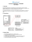
By default, the notifications regarding the back-up battery status are disabled. To enable/disable a certain notification, please refer to the following configuration methods. SMS text message content: BATCON:ON Example: BATCON:ON SMS text message content: Disable Battery Connected BATCON:OFF Notification Example: BATCON:OFF SMS text message content: Enable Battery Disconnected BATDIS:ON Notification Example: BATDIS:ON SMS text message content: Disable Battery BATDIS:OFF Disconnected Notification Example: BATDIS:OFF SMS text message content: Enable Low Battery BLOW:ON Notification Example: BLOW:ON SMS text message content: Disable Low Battery BLOW:OFF Notification Example: BLOW:OFF SMS text message content: Enable Mains Power Supply PWRLOST:ON Lost Notification Example: PWRLOST:ON SMS text message content: Disable Mains Power Supply PWRLOST:OFF Lost Notification Example: PWRLOST:OFF SMS text message content: Enable Mains Power Supply PWRREST:ON Restore Notification Example: PWRREST:ON SMS text message content: Disable Mains Power Supply PWRREST:OFF Restore Notification Example: PWRREST:OFF Enable Battery Connected Notification 8. System Information: Status SMS The system supports an informational SMS text message identified as the Status SMS, which can be delivered upon request. Once requested, the system will reply with Status SMS that may provide the following: System name System date & time GSM signal strength System’s internal temperature Name and status (ON/OFF) of the output Input Z1 state / value Input Z2 state / value SMS text message content: Request System Information STATUS Example: STATUS SMS text message content: TESTM:1;2;4;5;6;7;8 Value: 1 - system name; 2 - system date and time; 4 - GSM signal Manage Status SMS Content strength; 5 - system‘s internal temperature; 6 - name and status of the output; 7 - input Z1 state/value; 8 - input Z2 state/value. Example: TESTM:3;6;8;1;2 SMS text message content: Enable Periodic Status SMS TEST:frequen & Set Frequency Value: frequen – frequency, range – [1... 1193046] hours. Example: TEST:15550 SMS text message content: Disable Periodic Status SMS TEST:OFF Example: TEST:OFF GSM Module (E18SGGSM) Insatallation & User Manual 1. Overview The SmartGuard GSM Module uses the GSM network to transmit information coming from connected equipment to authorised users e.g. send alarm notification from an intruder alarm panel to a mobile phone. The SmartGuard GSM Module has two normally open digital inputs (zone1 & zone2).The SmartGuard GSM Module can also be used to send commands to electrical equipment e.g. remotely turn central heating on in a house from a mobile phone. The SmartGuard GSM Module has one open collector output. 2. Connections Battery must be rechargeable NiMH 9V 250mAh 48 x 26 x 15mm ANT FW TAMPER GSM MODEM RESET SIM CARD LED USB MIC -/+ F1 GSM antenna Pins for firmware update Tamper switch GSM network 900/1800 MHz modem Button for restoring default settings SIM card slot / holder Light-emitting diode indicating system status Mini USB port Microphone connector Backup battery slots 0.5A fuse LED Indication OFF Flashing every 30 ms Flashing every 0,5 sec. Flashing every 1 sec. Description No power supply SIM card is not present / PIN code enabled Searching for GSM network Connected to GSM network/system operating successfully Connectors Z1 COM Z2 DC C1 Description Digital input terminal Common terminal Digital input terminal/temperature sensor data terminal (DATA) Positive power supply terminal Open-collector output terminal/temperature sensor power supply terminal (+4V) 3. System Notes The GSM module should be fixed to a wall using 4 screws. Do not install the GSM unit onto metal as this will reduce signal strength. The SIM card’s PIN code must be disabled. Any SMS messages stored on the SIM card will be deleted during the system start-up. Power supply cables should be connected last when wiring (see 2. Connections). System start-up should take less than one minute. To manage input and/or tamper alarm and restore notifications by SMS text message, please refer to the following configuration methods: 4. Wiring Diagrams Disable Input Alarm Notification Enable Input Alarm Notification Set Input Alarm Text Disable Input Restore Notification 5. Date & Time The system comes equipped with internal real-time clock (RTC) that keeps track of the current date and time. Once the system is up and running, the user must set the correct date and time, otherwise the system will not operate properly. After shutting down and starting up the system, the date and time must be set again. Setting the Date & Time SMS text message content: CLK:yyyy.mm.dd_hr:mn Value: yyyy – year; mm – month, range – [01... 12]; dd – day, range – [01... 31]; hr – hours, range – [00... 23]; mn – minutes, range – [00... 59]. Example: CLK:2013.03.16_14:33 6. Operation a. Saving a user’s phone number to the SIM card using a phone call Only one user’s phone number can be saved to the SIM card in this manner. Insert the SIM card into the SmartGuard GSM Module and make a phone call to it from the phone number you wish to save as ‘User1’. NB: Caller ID must not be blocked. b. Changing users’ phone numbers on the SIM card using an SMS text message The user phone numbers can be changed by sending the SIM card an SMS text message from a phone number that is already saved in the GSM unit. To save the ‘User1’ phone number, send the SIM card an SMS text message in the following format: NR1:xxxxxxxxxx (where x = the user’s phone number). This process can be repeated for the ‘User2’ phone number by using the following format: NR2:xxxxxxxxxx. c. Reporting of triggered inputs When a digital input (zone1 or zone2) is triggered, the users are informed by an SMS text message containing the text ‘Triggered ZONE1’ or ‘Triggered ZONE2’. When a digital input is reset, the users are informed by an SMS text message containing the text ‘Restored ZONE1’ or ‘Restored ZONE2’. The text in these messages can be changed as follows: Enable Input Restore Notification Set Input Restore Text f. Triggering outputs The open collector output can be triggered by sending the GSM module an SMS text message from the saved ‘User1’ or ‘User2’ phone numbers. To turn the output on, the SMS text message sent should say OUT:ON. To turn the output off, the SMS text message sent should say OUT:OFF. g.Outputs By default, output C1 name is output. To rename the output, send the following SMS: Rename Output Turn ON Output SMS text message content: OUT:ON Example: OUT:ON Turn OFF Output SMS text message content: OUT:OFF Example: OUT:OFF h.Tamper The system comes equipped with on-board tamper switch designed for sabotage detection. In the event of enclosure tampering, the system can notify the user by SMS text message or phone call. Set Tamper Name SMS text message content: ZONE1:NC Example: ZONE1:NC Set Input Z1 as NO (normally open) SMS text message content: ZONE1:NO Example: ZONE1:NO Set Input Z2 as NC (normally closed) SMS text message content: ZONE2:NC Example: ZONE2:NC Set Input Z2 as NO (normally open) SMS text message content: ZONE2:NO Example: ZONE2:NO SMS text message content: TOUT:out-name Value: out-name - up to 23 characters output name Example: TOUT:Lamp To turn the output on or off: d. Inputs By default, the inputs are set as NO (normally open). To change the state of the inputs: Set Input Z1 as NC (normally closed) SMS text message content: SAZi:OFF Value: i - input number, range - [1...2] Example: SAZ1:OFF SMS text message content: SAZi:ON Value: i - input number, range - [1...2] Example: SAZ2:ON SMS text message content: TAZi:in-alarm-text Value: i - input number, range - [1...2]; in-alarm-text - up to 23 characters input alarm text Example: TAZ2:Alarm Z2 SMS text message content: SRZi:OFF Value: i – input number, range – [1... 2] Example: SRZ2:OFF SMS text message content: SRZi:ON Value: i – input number, range – [1... 2] Example: SRZ1:ON SMS text message content: TRZi:in-restore-text Value: i – input number, range – [1... 2]; in-restore-text – up to 23 characters input restore text Example: TRZ1:Restore Z1 Disable Tamper Alarm / Restore Notification Enable Tamper Alarm / Restore Notification SMS text message content: TTMP:tamp-name Value: tamp-name – up to 23 characters tamper name Example: TTMP:Tamper SMS text message content: TMP:OFF Example: TMP:OFF SMS text message content: TMP:ON Example: TMP:ON 7. Back-Up Battery and Mains Power Supply Status Monitoring The system may come equipped with a back-up battery maintaining the power supply of the system for up to 12 hours when the mains power supply is temporally lost. The implemented feature allows to perform a selftest on the backup battery every 6 seconds and notify the user by SMS text message under the following conditions: Battery connected – battery is present. Battery disconnected – battery is dead or missing. Low battery – battery voltage is 8V or lower.