1
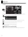
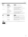
Reference Manual
This document describes menu items and messages of the V-800HD.
Copyright © 2012 ROLAND CORPORATION
All rights reserved. No part of this publication may be reproduced in any form without the written
permission of ROLAND CORPORATION.
* Roland is either registered trademark or trademark of Roland Corporation in the United States and/or other countries.
* All product names mentioned in this document are trademarks or registered trademarks of their respective owners.
2PS
Menu List
Press the [MENU] button on the top panel to call up the menu items. The menu will appear on the multi-view monitor connected
to the V-800HD.
* Press the [MENU] button again or the press the [EXIT] button to make the menu disappear.
fig.menu-display.eps
Setup Menu
Input
Output
Transition
PinP
Key
DSK
System
PVW
ENTER
ENTER
ENTER
ENTER
ENTER
ENTER
ENTER
PGM
CH 1
CH 2
CH 3
CH 4
CH 5
CH 6
CH 7
CH 8
The first level menu items (as below) are displayed at first. For detailed menu items and the values, refer to the following pages of
this document.
fig.1st-level-menu.eps
Input
Output
Transition
PinP
Key
DSK
System
This is for input setup like source assign etc.
This is for output setup like format selection etc.
This is for transition setup.
This is for Picture in Pictue setup.
This is for luminace and chroma key setup.
This is for DSK setup.
This is for system setup of the V-800HD.
The values in [ ] are the factory default values of the V-800HD. Hold down [ENTER] button and press [EXIT] button to make the value return to
default.
You can also change a setting value up or down by 10 units by holding down the [ENTER] button and turning the [VALUE] dial.
"
1.5
" marks are inscribed on the function which became an addition from the version 1.5.
For information about version1.50 software, download from the following Roland website.
http://www.rolandsystemsgroup.net/
1.5 Supports Multi-view monitor not compatible with HDCP
• As the multi-view monitor, now you can connect HDCP non-compatible product.
• However, of HDCP of the V-800HD is turned on, the multi-view screen is filled with plain blue. It can display the menu screen
only.
2
Menu List
Input Menu
Item
Display/Value
Explanation
Ch.1 - Ch.4
No Signal,
This part displays the current input format.
[email protected] [email protected]
Ch.5 - Ch.8
[3G/HD/SD-SDI],
This part displays the currently selected input jack.
Composite,
You cannot select [Shared Input] for Ch.1.
Shared Input
When the menu is not displayed, you can switch this setting by
pressing [MENU]+[PST/EFFECT].
No Signal,
This part displays the current input format.
[email protected] -
[HDCP] is displayed while signal with HDCP is input.
[email protected]
[DVI-D/HDMI] or [DVI-A],
This part displays the currently selected input jack.
RGB/Component,
You cannot select [Shared Input] for Ch.5.
Shared Input
When the menu is not displayed, you can switch this setting by
pressing [MENU]+[PST/EFFECT].
* The displayed jack name differs depending on the switch position on rear panel. If you are selecting DVI-D, [DVI-D/HDMI] is displayed. If you
switch to DVI-A, the display will be [DVI-A].
Item
Display/Value
Explanation
Ch.9
Memory No.1,
Still Image
This part shows the currently selected memory No. of still
images.
When the menu is not displayed, you can switch this setting by
pressing [MENU]+[PST/EFFECT].
Ch.10
R:16 G:16 B:16
[Background],
Still Image
This part shows either the color values of the background color
or the memory number of the currently assigned background
image.
When the menu is not displayed, you can switch this setting by
pressing [MENU]+[PST/EFFECT].
If the [ENTER] mark is displayed on top of the menu screen, you can move to lower levels by pressing the [ENTER] button. Change setup values on
lower levels.
fig.enter-mark.eps
3
Menu List
Detailed setup of Ch.1 - Ch.4 (3G/HD/SD-SDI, Composite, Shared Input)
Item
Display/Value
Explanation
Scaling
Zoom
Type
You can change scaling settings with items below.
10% - [100%] - 1000%
This sets the zoom ratio.
[Full], Letterbox, Crop,
This selects the scaling type.
Dot by Dot, Manual
The scaling type changes as described below:
Full : The input image will be displayed fully on output screen.
The aspect ratio will be changed.
Letterbox : The entirety of the input image will be displayed on
output screen. The aspect ratio will be maintained.
Crop : The input image will be displayed fully on the output
screen. The aspect ratio will be maintained.
Dot by Dot : Scaling will not be executed.
Manual : The scaling will be executed depending on the
manual settings below.
Manual Size H
-2000 - [0] - +2000
This sets the horizontal size.
Manual Size V
-2000 - [0] - +2000
This sets the vertical size.
Position H
-1920 - [0] - +1920
This sets the horizontal position.
Position V
-1200 - [0] - +1200
This sets the vertical position.
* Depending on the input/output format settings, the range of value settings will be altered. The values above are the minimum/maximum values.
Color Correction
You can change color correction settings with items below.
Brightness
-64 - [0] - +63
This adjusts the brightness.
Contrast
-64 - [0] - +63
This adjusts the contrast.
Saturation
-64 - [0] - +63
This adjusts the color saturation.
Red
-64 - [0] - +63
This adjusts the red level.
Green
-64 - [0] - +63
This adjusts the green level.
Blue
-64 - [0] - +63
This adjusts the blue level.
Detailed setup of Ch.5 - Ch.8 (DVI-D/HDMI)
Item
Display/Value
Explanation
Color Space
This selects the color space.
[Auto],
RGB(0-255), RGB(16-235),
YCC(SD), YCC(HD)
Flicker Filter
ON, [OFF]
This turns on/off the flicker filter.
Scaling
You can change scaling settings. (same as Ch.1 - Ch.4)
Color Correction
You can change color correct settings. (same as Ch.1 - Ch.4)
Detailed setup of Ch.5 - Ch.8 (DVI-A, RGB/Component)
Item
Display/Value
Explanation
Color Space
This selects the color space.
[Auto],
RGB(0-255), RGB(16-235),
YCC(SD), YCC(HD)
Flicker Filter
ON, [OFF]
This turns on/off the flicker filter.
Scaling
You can change scaling settings. (same as Ch.1 - Ch.4)
Color Correction
You can change color correct settings. (same as Ch.1 - Ch.4)
Sampling
Auto Sampling
You can change sampling settings with items below.
Execute
Press [ENTER] button to execute auto sampling setup.
Position H
-1920 - [0] - +1920
This sets the horizontal start position of sampling.
Position V
-1200 - [0] - +1200
This sets the vertical start position of sampling.
Frequency
-128 - [0] - +127
This sets the sampling frequency.
Phase
-128 - [0] - +127
This sets the sampling phase.
* Depending on the input/output format settings, the range of value settings will be altered. The values above are the minimum/maximum values.
4
Menu List
Detailed setup of Ch.5 - Ch.8 (Shared Input)
Item
Display/Value
Explanation
Scaling
You can change scaling settings. (same as Ch.1 - Ch.4)
Color Correction
You can change color correct settings. (same as Ch.1 - Ch.4)
Detailed setup of Ch.9 - Ch.10 (Still Image)
Item
Display/Value
Explanation
Still Image Memory No.
[1] - 16
This selects the memory No. of still images. The loaded number
is displayed with [*].
Position H
-1920 - [0] - +1920
This sets the horizontal display position.
Position V
-1200 - [0] - +1200
This sets the vertical display position.
* Depending on the input/output format settings, the range of value settings will be altered. The values above are the minimum/maximum values.
Color Correction
You can change color correct settings. (same as Ch.1 - Ch.4)
Detailed setup of Ch.10 (Background)
Item
Display/Value
Explanation
Color
You can change the background color setting with R/G/B values.
Red
0 - [16] - 255
This adjusts the red level.
Green
0 - [16] - 255
This adjusts the green level.
Blue
0 - [16] - 255
This adjusts the blue level.
5
Menu List
Output Menu
Item
Display/Value
Format
Explanation
You can change output format settings with items below.
Main
480i4:3 - [1080i] - WUXGA
This selects the main output format.
RGB/Component
480p4:3 - [SXGA] - WUXGA
This selects the RGB/Component output format.
Composite
[480i4:3/576i4:3],
* Interlaced output is not available.
This selects the Composite output format.
480i16:9, 576i16:9
1.5 AUX Source
Mixer Input, Mixer Output,
This selects the signal to be sent to the AUX bus
DSK Source, DSK Output,
You can directly send the input channel signal to the AUX bus.
Input CH.1, ... Input CH.10
However, you cannot use DSK while you are selecting input
signal.
Source Assign
You can assign the signal bus to various output jacks.
If an HDCP connection is found, [HDCP] appears of the left side
of the jack name.
The format in the parentheses () represents the currently
selected output format. If this is blank, no signal is currently
being output.
SDI 1
[PGM], PVW, AUX
This selects the bus to be sent to SDI 1 jack.
SDI 2
PGM, [PVW], AUX
This selects the bus to be sent to SDI 2 jack
DVI-D/HDMI 1
[PGM], PVW, AUX
This selects the bus to be sent to DVI-D/HDMI 1 jack.
DVI-D/HDMI 2
PGM, [PVW], AUX
This selects the bus to be sent to DVI-D/HDMI 2 jack.
RGB/Component
[PGM], PVW, AUX
This selects the bus to be sent to RGB/Component jack.
Composite
[PGM], PVW, AUX
This selects the bus to be sent to Composite jack.
* Only the common bus can be selected for RGB/Component jack and Composite jack. Individual selection is not possible.
HDMI
6
[Multi-view]
The output format for Multi-view monitor is fixed.
Menu List
Detailed setup of Main
Item
Display/Value
Explanation
Scaling
You can change scaling settings with items below.
Zoom
10% - [100%] - 1000%
This sets the zoom ratio.
Size H
-2000 - [0] - +2000
This sets the horizontal size.
Size V
-2000 - [0] - +2000
This sets the vertical size.
Position H
-1920 - [0] - +1920
This sets the horizontal position.
Position V
-1200 - [0] - +1200
This sets the vertical position.
* Depending on the input/output format settings, the range of value settings will be altered. The values above are the minimum/maximum values.
Cropping
Orientation
You can change cropping settings with items below.
[Upper Left], Upper Right,
This sets the orientation of cropping.
Lower Left, Lower Right,
Center
Type
[Full], 4:3, 5:4, 16:9,
This selects the cropping type from below.
Manual
Full : When the Zoom value is 100%, the entirety of the image is
shown on the output screen.
4:3, 5:4, 16:9 : The image will be cropped according to the
selected aspect ratio. If the Zoom value is 100%, the image will
be letterboxed.
Manual : The image will be cropped according to the values
below.
Manual Size H
0 - [128] - 2000
This sets the horizontal size.
Manual Size V
0 - [128] - 2000
This sets the vertical size.
* Depending on the input/output format settings, the range of value settings will be altered. The values above are the minimum/maximum values.
1.5 Color Correction
You can change color correct settings with items below.
The range of color correction is expanded.
Brightness
-128 - [0] - +127
This adjusts the brightness.
Contrast
-128 - [0] - +127
This adjusts the contrast.
Saturation
-128 - [0] - +127
This adjusts the color saturation.
Red
-64 - [0] - +63
This adjusts the red level.
Green
-64 - [0] - +63
This adjusts the green level.
Blue
-64 - [0] - +63
This adjusts the blue level.
1.5 3G-SDI Mapping
Level A, Level B
The V-800HD ver. 1.5 supports level B mapping structure of 3GSDI (1080p50Hz, 1080p59.94Hz).The 3G-SDI mapping structure
of the input signal is detected automatically.The mapping
structure of 3G-SDI output signal can be selected using the
menu.
DVI-D/HDMI
You can change settings related to the DVI-D/HDMI output jack.
Output 1
Signal Mode
Color Space
You can change settings of the DVI-D/HDMI output 1.
[DVI-D], HDMI
This selects the output mode.
[RGB(0-255)], RGB(16-235),
This selects the color space.
YCC(444), YCC(422)
Output 2
Signal Mode
Color Space
You can change settings of the DVI-D/HDMI output 2.
[DVI-D], HDMI
This selects the output mode.
[RGB(0-255)], RGB(16-235),
This selects the color space.
YCC(444), YCC(422)
7
Menu List
Detailed setup of RGB/Component
Item
Display/Value
Explanation
Color Space
This selects the color space.
[Auto],
RGB(0-255), RGB(16-235),
YCC(SD), YCC(HD)
8
Scaling
You can change scaling settings. (same as Main)
Color Correction
You can change color correct settings. (same as Main)
Detailed setup of Composite
Item
Display/Value
Explanation
Scaling
You can change scaling settings. (same as Main)
Color Correction
You can change color correct settings. (same as Main)
Menu List
Transition Menu
Item
Display/Value
Explanation
Time
0.0s - [1.0s] - 10.0s,
0s0f - 10s0f,
This sets the transition time. The displayed value differs
depending on system frame rate and the Unit setup.
0f - 300f
Unit
[Seconds],
This selects the time unit to be displayed.
Seconds.Frames, Frames
Wipe Pattern
1 - 7, [MIX]
This selects the transition type.
Detailed setup of Wipe Pattern 1 - 7
Select one from [1] to [7] and press [ENTER] to execute the detailed setup as below.
Item
Display/Value
Explanation
Pattern
Horizontal, Vertical,
This selects the wipe pattern.
Horizontal Open, Vertical Open,
Upper Left, Upper Right,
Lower Left, Lower Right, Box
The factory default setting of Wipe Pattern buttons [1] - [7] are as below.
1 Horizontal
2 Vertical
3 Upper Left
4 Upper Right
5 Lower Left
6 Lower Right
7 Box
Direction
[Normal], Reverse, N/R
Border
This selects the wipe direction.
You can change border settings with items below.
Width
[0] - 63
This sets the border width.
Red
0 - [128] - 255
This sets the red level of border color.
Green
0 - [128] - 255
This sets the green level of border color.
Blue
0 - [128] - 255
This sets the blue level of border color.
9
Menu List
PinP Menu
Item
Display/Value
Explanation
Status
[OFF], PVW, PGM
Select output status of PinP from below.
Position
1-4
OFF
No display.
PVW
Display on PVW output.
PGM
Display on PGM output.
Select one of the Positions [1] - [4] and press the [ENTER] button
to execute the detailed setup.
Detailed setup of Position 1 - Position 4
Item
Display/Value
Explanation
PinP
You can change settings of PinP buttons [1] - [4].
Size
-10% - [30%] - +100%
This sets the size of the inset screen.
Position H
-100% - +100%
This sets the horizontal position of the inset screen.
Position V
-100% - +100%
This sets the vertical position of the inset screen.
[Original], 4:3, 5:4, 16:9,
This selects the cropping type of the inset screen.
Cropping Type
Manual
Manual Cropping H
-2000 - [0] - +2000
This sets the horizontal cropping width.
Manual Cropping V
-2000 - [0] - +2000
This sets the vertical cropping width.
* Manual cropping is valid when [Manual] is selected as
Cropping Type.
Border
Width
You can change settings of PinP border with items below.
0 - [5] - 63
Color
This sets the border width.
Border color can be set with items below.
Red
0 - [128] - 255
This sets the red level of border color.
Green
0 - [128] - 255
This sets the green level of border color.
Blue
0 - [128] - 255
View
This sets the blue level of border color.
You can zoom in/out or change view position of the image in
inset screen.
Size
10% - [100%] - 1000%
This sets the zoom ratio.
Position H
-1920 - [0] - +1920
This sets the horizontal view position.
Position V
-1200 - [0] - +1200
This sets the vertical view position.
* Depending on the input/output format settings, the range of value settings will be altered. The values above are the minimum/maximum values.
The factory default settings of PinP buttons [1] through [4] are as below.
• 1 : Position H : -25%, Position V : -25%
• 2 : Position H : +25%, Position V : -25%
• 3 : Position H : -25%, Position V : +25%
• 4 : Position H : +25%, Position V : +25%
10
Menu List
Key Menu
Item
Display/Value
Explanation
Status
[OFF], PVW, PGM
Select output status of Key composition from below.
Mode
[Self key], External Key
OFF
Not display.
PVW
Display on PVW output.
PGM
Display on PGM output.
This selects the key mode.
Detailed setup of Self Key
Item
Display/Value
Explanation
Type
This selects the extraction color.
Luminance 1 (White),
[Luminance 2 (Black)],
Chroma 1 (Blue),
Chroma 2 (Green)
Luminance 1 (White) : This extracts the brighter area of the image.
Luminance 2 (Black) : This extracts the darker area of the image.
Chroma 1 (Blue) : This extracts the blue area of the image.
Chroma 2 (Green) : This extracts the green area of the image.
Level
0 - [32] - 255
1.5 Hue
This sets the amount of extraction.
This adjusts the extraction color. This is valid when [Chroma 1] or
[Chroma 2] is selected as the Type.
The extraction color was fixed to blue or green in previous
version. Now it’s possible to fine adjust the color.
Fine
-128 - +127
This sets the center value of the hue adjustment.
Width
-128 - +127
This sets the width of the hue adjustment.
Saturation
-128 - [0] - +127
This adjusts the saturation of the extraction color. This is valid
when [Chroma 1] or [Chroma 2] is selected as the Type.
[0] - 255
This sets the amount of edge blur.
(This affects same as previous hue setting).
Gain
Detailed setup of External Key
Item
Display/Value
Explanation
Type
This selects the extraction color.
Key Coupling
White, [Black]
Fill - Source
This sets the external key source for each key fill channels.
Ch.1
Ch.1 - [Ch.8] - Ch.10
This sets the external key source channel when the key fill is Ch.1.
Ch.2
Ch.1 - [Ch.8] - Ch.10
This sets the external key source channel when the key fill is Ch.2.
Ch.3
Ch.1 - [Ch.8] - Ch.10
This sets the external key source channel when the key fill is Ch.3.
Ch.4
Ch.1 - [Ch.8] - Ch.10
This sets the external key source channel when the key fill is Ch.4.
Ch.5
Ch.1 - [Ch.8] - Ch.10
This sets the external key source channel when the key fill is Ch.5.
Ch.6
Ch.1 - [Ch.8] - Ch.10
This sets the external key source channel when the key fill is Ch.6.
Ch.7
Ch.1 - [Ch.8] - Ch.10
This sets the external key source channel when the key fill is Ch.7.
Ch.8
Ch.1 - [Ch.8] - Ch.10
This sets the external key source channel when the key fill is Ch.8.
Ch.9
Ch.1 - [Ch.8] - Ch.10
This sets the external key source channel when the key fill is Ch.9.
Ch.10
Ch.1 - [Ch.8] - Ch.10
This sets the external key source channel when the key fill is Ch.10.
11
Menu List
DSK Menu
Item
Display/Value
Explanation
PGM Output
[OFF], ON
This turns on/off the PGM output of DSK.
PVW Output
[OFF], ON
This turns on/off the PVW output of DSK.
Type
Luminance 1 (White),
This selects the extraction color.
[Luminance 2 (Black)],
Chroma 1 (Blue),
Chroma 2 (Green)
Luminance 1 (White) : This extracts the brighter area of the image.
Luminance 2 (Black) : This extracts the darker area of the image.
Chroma 1 (Blue) : This extracts the blue area of the image.
Chroma 2 (Green) : This extracts the green area of the image.
Level
0 - [32] - 255
1.5 Hue
This sets the amount of extraction.
This adjusts the extraction color. This is valid when [Chroma 1] or
[Chroma 2] is selected as the Type.
The extraction color was fixed to blue or green in previous
version. Now it’s possible to fine adjust the color.
Fine
-128 - +127
Width
-128 - +127
This sets the center value of the hue adjustment.
This sets the width of the hue adjustment.
(This affects same as previous hue setting).
Saturation
-128 - [0] - +127
This adjusts the saturation of the extraction color. This is valid
when [Chroma 1] or [Chroma 2] is selected as the Type.
Gain
[0] - 255
This sets the amount of edge blur.
Source Channel
1 - [8] - 10
This selects the channel to overlay for DSK composition.
When the External Key is valid, you cannot use the DSK. Turn the [Mode] to [Self Key] in Key menu.
12
Menu List
System Menu
Item
Display/Value
Explanation
HDCP
[OFF], ON
This turns on/off the HDCP mode. A confirmation screen appears
when [ON] is selected.
Color Space
RGB, [YCC]
This selects the color space.
NTSC Setup Level
[0IRE], 7.5IRE
This selects the NTSC setup level.
[59.94Hz], 50Hz
This selects the system frame date of the V-800HD.
Internal, External,
This selects the sync mode of the V-800HD.
Frame Rate
1.5 Reference
Input SDI 1, ... Input SDI 4 *1
The V-800HD ver. 1.50 can synchronize with SDI input as
reference.You can select a reference SDI input.
Clock Adjust
-1920 - [0] - +1920 *2
This adjust the sync clock when [External] is selected.
Line Adjust
-1200 - [0] - +1200
This adjusts the line position when [External] is selected.
1.5 Field Sync Processing
While the V-800HD input/output interlaced signals,
synchronization of fields is possible.
ON
Enables the field sync processing.The fields of input/output
match and this improves the image quality.
However, the processing time increases.
OFF
1.5 Panel Operation
PGM/PST, A/B
PGM/PST is the default mode.Regardless to the PGM section or
PST/EFFECT section of cross-points, PGM is determined by the
video fader position. The indicator of the PGM output channel
lights in red. The indicator of the PST output channel lights in
green.While you are compositing images, the indicator of
background channel lights in red. The indicator of foreground
channel lights in green.
Output Capture
Press [ENTER] to execute detailed setup of still image capture.
Output Fade
Press [ENTER] to execute detailed setup of output fade.
Multi-view Label
Press [ENTER] to execute detailed setup of multi-view labels.
Cross-point Assign
Press [ENTER] to execute detailed setup of channel assign to
cross-points.
Remote
[OFF], ON
This selects valid/invalid of remote control from an external RS232C device.
MIDI
Press [ENTER] to execute detailed setup of MIDI.
1.5 Memory Recall Parameters
You can select the parameters to recall when you operate the
MEMORY buttons.
ALL
This recalls all the parameters (same as previous version)
Cross-point
This recalls the parameters below only.
- Channel selection
- Key setup
- PinP setup
- DSK setup
- Wipe setup
- Input connector selection
* 1 : The output vsync of the V-800HD synchronizes with the input signal when the value of System -> Reference is Input SDI 1, ... Input SDI 4. In this
case, the system latency is minimized. If you want to synchronize the input/output fields, execute the settings below.
Turn the Field Sync Processing of System to ON
Although the processing time increases, the input/output fields
match automatically.
Adjust the value of Reference Line Adjust in System
Although the input/output phases differ, you can minimize the
latency keeping the synchronization of input/output fields.
* 2 : Depending on the input/output format settings, the range of value settings will be altered. These values are the minimum/maximum.
13
Menu List
Memory Switch Fade
[OFF], ON
This turns on/off the output fade during memory loading.
Memory Protect
[OFF], ON
This turns on/off the memory protection.
1.5 Auto Memory
ON, OFF
If this is turned on, the current status of the V-800HD is saved to
memory 1-1 automatically. The status is loaded at next booting
and the status returns.
The auto saving is carried out when you operate any menu
cursor. Auto saving does not work when cross-point buttons or
video fader is operated.
USB Memory
You can change settings related to USB memory with items below.
Parameter
Press [ENTER] to execute detailed setup of saving to/loading
from USB memory.
Still Image
Press [ENTER] to execute detailed setup of still image loading.
Format
This executes formatting of a connected USB memory.
A confirmation screen appears if you press [ENTER] while
[Execute] is displayed.
Still Image Delete
This deletes the still images saved to internal memory of the V-800HD.
Video Fader Calibrate
Press [ENTER] while [Execute] is displayed to calibrate the video fader.
LED Dimmer
0 - [7]
This adjusts the brightness of the top panel LEDs.
Menu Background
0 - [4] - 7
This adjust the transparency of the menu background.
Menu Position
[Left], Right
This switches the position of menu display. You can also switch
with [MENU] + [CURSOR]. Hold down [MENU] and press left/right
[CURSOR].
Test Pattern
[OFF], ColorBar75%,
This selects the test pattern.
ColorBar100%, Ramp,
Step, Hatch, Frame,
Frame (PVW)
Factory Reset
1.5 System Information
This makes the V-800HD to return to factory default setting.
A confirmation screen appears if you press [ENTER] while
[Execute] is displayed.
You can check the version number in System menu of the
V-800HD.
The memory saved settings is not compatible with the previous version. At the first booting after update, factory reset is executed automatically.
14
Menu List
Detailed setup of MIDI
Item
Status
Display/Value
Explanation
OFF, [Native], V-LINK Master,
This selects the MIDI remote control mode.
V-LINK Slave, MVC Slave
OFF : No communication via MIDI.
Native : Communicate using standard MIDI mode.
V-LINK Master : Communicate as the V-Link master device.
V-LINK Slave : Communicate as the V-Link slave device.
MVC Slave : Communicate as the MVC(MIDI Visual Control) slave
device.
* If the V-800HD receives message from an external V-Link/MVC master device while [Native] is selected, the mode automatically turns to V-Link
Slave or MVC Slave.
Through Output
[OFF], ON
This turns on/off of through output of the MIDI OUT/THRU jack.
Channel
[1] - 16
This selects the MIDI channel to be used in standard MIDI mode.
Detailed setup of Output Capture
You cannot use the output capture if you are selecting [Fade to Still Image] in [Output Fade] or selecting [Still Image] as the source of Ch.10.
Item
Display/Value
Explanation
Source Bus
[PGM], PVW, AUX
This selects the source bus for still image capture. Image of the
selected bus is displayed in PGM area of the multi-view monitor.
Destination
Still Image
Memory No.
This selects the internal memory number for still image.
[1] - 16
The numbers already used are displayed with [*].
A confirmation screen appears if you press [ENTER] while
[Execute] is displayed.
15
Menu List
Detailed setup of Output Fade
Item
Display/Value
Explanation
Mode
This selects the mode of output fade.
[Fade to Background],
Fade to Still Image,
Output Freeze
Fade to Background
Item
Display/Value
Explanation
Time
0.0s - [0.5s] - 10.0s
This adjusts the fade time.
Color Setting
Red
You can set the color with items below.
0 - [16] - 255
This sets the red level.
Green
0 - [16] - 255
This sets the green level.
Blue
0 - [16] - 255
This sets the blue level.
Item
Display/Value
Explanation
Time
0.0s - [0.5s] - 10.0s
This adjusts the fade time.
Still Image
[1] - 16
This selects the internal memory number.
Position H
-1920 - [0] - +1920
This adjust the horizontal display position.
Position V
-1200 - [0] - +1200
This adjusts the vertical display position.
Fade to Still Image
Memory No.
* Depending on the input/output format settings, the range of value settings will be altered. These values are the minimum/maximum.
Color Correction
16
You can execute color correction with items below.
Brightness
-64 - [0] - +63
This adjusts the brightness.
Contrast
-64 - [0] - +63
This adjusts the contrast.
Saturation
-64 - [0] - +63
This adjusts the saturation.
Red
-64 - [0] - +63
This adjusts the red level.
Green
-64 - [0] - +63
This adjusts the green level.
Blue
-64 - [0] - +63
This adjusts the blue level.
Menu List
Detailed setup of Multi-view Label
Item
Display/Value
Explanation
Indicate
OFF, [ON]
This turns on/off the display of labels and green/red borders.
Label
PVW
PGM
Ch.1 SDI
Ch.1 Composite
Ch.2 SDI
Ch.2 Composite
Ch.2 Shared Input
Ch.3 SDI
Ch.3 Composite
Ch.3 Shared Input
Ch.4 SDI
Ch.4 Composite
Ch.4 Shared Input
Ch.5 DVI-I
Ch.5 RGB/Component
[“PVW”]
[“PGM”]
[“CH.1 SDI”]
[“CH.1 CMP”]
[“CH.2 SDI”]
[“CH.2 CMP”]
[“CH.2 SHR”]
[“CH.3 SDI”]
[“CH.3 CMP”]
[“CH.3 SHR”]
[“CH.4 SDI””]
[“CH.4 CMP”]
[“CH.4 SHR”]
[“CH.5 DVI”]
[“CH.5 RGB”]
Ch.6 DVI-I
Ch.6 RGB/Component
[“CH.6 DVI”]
[“CH.6 RGB”]
Ch.6 Shared Input
Ch.7 DVI-I
Ch.7 RGB/Component
[“CH.6 SHR”]
[“CH.7 DVI”]
[“CH.7 RGB”]
Ch.7 Shared Input
Ch.8 DVI-I
Ch.8 RGB/Component
[“CH.7 SHR”]
[“CH.8 DVI”]
[“CH.8 RGB”]
Ch.8 Shared Input
Ch.9 Still Image
Ch.10 Still Image
Ch.10 Background
[“CH.8 SHR”]
[“CH.9 STL”]
[“CH10 STL”]
[“CH10 BG”]
Press [ENTER] to display the label editing screen of PVW.
Press [ENTER] to display the label editing screen of PGM.
Press [ENTER] to display the label editing screen of Ch.1 (SDI).
Press [ENTER] to display the label editing screen of Ch.1 (Composite).
Press [ENTER] to display the label editing screen of Ch.2 (SDI).
Press [ENTER] to display the label editing screen of Ch.2 (Composite).
Press [ENTER] to display the label editing screen of Ch.2 (Shared Input).
Press [ENTER] to display the label editing screen of Ch.3 (SDI).
Press [ENTER] to display the label editing screen of Ch.3 (Composite).
Press [ENTER] to display the label editing screen of Ch.3 (Shared Input).
Press [ENTER] to display the label editing screen of Ch.4 (SDI).
Press [ENTER] to display the label editing screen of Ch.4 (Composite).
Press [ENTER] to display the label editing screen of Ch.4 (Shared Input).
Press [ENTER] to display the label editing screen of Ch.5 (DVI-I).
Press [ENTER] to display the label editing screen of Ch.5 (RGB/
Component).
Press [ENTER] to display the label editing screen of Ch.6 (DVI-I).
Press [ENTER] to display the label editing screen of Ch.6 (RGB/
Component).
Press [ENTER] to display the label editing screen of Ch.6 (Shared Input).
Press [ENTER] to display the label editing screen of Ch.7 (DVI-I).
Press [ENTER] to display the label editing screen of Ch.7 (RGB/
Component).
Press [ENTER] to display the label editing screen of Ch.7 (Shared Input.
Press [ENTER] to display the label editing screen of Ch.8 (DVI-I).
Press [ENTER] to display the label editing screen of Ch.8 (RGB/
Component).
Press [ENTER] to display the label editing screen of Ch.8 (Shared Input).
Press [ENTER] to display the label editing screen of Ch.9 (Still Image).
Press [ENTER] to display the label editing screen of Ch.10 (Still Image).
Press [ENTER] to display the label editing screen of Ch.10 (Background).
17
Menu List
Detailed setup of Cross-point Assign
Item
Display/Value
Explanation
Cross-point
1
[Ch.1] - Ch.10, None
This selects the input channel to be assigned to Cross-point 1.
2
Ch. 1 - [Ch.2] - Ch.10, None
This selects the input channel to be assigned to Cross-point 2.
3
Ch. 1 - [Ch.3] - Ch.10, None
This selects the input channel to be assigned to Cross-point 3.
4
Ch. 1 - [Ch.4] - Ch.10, None
This selects the input channel to be assigned to Cross-point 4.
5
Ch. 1 - [Ch.5] - Ch.10, None
This selects the input channel to be assigned to Cross-point 5.
6
Ch. 1 - [Ch.6] - Ch.10, None
This selects the input channel to be assigned to Cross-point 6.
7
Ch. 1 - [Ch.7] - Ch.10, None
This selects the input channel to be assigned to Cross-point 7.
8
Ch. 1 - [Ch.8] - Ch.10, None
This selects the input channel to be assigned to Cross-point 8.
9
Ch. 1 - [Ch.9] - Ch.10, None
This selects the input channel to be assigned to Cross-point 9.
10
Ch. 1 - [Ch.10], None
This selects the input channel to be assigned to Cross-point 10.
Detailed setup of USB Memory Parameter
Item
Display/Value
Explanation
Load
Press [ENTER] to display the screen to select a file to load.
Save
Press [ENTER] to display the screen to select a file to save.
Save As
Press [ENTER] to display the screen to edit the file name.
Delete
Press [ENTER] to display the screen to select a file to delete.
Detailed setup of USB Memory Still Image
Item
Display/Value
Explanation
Still Image Memory No.
This selects the internal memory number for still image loading.
[1] - 16
Load
Detailed setup of Still Image Delete
Item
Display/Value
Explanation
Still Image Memory No.
This selects the internal memory number for still image deleting.
Execute
18
Press [ENTER] to display the screen to select a file to load.
[1] - 16
Press [ENTER] while [Execute] is displayed to delete the still
image.
List of Messages
Processing.
This is displayed while this unit is processing data (still image loading, output capture etc.) Do not turn off power while this
message is displayed.
Push ENTER to execute.
This is displayed in case confirmation is necessary before execution (formatting USB memory etc.) Press [ENTER] to execute or
[EXIT] to cancel.
Set at upper (lower) position and push ENTER.
This is displayed when you execute video fader calibrations. Move the fader all the way to upper (or lower) side and press [ENTER].
USB memory is not ready.
This is displayed if the V-800HD cannot recognize USB memory.
File not found.
This is displayed if the connected USB memory does not contain files that can be recognized by the V-800HD.
File exists.
This is displayed if a same named file exists.
Cannot write file.
This is displayed if the V-800HD cannot properly write the file.
Cannot read file.
This is displayed if the V-800HD cannot properly read the file.
illegal file format.
This is displayed when you attempt to load a file that cannot be handled on the V-800HD. It is possible that the file is damaged.
Turn off [DSK].
This is displayed if you select [External Key] as key mode while the DSK output is in progress. Turn off DSK.
[External Key] mode. [DSK] is not available.
This is displayed when you enter DSK menu while the External Key is valid. Switch to [Self Key] in key mode.
Select [Fade to Background] in [Output Fade] at first.
This is displayed when you attempt to select [Still Image] for ch.10 or to execute output capture. If you want to execute these,
select [Background] in [Output Fade] at first.
Select [Background] for [Input Ch.10] at first.
This is displayed when you perform the following:
• Selecting [Fade to Still Image] or [Output Freeze] for output fade
• Executing output capture
If you want to do these things, select [Background] for Ch.10 source.
DVI output will be continued. Others will be stopped. Push ENTER to execute.
This is displayed when you turn on HDCP. If you turn it on, output from SDI, SD and RGB/Component will be stopped. Press
[ENTER] to turn it on. Press [EXIT] to cancel.
Signal with HDCP cannot be input. Push ENTER to execute.
This is displayed when you turn off HDCP. If you turn it off, processing of HDCP material will be terminated. Press [ENTER] to turn it
off. Press [EXIT] to cancel.
Fan error
This is displayed when the V-800HD detected error of cooling fan. Contact the nearest Roland Service Center, or an authorized
Roland distributor.
19