Download Compact, High Efficiency, 30 W Reference Platform, Supporting

Transcript
NCP1083WIRGEVB
Compact, High Efficiency,
30W Reference Platform,
Supporting Wide Auxiliary
Input Voltage, with the
NCP1083 Evaluation Board
User's Manual
http://onsemi.com
EVAL BOARD USER’S MANUAL
Board Details
The NCP1083WIRGEVB implements a PoE module
DC/DC converter that converts the higher voltage one the
Ethernet cable to a lower voltage (12 V) with power levels
up to 30 W. Detection, classification and power up sequence
is implemented according to IEEE802.3at (D4). The board
also supports getting its power from and auxiliary input, in
case PoE network is not available. Auxiliary input voltage
may be as low as 9 V. The isolated flyback DC/DC converter
design is optimized to support a very wide input voltage
range (9 V to 57 V) without compromising the overall
efficiency.
Figure 1. Front Side of EVB
Warnings
Close to the switching MOSFET voltages on the board
may exceed 200 V (@250 kHz). Temperature of board and
its components may exceed 85C during normal operation.
The Evaluation board was designed to operate correctly
under these conditions.
The input voltage should never exceed 57 V nor should
the evaluation board be loaded for long duration with loads
higher than the specified 30 W. Exceeding the specified
input and output values could permanently damage the
board.
Figure 2. Back Side of EVB
Table 1. EVALUATION BOARD SPECIFICATIONS
Min
Typ
Max
Unit
Input Voltage, PoE Input
Characteristic
36
−
57
V
Input Voltage, Auxiliary Input
9
−
57
V
Output Voltage
−
12
−
V
Output Current
−
−
2.5
A
Oscillator Frequency
−
250
−
kHz
Output Ripple
−
−
170
mV
Efficiency
−
−
86
%
 ON Semiconductor Components Industries, LLC, 2012
January, 2012 − Rev. 1
1
Publication Order Number:
EVBUM2029/D
NCP1083WIRGEVB
Table 2. BOARD CONNECTOR DESCRIPTION
Connector
Pin
Description
P1
1
nClassAT, notification towards external processor that IEEE802.3at, 2nd event classification has completed
2
Not Connected
3
VIN, PoE, Pair 1
4
VIN, PoE, Pair 1
5
VIN, PoE, Pair 2, High Efficiency Input Rectifier
6
VIN, PoE, Pair 2, High Efficiency Input Rectifier
JOUT
7, 8
VAUX, Positive Auxiliary Input Supply
9, 10
VAUX_GND, Auxiliary Input Supply Ground
1
12 V Regulated Output
2
12 V Regulated Output
3
12 V Regulated Output
4
GND Regulated Output
5
GND Regulated Output
6
GND Regulated Output
Powering Up and Testing the PoE DC/DC Converter
1. Connect a load to the output connector Jout (1, 2, 3) is +12 V and Jout (4, 5, 6) is ground. The load may range from
0 to 30 W.
2. When using the Power over Ethernet input, connect a lab supply or IEEE802.3at compliant PSE equipment to one of
the power over Ethernet inputs pair connections:
 Between connector P1, pin 3 and 4 for regular efficiency (polarity can be chosen freely).
 Between connector P1, pin 5 and 6 for increased efficiency (polarity can be chosen freely).
3. When using the auxiliary input, connect a lab supply (or any other available DC source) to connector P1, pin 7, 8 for
the positive node and pin 9, 10 for ground.
4. The DC/DC converter shall start working as soon as detection and classification is completed in PoE powered mode
or as soon as power is applied on the auxiliary input.
5. Measure the output voltage to be 12 V and that ripple or noise on the output is within the specification.
6. DC/DC converter stability can be briefly checked by switching on and of repeatedly the load and monitor the voltage
transients on an oscilloscope (there should be no oscillation on the output voltage).
NOTES:
1. Only apply power to either one of the PoE input pairs or the auxiliary input supply, not at 2 or 3 inputs at the same
time (although this should not result in damage to the board).
2. The heat sinks on the board are dimensioned to cope with the extreme input currents when the lowest auxiliary input
voltage of 9 V is used.
3. The auxiliary input supply circuitry was designed to operate from 9 V. Although the board supports higher auxiliary
input voltages (up to 57 V), it is advisable to tune the Raux1...3 resistors when higher input voltages are used for long
duration in order not to generate excess heat in the clamping diodes Zaux1, 2. (see NCP1082−3 PoE Auxiliary Supply
Applications.pdf)
http://onsemi.com
2
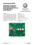
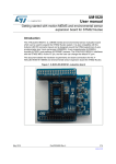
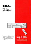
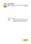
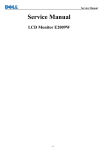
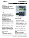
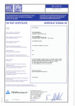
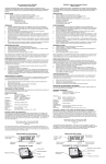
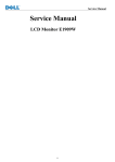
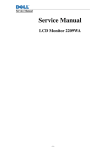
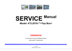
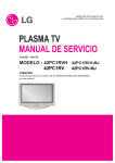
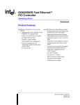
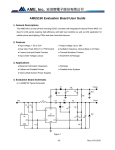
NCP1083WIRGEVB
LAYOUT AND SCHEMATIC
Figure 3. Layout Front
Figure 4. Layout Back
Figure 5. Silkscreen Front
Figure 6. Silkscreen Back
http://onsemi.com
3
NCP1083WIRGEVB
Figure 7. Schematic
http://onsemi.com
4
NCP1083WIRGEVB
Table 3. Bill of Materials
Substitution
Allowed
Pb
Free
Footprint
Manufacturer
Manufacturer
Part Number
TSSOPEP20
ON Semiconductor
NCP1083DEG
No
Yes
10%
0805-C-S
Walsin
0805B103K500CT
Yes
Yes
100 nF/100 V
10%
1206-C
AVX
12061C104KAT2A
Yes
Yes
Capacitor
SMD
100 pF/200 V
10%
0805-C-S
AVX
08052A101JAT2A
Yes
Yes
1
Capacitor
SMD
12 nF/50 V
10%
0805-C-S
AVX
08055C123KAT2A
Yes
Yes
Cfb2
1
Capacitor
SMD
1 nF/50 V
10%
0805-C-S
Walsin
0805B102K500CT
Yes
Yes
Cvddh
1
Capacitor
SMD
2.2 mF/16 V
(+80%)
to
(-20%)
0805-C-S
AVX
0805YC225MAT2A
Yes
Yes
Cgnd
1
Capacitor
SMD
2200 pF/2 kV
10%
1812
Walsin
1812B222K202LT
Yes
Yes
Cvddl
1
Capacitor
SMD
470 nF/50 V
10%
0805-C-S
AVX
08055C474KAZ2A
No
Yes
Csn2
1
Capacitor
SMD
470 pF/200 V
10%
0805-C-S
AVX
08052C47KJAT2A
Yes
Yes
Css
1
Capacitor
SMD
47 nF/50 V
10%
0805-C-S
AVX
08055C473KAT2A
Yes
Yes
Cft
1
Capacitor
SMD
47 pF/50 V
10%
0805-C-S
Walsin
0805N470J500LT
Yes
Yes
Cpd2, Cpd
2
Electrolytic
Capacitor
100 mF/63 V
(+20%)
to
(-20%)
CRD10.0L17.0R
M5.0
Hitano
EXR101M63
No
Yes
Cf
1
Capacitor
Polar
10 mF/20 V
10%
C-TANT-B
AVX
TAJB106K020R
Yes
Yes
Cout,
Cout1
2
Capacitor
Polar
33 m/25 V/
100 mR
10%
C-TANT-E
AVX
TPSD336K025R0100
No
Yes
T3
1
PoE Plus
Transformer
SM-00123
EFD20
NUFLUX
SM-00123
No
Yes
Daux2,
Dcs,
Dbw, Dgate
4
SMD
Switching
Diode
BAS16HT1G
SOD323
ON Semiconductor
BAS16HT1G
Yes
Yes
Daux1,
Dsec
2
Schottky
Rectifier
MBR20H100CTG
TO-220AB
ON Semiconductor
MBR20H100CTG
No
Yes
Dsn, Dsn1
2
SMD Ultrafast
Rectifiers
MURS120T3G
403A-03
ON Semiconductor
MURS120T3G
No
Yes
Dbr1, Dbr2,
Dbr3, Dbr4,
Dbr5, Dbr6
6
SMD Schottky
Rectifier
MBRS1100T3G
403A-03
ON Semiconductor
MBRS1100T3G
No
Yes
Zline
1
SMD TVS
Zener
1SMA58AT3G
SMA
ON Semiconductor/
Multicomp
1SMA58AT3G/
SMAJ58A
Yes
Yes
Ztvs
1
SMD TVS
Zener
1SMB100AT3G
403A-03
ON Semiconductor/
Multicomp
1SMB100AT3G/
SMAJ58A
Yes
Yes
Zaux1,
Zvaux
2
SMD Zener
MM3Z3V3ST1G
SOD323
ON Semiconductor
MM3Z3V3ST1G
Yes
Yes
Zbr3, Zbr4
2
SMD Zener
MMSZ16T1G
SOD123
ON Semiconductor
MMSZ16T1G
Yes
Yes
JOUT
1
Header, 6-Pin
Header 6
HDR1X6
FCI
8614-00-36-1-Y0-10
Yes
Yes
P1
1
Header,
10-Pin
Header 10
HDR1X10
FCI
8614-00-36-1-Y0-10
Yes
Yes
L1
1
Drum Core
Choke
10 mH/3 A
10X12
Prismatic
9404037403
No
Yes
Q1
1
MOSFET
N-Channel
FDP39N20
TO-220-AB
Fairchild
FDP39N20
No
Yes
Q4
1
MOSFET
N-Channel
FDS3992
SO-8
Fairchild
FDS3992
No
Yes
Qgate
1
Transistor
PNP
BFT92
SOT23
Philips
BFT92
Yes
Yes
Designator
Qty
Description
Value
U1
1
Power over
Ethernet
controller
NCP1083
Cbias1, Cf1
2
Capacitor
SMD
100 nF/50 V
Cline,
Cpd1
2
Capacitor
SMD
Csn1
1
Cfb1
Tolerance
http://onsemi.com
5
NC
NCP1083WIRGEVB
Substitution
Allowed
Pb
Free
Footprint
Manufacturer
Manufacturer
Part Number
PS2801-1-F3-A
SSOP4
CEL
PS2801-1
No
Yes
TL432BIDBZTG4
SOT23
Texas-Instruments
TL432BIDBZTG4
No
Yes
0805-R-S
Walsin
WR08X10R0FTL
Yes
Yes
0805-R-S
Walsin
WR08X1003FTL
Yes
Yes
1%
0805-R-S
Walsin
WR08X1002FTL
Yes
Yes
Designator
Qty
Description
Value
Tolerance
U2
1
High Isolation
Voltage SSOP
Photocoupler
U3
1
Programmable
Shunt Voltage
Reference
Rgate
1
Resistor SMD
10 W
Rfb4
1
Resistor SMD
100 kW
1%
Rvaux
1
Resistor SMD
10 kW
Rinrush
1
Resistor SMD
121 kW
1%
0805-R-S
Walsin
WR08X1213FTL
Yes
Yes
Rbr3, Rbr4
2
Resistor SMD
150 kW
1%
0805-R-S
Walsin
WR08X1503FTL
Yes
Yes
Rfb1
1
Resistor SMD
15 kW
1%
0805-R-S
Walsin
WR08X1502FTL
Yes
Yes
Rosc
1
Resistor SMD
182 kW
1%
0805-R-S
Walsin
WR08X1823FTL
Yes
Yes
Rbias2
1
Resistor SMD
1 MW
1%
0805-R-S
Walsin
WR08X1004FTL
Yes
Yes
Rterm
1
Resistor SMD
2.2 W
1%
0805-R-S
Walsin
WR08X2R2JTL
Yes
Yes
Rvaux1
1
Resistor SMD
2.21 kW
1%
0805-R-S
Walsin
WR08X2211FTL
Yes
Yes
Rdet1
1
Resistor SMD
24.9 kW
1%
0805-R-S
Walsin
WR08X2492FTL
Yes
Yes
Rs12
1
Resistor SMD
3.3 kW
1%
0805-R-S
Walsin
WR08X3301FTL
Yes
Yes
Rfb2
1
Resistor SMD
3.92 kW
1%
0805-R-S
Walsin
WR08X3921FTL
Yes
Yes
Rclass
1
Resistor SMD
30.1ĂW
1%
0805-R-S
Yageo
RC0805FR-0730R1L
Yes
Yes
NC
Rsn1
1
Resistor SMD
330E/1W
5%
2512-S
Walsin
WR25X331JTL
Yes
Yes
Rilim1
1
Resistor SMD
44.2 kW
1%
0805-R-S
Walsin
WR08X4422FTL
Yes
Yes
Rdet1
1
Resistor SMD
475 kW
1%
0805-R-S
Walsin
WR08X4753FTL
Yes
Yes
Raux1,
Rbias1, Rsl
3
Resistor SMD
5.1 kW
5%
0805-R-S
Walsin
WR08X512JTL
Yes
Yes
Rbw, Rsn2
2
Resistor SMD
75 W
1%
0805-R-S
Walsin
WR08X750JTL
Yes
Yes
Rfb3
1
Resistor SMD
8.25 kW
1%
0805-R-S
Walsin
WR08X8251FTL
Yes
Yes
Rdet2
1
Resistor SMD
845 W
1%
0805-R-S
Yageo
RC0805FR-07845RL
Yes
Yes
CST
1
SMT Current
Sensors-CST
Series
500 mH
SMD
Coilcraft
CST2-050LB
No
Yes
HS1
1
A10-220 Type
copper heat
sink
Custom,
see drawing
25 mm
X
14.5 mm
Yes
Yes
HS2
1
L Type Mosfet
copper heat
sink
Custom,
see drawing
25 mm
X
(38+20) mm
Yes
Yes
HS3
1
L Type Diode
copper heat
sink
Custom,
see drawing
25 mm
X
(38+20) mm
Yes
Yes
3
Screws
M3 X 10
Yes
Yes
6
Plain Washer
M3
Yes
Yes
3
Spring Washer
M3
Yes
Yes
3
Nut
M3
Yes
Yes
Cfb3
1
Capacitor
NC
0805-C-S
Yes
NC
Csi
1
Capacitor
NC
0805-C-S
Yes
NC
Zbr1, Zbr2
2
Diode Zener
16 V
MMSZ16T1G
SOD123
Yes
NC
Rcs
1
Resistor
0R4/3W
2512-S
Yes
NC
Rbr1, Rbr2
2
Resistor
150 kW
0805-R-S
Yes
NC
Rfb5
1
Resistor
NC
0805-R-S
Yes
NC
Q2, Q3
2
P-Channel
30 V (D-S)
MOSFET
Si7113DN
POWERPACK
1212-8
Yes
NC
NOTE: Only one set of components out of (Dbr5, Dbr6) and (Q2, Q3, Zbr1, Zbr2, Rbr1, Rbr2) is used.
http://onsemi.com
6
NCP1083WIRGEVB
ON Semiconductor and
are registered trademarks of Semiconductor Components Industries, LLC (SCILLC). SCILLC reserves the right to make changes without further notice
to any products herein. SCILLC makes no warranty, representation or guarantee regarding the suitability of its products for any particular purpose, nor does SCILLC assume any liability
arising out of the application or use of any product or circuit, and specifically disclaims any and all liability, including without limitation special, consequential or incidental damages.
“Typical” parameters which may be provided in SCILLC data sheets and/or specifications can and do vary in different applications and actual performance may vary over time. All
operating parameters, including “Typicals” must be validated for each customer application by customer’s technical experts. SCILLC does not convey any license under its patent rights
nor the rights of others. SCILLC products are not designed, intended, or authorized for use as components in systems intended for surgical implant into the body, or other applications
intended to support or sustain life, or for any other application in which the failure of the SCILLC product could create a situation where personal injury or death may occur. Should
Buyer purchase or use SCILLC products for any such unintended or unauthorized application, Buyer shall indemnify and hold SCILLC and its officers, employees, subsidiaries, affiliates,
and distributors harmless against all claims, costs, damages, and expenses, and reasonable attorney fees arising out of, directly or indirectly, any claim of personal injury or death
associated with such unintended or unauthorized use, even if such claim alleges that SCILLC was negligent regarding the design or manufacture of the part. SCILLC is an Equal
Opportunity/Affirmative Action Employer. This literature is subject to all applicable copyright laws and is not for resale in any manner.
PUBLICATION ORDERING INFORMATION
LITERATURE FULFILLMENT:
Literature Distribution Center for ON Semiconductor
P.O. Box 5163, Denver, Colorado 80217 USA
Phone: 303−675−2175 or 800−344−3860 Toll Free USA/Canada
Fax: 303−675−2176 or 800−344−3867 Toll Free USA/Canada
Email: [email protected]
N. American Technical Support: 800−282−9855 Toll Free
USA/Canada
Europe, Middle East and Africa Technical Support:
Phone: 421 33 790 2910
Japan Customer Focus Center
Phone: 81−3−5817−1050
http://onsemi.com
7
ON Semiconductor Website: www.onsemi.com
Order Literature: http://www.onsemi.com/orderlit
For additional information, please contact your local
Sales Representative
EVBUM2029/D