1
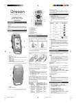
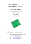
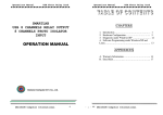
HANDHELD SCIENFITIC, INC. HTML5 Enabled Wireless Embedded Module User Guide V1.0 2 Copyright © 2012 Handheld Scientific, Inc. [email protected] All Rights Reserved 3 4 Table of Contents Chapter 1 Quick Start .................................................................................................... 7 Chapter 2 Hardware Description ................................................................................... 9 2.1 Embedded Module ............................................................................................... 9 2.2 Development Board............................................................................................ 12 Chapter 3 Flash File System ........................................................................................ 17 Chapter 4 WiFi Modes and Configuration .................................................................. 19 Chapter 5 Data Acquisition and Control Commands .................................................. 23 List of Commands ......................................................................................................... 26 Chapter 6 Client Development .................................................................................... 29 6 Chapter 1 Quick Start This Guide provides minimum amount of information needed to test the module and development board. 1. When the development board was shipped, the battery jumpers were in OFF position to prevent the board from accidentally turning on. Move the two jumpers to connect the battery, as shown in the following pictures. Battery jumpers in OFF position Move jumpers to ON position 2. Press the red RESET button. The green LED on the module should start flashing. If not, the battery may be completely discharged. In such case connect the wall charger to the module via USB cable before pressing the RESET button. Note 1: In spite of the label, the ON/OFF button can only turn the module OFF. To turn it on, the RESET button has to be used. Note 2: The mini USB connector on the module is for both communication and battery charging. In normal circumstances, the barrel power jack connector on the development board does not need to be used. 3. Wait for the green LED to become flashing slowly (once every 2 seconds). This indicates the WiFi network has been established. By default, the module enters Limited AP (Access Point) mode. It creates its own WLAN (Wireless Local Area Network) like an access point. Press the MODE button quickly, the module will announce its configuration (Mode, IP address, etc.) via the speaker. The default WLAN name is DCA_xxxx where xxxx is the last 4 digits of the module’s MAC address. The IP address is 169.250.1.1. For detailed information on WiFi, refer to Chapter 4 of this document. 4. On a client device (iPhone/iPad, Android, PC or MAC), connect to the WiFi network created by the module. The module has a DHCP server so make sure the client has DHCP enabled such that its IP address is assigned by the module. For the first time, it may take a while for the IP address assignment to take place and connection to establish. Subsequent connections will be faster. 5. Once connected, in a supported browser, type in http://169.250.1.1. The user interface should show up. As of 08/2012, current versions of Chrome, Firefox and Safari are supported. For Opera, WebSocket is disabled by default. It needs to be turned on before the program can work. IE 9 does not support WebSocket while its next version, IE10 (in Beta), does. Apple devices should all work using the current Safari browser. For Android devices, the default browser does not work. You will need to download Firefox, Opera or Chrome (in Beta) 6. In the web user interface, click Connect and you should see connected in the console. Now try to turn on/off the LEDs, change the brightness of the green LED on the board. Click the Enable button next to Analog Inputs and you will see 4 channels of analog data rolling in. Now change the potentiometers, touch the temperature sensor or shed light on the light sensor to see the displayed values change. For detailed information on client application development, refer to Chapter 6 of this document. 7. Using the USB cable (mini-B plug to standard-A plug), connect the module to an USB port on a PC or MAC. The module will show up as an USB flash drive. A current version of the User Manual is in the /doc directory. You should copy it over to a PC for viewing. For detailed information regarding flash file system, refer to Chapter 5 of this document. It is strongly suggested not to turn on the module while connected to a PC via USB. Instead, you should disconnect the cable, turn on the module, wait for a few seconds to let the initialization process complete and then connect USB. Keep in mind this is an embedded module running on a small microcontroller with very limited resources. Multiple tasks running at the same time may interfere with each other, especially for those like USB operations that require strict timing. Note: For Firmware v1.0, only one client can be connected at a time. Future firmware will support multiple client connections simultaneously. 8 Chapter 2 Hardware Description This chapter describes the hardware of the module and development board. 2.1 Embedded Module The layout of the module is shown in the following picture. 1. Audio Amplifier Gain Adjustment: there is an audio amplifier on the module and its volume is adjustable. The output of the amplifier is through Pin 2 (Vout1) and Pin 3 (Vout2). The input of the amplifier is DAC1. By default, this DAC1 channel is used by the module to output audio announcements. The announcement feature can be turned off by a command so DAC1 is free for use for other purpose. 2. Connector Pin 1: make sure to align this pin to pin 1 of the socket on development board when insert the module to the board. 3. WiFi Transceiver connection: connection between the on-board microcontroller and the WiFi transceiver. In normal use, the connection is closed by jumpers. However, user can remove the jumpers and connect cables to communicate with the WiFi transceiver directly. For example, this can upgrade the firmware of the transceiver. 4. Power OFF Button: pressing this button will turn off the module. It is worth noting that even when the module is powered off, part of the circuit including the MCU is still energized. The MCU is in deep sleep mode. The current consumption is around 25uA when the module is powered off. For version 1 of the board, the marking for the button (ON/OFF) is a little misled. This button only turns the module off. It does not turn it on. Use the reset button to turn it on. 5. RESET Button: pressing this button will turn on the module if it is off, or restart the module if it is already running. 6. WiFi Antenna Connector: standard U.FL connector for connecting a WiFi antenna. The WiFi transceiver requires an external antenna to maximize performance. 7. Connector Pin 21: when plug the module into the development board, make sure this pin aligns with the same pin of the socket. 8. WiFi Transceiver: low-power high performance WiFi transceiver that is compatible with b/g/n WiFi standard. 9. System Status LED (Green): there are 3 flashing speeds indicating different system status: Very fast (10 times per second): module in boot loader mode. Usually the module stays in this mode only briefly. If the boot loader can’t find a valid application firmware, it will stay in this mode indefinitely. It will also stay in this mode for longer time if a new firmware is found and written to the module. Fast (4 times per second): module is booting up. Setting up WiFi, etc. Slow (once every 2 seconds): module is ready. It has obtained a valid IP address and ready to be connected. 10. Power Status LED (Red): if USB power is present, this LED will stay on. If USB power is not present, when battery voltage falls below 3.7V, this LED will start flashing slowly (once every 2 seconds) and it will flash faster and faster as battery voltage dropping. 10 11. Mini USB Connector: for power supply and communication. When plugged in a PC, the module will show up as a USB flash drive. See Chapter 3 Flash file System for more details. Module pin assignment Pin 1 2 3 4 5 6 7 8 9 10 11 12 13 14 15 16 17 18 19 20 Label GND Vout1 Vout2 DAC1 DAC2 P6 P7 P8 P9 P10 P11 P12 P13 P14 P15 P16 P17 P18 RESET GND Pin 21 22 23 24 25 26 27 28 29 30 31 32 33 Label GND Vbak P23 P24 P25 P26 P27 P28 P29 P30 P31 P32 RSVD Description Ground Audio Amplifier Output 1 Audio Amplifier Output 2 Digital-Analog Converter Channel 1 Digital-Analog Converter Channel 2 DIO1 (Digital I/O Channel 1) DIO2 (Digital I/O Channel 2) ADC1 (Analog-Digital Converter Channel 1) ADC2 (Analog-Digital Converter Channel 2) DIO3 (WiFi mode announcement/switching button) DIO4 (user button) ADC3 (Analog-Digital Converter Channel 3) ADC4 (Analog-Digital Converter Channel 4) ADC5 (Analog-Digital Converter Channel 5) ADC6 (Analog-Digital Converter Channel 6) ADC7 (Analog-Digital Converter Channel 7) ADC8 (Analog-Digital Converter Channel 8) Power Off. A low voltage pulse turns module off Reset. A low voltage pulse resets the module Ground Description Ground Battery connector for backup registers DIO5 (Digital I/O Channel 5) DIO6 (Digital I/O Channel 6) DIO7 (Digital I/O Channel 7) DIO8 (Digital I/O Channel 8) DIO9 (Digital I/O Channel 9) DIO10 (Digital I/O Channel 10) DIO11 (Digital I/O Channel 11) DIO12 (Digital I/O Channel 12) DIO13 (Digital I/O Channel 13) DIO14 (Digital I/O Channel 14) Reserved. Should not be used. 11 Channel a b c d e f g h i j k l m n o Channel p q r s t u v w x y 34 35 RSVD VMCU 36 VCC 37 BAT 38 39 40 BAT Vin Vin Reserved. Should not be used. 3.3V MCU voltage. Present even when module is turned off. 3.3V Voltage. Not present when module is turned off. External Li-ion battery connector. If Vin is present, it will charge the battery Connected to Pin 37 5.0V input voltage. 300mA. (See Note 1) Connected to Pin 39 Table 2-1 Module Pinout Note 1: Vin (Pins 39/40) is connected to the VCC/5V pin of the USB connector. Never supply this pin with 5V voltage AND plug in the USB cable at the same time. The DAC and ADC channels are all 12-bits and use 3.3V as reference voltage. The outputs of the module have already been converted to the actual values with 3 digits after decimal point (e.g., 1.234) 2.2 Development Board The development board is used to test and demo the module. The following picture illustrates its layout. 12 Figure 2-2 Development Board Layout 1. Antenna Connector: connect a duck antenna for maximal WiFi performance. 2. Battery: 1200mAH 3.7V 4.4Wh Li-ion battery. 3. Potentiometer (ADC1): 10K pot for input to analog-digital converter channel 1. 4. Speaker: speaker for audio output. 5. Power Selection: the development board has its own power supply for extra circuit. The board can use the module’s power or its own power. This is selected by jumpers J5A and J5B. Both J5A and J5B jumpers should be moved at the same time. When J5A/B are in the MOD side, the development board is powered by the module. When J5A/B are in the EXT side, the development board is powered by the power supplied from Power Socket (6). 6. Power Socket: external power supply (5-9V DC, 500mA, Inner Positive) for the board. Normally the board is powered by the module so this connector is not used. 7. 3.3V Power Connector: power supply for extra circuit. This voltage is present when an external power supply is plugged in the power socket (6). 13 8. Potentiometer (ADC2): 10K pot for input to analog-digital converter channel 2. 9. LED2 (DAC2): LED for analog output from digital-analog converter channel 2. 10. Temperature Sensor (ADC3): input for analog-digital converter channel 3 11. Light Sensor (ADC4): input for analog-digital converter channel 4 12. Mode Button: if held for less than one second, the module will announce its current configuration (WiFi mode, IP address, etc.) If held for more than one second, the module will attempt to switch to the next configured WiFi mode. See Chapter 4 for details regarding WiFi modes. 13. User Button: user defined button connected to DIO2 14. Reset Button: a low pulse resets the module. This is connected in parallel with the Reset button on the module. 15. Power OFF Button: a low pulse turns off the module. This is connected in parallel with the OFF button on the module. For version 1 of the board, the label of the button (ON/OFF) is a little misled. This button does not turn on the module. It only turns it off. Use the reset button to turn it on. 16. LED Array: 10 LEDs connected to 10 Digital IO channels. Note a LED will turn on when the output is low (zero) instead of high (one). This is because current sourcing capability of a MCU pin is better than current driving capability so low voltage is used to turn on the LED. 17. Connector Jumpers: the jumpers are used to connect inputs/outputs of the module to the development board. For instance, a jumper connects P08 pin on the module to the potentiometer output ADC1 on the development board. When the jumpers are removed, cables can be used to reshuffle the connections, or to connect to external sensors/circuits. 18. Module Sockets: 2x20 sockets for the module. 19. Connector Jumpers: same as (17). 20. Battery Jumpers: two jumpers connecting the on-board battery to the module. When the board is shipped, the jumpers are disconnected to prevent the battery from discharging. User should move the jumpers to connect the battery before using the product. 14 Audio announcements: when the module starts up, it will announce the firmware version. When the mode button is pressed, it will announce network settings. Note that audio announcements are resource-intensive operations. It may interfere with or be interfered by other operations. For instance, when the module is connected to a PC via USB, the voice announcement may slow down or even appear to be shattered. Audio announcements may also pause data input/output operations. Therefore, this feature should be used judiciously. As shown in the next picture, the development kit includes a module, a development board, USB wall power adapter with cable, duck antenna and battery. 15 Chapter 3 Flash File System The Mini USB port on the module is served for both power supply and communication. When plugged into a PC or MAC, the module shows as up as an USB flash drive. The size of the drive is 8MB. The file system is standard FAT so file names are case insensitive. It only supports 8.3 filenames (8-character name plus 3-character name extension). It is strongly recommended to eject the drive before unplugging the USB cable. This will maintain data integrity by making sure all data are written to the drive before the cable is disconnected. The first time the module is used, you should make a backup of all files to a PC or an external drive. In normal use of the module, the USB flash drive should be disconnected from the PC. This is especially important if the module is used for intensive data acquisition tasks. Using the USB drive with intensive DAQ tasks may disrupt the timing of both USB and DAQ operations. The following picture shows the directory structure: DOC: contains documentation of the module. The files here can be deleted to free up space after being backed up to a PC. FIRMWARE: if a new firmware is available, download and put it in this directory. Each time the module starts up, it looks into this directory for firmware. If it finds one with version higher than the one in program flash memory, it will replace the current firmware with the new one. After the firmware is upgraded, user should delete the file in this directory to free up space and speed up initialization process. SYSTEM: contain essential files for the proper operation of the module. For instance, the WiFi configuration file lives here. Users should add or delete files in this directory with great caution. WEB (optional): Users can put web files (HTML, JavaScript or images) in this directory. Alternatively, those files can also be put in the root directory just for simplicity. The web server in the module uses the root directory as document root. Therefore, if a file is in the web directory, the resource path in the URL needs to include the directory path as well. The speed to copy files to the flash drive is ~30KB/s. The speed to load files from the web server via WiFi is ~50KB/s. As an example, for a 2MB file, it takes about 70 seconds to write, and about 40 seconds to load on a web browser. The web server does not support If-Modified-Since header so it will send out the files as requested every time. It is recommended to put large web files in a separate external web server and link the files if necessary. The total size of required system files is no more than 1MB. This leaves at least 7MB space for user contents. 18 Chapter 4 WiFi Modes and Configuration WiFi in the module can be configured for one of three modes: Ad-Hoc, Infra-structure and Limited Access Point (AP). Ad-hoc and Infra-structure modes are standards in WiFi technology. Ad-Hoc mode is point-to-point communication between two devices without an access point. Intrastructure mode is used to connect to an access point which routes data traffic among devices. Since Ad-Hoc mode has no security, some devices do not support Ad-Hoc Mode, such as Android phones and tablets. Therefore, a third mode, Limited AP mode, was developed to address that issue. In Limited AP mode, the module creates a WiFi network like an AP so that devices can talk to each other without an access point. However, it does not have all the capabilities of an AP (thus the name limited AP). All three modes can be configured using a configuration file in the module’s file system. The file is config.txt in the SYSTEM directory (/SYSTEM/config.txt). User can also switch among modes with the mode switch button or by controlling the mode switching pin. When the mode button is pressed and held for less than one second, network configuration is spoken. If pressed for more than one second, the module attempts to switch to the next mode in the configuration file. In infra-structure and AP modes, standard WLAN securities are supported: WEP, WPA and WPA2. When starting up, if the configuration file does not exist, the module will enter the default limited AP mode with the following parameter: SSID: DAC_xxxx where xxxx is the last 4 digit of the MAC address. IP address: 169.250.1.1 Net Mask: 255.255.0.0 Gateway: 169.250.1.1 Security: none (open) When the module was shipped, a configuration file was placed in the /SYSTEM director in the flash file system. It content is listed below. For demonstration purpose, this file contains redundant information. For instance, the network security is set to open (no encryption) so the wpa_passphrase setting is not needed but it is present anyway. In the configuration file, directives are listed line by line. A line starting with a “#” or “//” is comment and ignored. Below are the directives that can be placed in the configuration file. Not all directives are applicable to all modes. [Limited AP], [Infra Structure], [Ad Hoc] Section headers. Each header indicates the start of a section. Directives after a section are for the specified mode. wlan_ssid The SSID of the WLAN. If the string ends with an underscore, the last 4 digits of the MAC address are appended to the SSID. This is useful to create a unique SSID. In Ad Hoc or Limited AP mode, the module creates its own WLAN with the specified SSID. In infra-structure mode, this is the SSID of the WLAN to join. ip_address In Ad-Hoc or Limited AP mode, this is the IP address of the module. In Infrastructure mode, if DHCP client is enabled, this setting is ignored and the IP address is assigned by the DHCP server. 20 net_mask Network Mask. In Infra-structure mode, if DHCP client is enabled, this will be ignored and the net mask will be assigned by the DHCP server. gateway Default gateway. In Infra-structure mode, if DHCP client is enabled, this will be ignored and the gateway will be assigned by the DHCP server. http_port The port at which the web server and WebSocket server are listening to. dhcp_server Takes true/false value. Whether to turn on DHCP server in the module. This is only applicable in the Limited AP mode. dhcp_client Takes true/false value. Whether to turn on DHCP client in the module. This is only applicable for infra-structure mode. If this is true, the IP address, net mask and gateway are all taken from the DHCP server. Those directives, if present, are ignored. security WLAN security. Not applicable in Ad-Hoc mode. In the other two modes, it can be one of the following values: auto: automatic selection. Should be used in infra-structure mode where security setting is determined by the Access Point. open: no security. Network is open. wep: WEP security. If this is specified, wep_key1 (and wep_key2 if so desired) need to be specified. wpa-psk: WPA Pre-shared key security. If this is specified, wpa_passphrase also needs to be specified. wpa2-psk: WPA2 Pre-shared key security. If this is specified, wpa_passphrase also needs to be specified. 21 wpa_passphrase If security is set to wpa/wap2, this value specifies the WLAN passphrase. It should be a string containing 8-63 ASCII characters. It is used as a seed to create the WPA pre-shared key. wep_mode Applicable only when security is set to wep. This specifies the wep mode. It takes one of the following three values: none, open or shared. wep_key1 WEP security key 1. It is either 10 or 26 hexadecimal digits corresponding to a 40-bit or 104-bit key. wep_key2 WEP security key 2. It is either 10 or 26 hexadecimal digits corresponding to a 40-bit or 104-bit key. default Takes true/false value. Specifies whether this mode is the default when the module starts up. There should be only one mode with default set to true. If no default is set to true, the Limited AP mode is the default. If more than one default is set to true, the last one prevails. 22 Chapter 5 Data Acquisition and Control Commands After connected to the module, a client (web browser) can send commands to the module to perform control and data acquisition tasks. The main design goal for the commands and responses is efficiency. A command contains one or more space separated words and is terminated by line feed (0x0A), or carrier return (0x0D) or both. Some commands generate response and some don’t. For those commands that do not generate response, there is no indication whether they were successfully taken. The client needs to query the relevant value to make sure the command succeeded. For example, command “set period 1000” will be silently accepted. Client should issue another query “get period” which returns “F1000” to make sure the value was set correctly. Responses from the device are separated by space. Each response is in the form of <channel><value>. For instance, e1.23, h0, h1, E01111101101101. The purpose of including a channel designation in each response is to make the responses autonomous so they are independent of the sequence of the commands that were sent. There are two types of channels: regular and special. A regular channel corresponds to a physical input/output such as a DAC, ADC or DIO. A special channel does not correspond to a real channel. Instead, it is used to indicate a pre-defined value or values such as a version, or aggregation of multiple DIO values. Channels are designated by a single letter for parsing efficiently in the client. Regular channels are designated by lower case letter. For instance, there are 2 DAC channels designated as a and b, 8 ADC channels designated as e, f, and so on. The following table shows all regular channel designations. Pin 4 5 6 7 8 9 10 11 12 Label DAC1 DAC2 P6 P7 P8 P9 P10 P11 P12 Description Channel Digital-Analog Converter Channel 1 Digital-Analog Converter Channel 2 DIO1 DIO2 ADC1 (Analog-Digital Converter Channel 1) ADC2 (Analog-Digital Converter Channel 2) DIO3 (key) DIO4 (user button) ADC3 (Analog-Digital Converter Channel 3) a b c d e f g h i Interrupt Capable Yes - 13 14 15 16 17 18 23 24 25 26 27 28 29 30 31 32 P13 P14 P15 P16 P17 P18 P23 P24 P25 P26 P27 P28 P29 P30 P31 P32 ADC4 (Analog-Digital Converter Channel 4) ADC5 (Analog-Digital Converter Channel 5) ADC6 (Analog-Digital Converter Channel 6) ADC7 (Analog-Digital Converter Channel 7) ADC8 (Analog-Digital Converter Channel 8) Power OFF Switch DIO5 DIO6 DIO7 DIO8 DIO9 DIO10 DIO11 DIO12 DIO13 DIO14 j k l m n o p q r s t u v w x y Yes Yes Yes Yes Yes Yes Yes Yes Yes Special channels are designated by uppercase letters, as defined in the following table. Description Battery Voltage USB Power Status Firmware Version Hardware Version DIO Channel Aggregation Transmission Period Value Sampling Group Value Audio ON/OFF status Channel Setting Channel A B C D E F G H I Sample Response Values A3.85 B0 C1.0 D1 E11011011011011 F1000 G1 H1 Ih01 The E channel is for controlling all DIO channels in one command. There should be 14 0/1’s following the command, corresponding to 14 DIO channels: cdghpqrstuvwxy. This command will only affect the channels set to output. As an example, the g channel (P10, DIO3) is by default set to input for the MODE switching operation so it is not affected by the command, unless this channel is re-defined as output by the user. There are three ways to get data from the module: repeatedly query (client pull), automatic sampling (device push) and interrupt. In the first method, a client simply sends the read command (the r command) repeatedly. In this case the client has complete control over when and what channel to pull the data. The main drawback of client pulling is efficiency. For each request and response, a data packet is created and transmitted which may contain high overhead for packet header and so on. Therefore, client pull is limited to 10 times per second. 24 The second method is automatic sampling, or device push. Each channel has an on/off property which can be toggled by a command. When automatic sampling starts, the data from all channels that are “on” will be sent out continuously, without the need for intervention from the client. There are two parameters associated with automatic sampling: period and group. The period value is the interval between consecutive transmissions of data from the device. The group value is the number of samples (for each channel) in one transmission. For instance, if period=500 and group =10, then samples are transmitted once every 500ms and in each transmission, there are 10 samples taken at equally spaced interval during that 500ms. This is effectively the same as period=100 and group=2. However, the former is more efficient since it transmits 10 samples all at once, while the latter transmits only 2 samples at a time. Efficiency is important when the data transmission rate is high, and it is the main purpose of having the period and group parameters separately. The unit of the period parameter is ms (milli second). It can range from 100 to 60000 (100ms to one minute). In other words, the transmission rate can be from 100 transmissions/second to once per minute. The group parameter can range from 1 to 100. If period=100 and group=100, the effective sampling rate is 1KHz which is the highest the module can achieve. There is one more scenario. For a DIO channel, when an input level changes such as from 0 to 1 or from 1 to 0, the client would like to be informed of the changes immediately. Neither client pull or device push is appropriate or efficient in this situation. In this case we would like the device to send out an unsolicited message upon the occurrence of the event. This is called interrupt event. For each DIO channel, interrupt can be enabled or disabled. If enabled, which is the default setting, when the input level changes, the device will send out a data message, as if the channel was queried by the client. For instance, when the user button is pressed or released, a message of h0 or h1 is sent to the client. With the sample web interface, this causes the LED display on the web page to change color, illustrating the real-time interrupt capability of the module. Due to some hardware limitations, not all DIO channels are capable of interrupt. Please refer to the above table for the information. All those 3 data acquisition methods can be used at the same time. For example, user can set up a device push for an ADC channel with fast changing value, and pull a slow changing value (such as battery voltage) at much longer interval while interrupts inform the application any digital level shift. The total aggregated throughput of the module is around 50kbps (bits per second), limited by the processing capability of the MCU. Each analog data needs 7 bytes (one byte of channel designation, 5 bytes of data including a decimal point, one white space separator). Each DIO channel needs 3 bytes. So if the sampling rate is at its maximum of 1K, only 25 one analog channel can be enabled, or 3 DIO channels can be enabled. Users can use those data to estimate the maximal sampling rate for desired channels. List of Commands r [channel] The read command. If there is no parameter, the command returns data of all channels whose automatic sampling setting is on. If an optional channel parameter is present, the command returns data of that particular channel. w <channel><data> The write command. Write the data to the specific channel. Note there is no space between <channel> and <data>. For example, “w b2.34” channel <channel> on|off Turn the channel on/off for automatic sampling. For example, “channel f on” channel <channel> [in|ipd|ipu|out_od|out_pp] Set a DIO channel to the specific mode. Note this is not applicable to analog (ADC or DAC) channels. in: floating input (no pull-up or pull down). ipd: digital input with pull-down ipu: digital input with pull-up out_od: output, open drain out_pp: output, pull-push “channel h ipd” sets the channel DIO1 to floating input. “channel s out_od” sets the channel DIO8 to open drain output. Examples: channel <channel> irq_on|irq_off Turn interrupt on/off. Only applicable to DIO channels. If interrupt is on, when there is a change in the digital level of the input, the module will send out an unsolicited output to the client. The default is on for all DIO channels. Note: due to hardware limitation, not all DIO channels are interrupt capable. set period <value> 26 Set transmission period (interval) for automatic sampling. Unit is in ms (1000th of a second). Value should be between 100 to 6000 (once every 100ms to once every minute). set group <value> Set the number of samples in each transmission for automatic sampling. Default value is 1. The range is 1-100 inclusive. set audio on|off Turn the audio output on and off. If audio is turned off, DAC1 channel can be used for other purpose. The default is on. get period Get transmission period for automatic sampling. Returns “Fn” where F is the special channel designation and n is the value. For instance, “F100” or “F500”. get group Get the group setting value. Returns “Gn” where G is the special channel designation and n is the value. For instance, “G1” or “G10”. get audio Returns the audio output on/off status. Returns “H0” or “H1” where H is the special channel designation. start Start automatic sampling (device push) based on transmission period and sampling group values. stop Stop automatic sampling. 27 28 Chapter 6 Client Development Clients are written in HTML/JavaScript running in browsers that support HTML5. The only required HTML5 feature is WebSocket, although Canvas is used for the demo web page. Other HTML5 features such as Local Storage and Web Workers are helpful in developing feature-rich applications but not required to use this product. The module and demo code have been tested to work in the following browsers: Chrome from 19.0, FireFox from 12.0, Safari from 5.1, Safari on iOS from 4.2, IE 10.0 and Opera 12.0. Note that as of this writing, the current IE version is 9.0 which does not support WebSocket. The next version, IE10, available on Windows 8, does support WebSocket. WebSocket support is enabled by default in all supported browsers except Opera. In Opera, a user needs to turn the feature on manually: in its address input, type in opera:config. On the page displayed, expand User Prefs and select the checkbox Enable WebSockets. Then scroll down all the way and click Save. Now the code should work in that browser. The HTML5 WebSocket API is relatively simple. The full spec can be found here: http://dev.w3.org/html5/websockets/. The following are essential steps for a minimal working program: ws = new WebSocket(url) Open a new WebSocket to url which must be in the form of ws://host:port/resource ws.onopen(evt) WebSocket open event handler. It is called when a connection is open successfully. ws.onmessage(evt) Data arrival event. Parse and process data here. Since the function will be called repeatedly, try best to re-use memory and leave as little garbage as possible. ws.onclose(evt) Socket closed. Clean up resources. ws.onerror(evt) Error handling. We provide sample programs to illustrate how to use the API and develop applications. The following screen shot shows the demo program coming with the module. This is the /index.htm file in the module’s flash file system. 30 31 Click Connect to open a WebSocket connection to the URL specified in the Server text box. The host (IP address) is where the file is loaded from (the module’s IP address). User can change the address to connect to a different WebSocket server. This is useful for developing/testing new applications since you don’t need to copy the files to the module every time a change is made. If a connection is successfully established, the console will show “Connected”. Otherwise error message will be shown. Once a connection is opened, commands can be typed in the Command text box. For instance, typing in “r h” then hitting Send (or pressing Return) will read the DIO channel connected to the user button. The command “r” will return the data for all channels whose automatic sampling setting is on. Clicking on the LEDs will turn on/off the corresponding LEDs on the board. Moving the Analog Output slider will change the brightness of LED2 on the board. If you click “Repeat Send”, the software will send the command specified in the Command input box with the interval specified in the Interval box. This is client pull explained in the previous chapter. To experience with device push, execute the command start and see data rolling in on the console. The stop command will stop automatic data push. For analog input, clicking the Enable button will turn on all those 4 analog channels (you can see the commands sent in the console). After that, you can use client pull or device push to get data from the module. We hope you found the information in this manual useful. If you have any comments or questions regarding this document, or any of our products, please feel free to contact us at [email protected]. We love to hear from you! 32