1
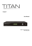
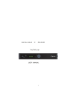
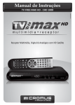
INTRODUCTION
This User Manual will help you to operate your receiver in a safe manner while enjoying
all the features and benefits it provides for your entertainment
This User Manual must be read by every person that is:
•
Installing
•
Connecting
•
Operating
•
Cleaning
DISPOSAL OF USED ELECTRICAL AND ELECTRONIC DEVICES
All products that are marked either directly or labeled on the packaging with the following
icon:
cannot be disposed of through the normal household waste channels. These products
must be disposed of through specialised collection centres for the recycling of electric
and electronic devices
By disposing of this product as required by law, you are contributing to the protection of
the environment.
Incorrect disposal can be dangerous to human health and hazardous to the environment.
2
Table of contents
Safety Instructions
4
Positioning
5
Front Panel / Rear Panel
7
Remote Control Unit
9
Connecting your STB
11
Main Menu
13
1. Channel Manager
13
2. Installation
14
3. Settlings
15
4. Timer
17
5. STB Update
17
Trouble Shooting
19
Specification
20
Safety precautions
Before operating the receiver, please thoroughly read the following safety precautions.
You are required to read all the notes, instructions and warnings contained in this User
Manual
3
Basic safety precautions
Connecting to the mains
· During electrical storms unplug the receiver from the mains.
· To avoid the risk of fire and electric shock, do not expose the receiver to any water.
Keep away from exposure to the sun.
· Don’t open the housing otherwise there is the risk of electric shock.
· Only connect the receiver to a properly installed 100-240V, 50-60 Hz mains socket.
· When appliance is not used for long periods of time, please disconnect the plug from
the mains.
· If objects or liquids enter the receiver, immediately unplug power from mains. Refer
appliance to a qualified service technician before using it again otherwise there is a risk
of electric shock.
· Please make sure that the power supply (socket) is easily accessible.
· Do not damage the mains cable.
· If the mains cable is damaged, refer to a qualified DGTEC technician for repair before
using the receiver again otherwise there is the risk of electric shock.
· Do not allow children to use the receiver without supervision.
· Always refer maintenance to a qualified DGTEC technician. Purchase spare parts from
the manufacturer only.
4
Positioning
Place the receiver on a stable, even surface.
Avoid placing it near:
¾ Sources of heat
¾ Naked flames, like candles,
¾ Devices with strong electromagnetic fields, like speakers.
¾ Do not place objects filled with liquids (such as vases) on the receiver.
· Avoid direct sunlight and exceptionally dusty places.
· Never cover the ventilation holes. Ensure sufficient ventilation of the receiver.
· Do not place heavy objects on the receiver.
· Humidity can occur inside when moving the receiver from a cold to a warm place. In this
case, wait for about 1 hour before operating the unit.
Run the antenna cable so that no one can step on or stumble across it.
.
5
General Introduction
UNPACKING
Unpack the unit and check to make sure that all of the following items are included in the
packing:
1X Remote Control Unit (RCU)
1X User’s Manual
2X AAA batteries
1X Digital Terrestrial Receiver
1X Composite cable
1X Component Cable
6
Front Panel/ Rear Panel
Front Panel
(1)
STANDBY: Switches the STB between operation and standby modes.
(2)
CH (-/+):
(3)
VOL (-/+): Turns up/down volume or changes the page of channel list.
(4)
OK:
Display the channel list and selects the item on the menu.
(5)
MENU:
To display the main menu or return to a previous menu.
(6)
DISPLAY: Display the channel number while operating and the
Change channel or items from top to bottom on the menu.
.
time while in standby mode.
7
Front Panel/ Rear Panel
Rear Panel
(1)
(2)
(3)
(4)
(5)
(6)
(7)
(8)
(9)
(10)
AERIAL IN: Input for antenna.
LOOP OUT: Loop signal output to VCR, etc.
ETHERNET:To connect network (to be used when specified)
HDMI connection
S/PDIF: S/PDIF audio format output system.
S-VIDEO: S-VHS Video output
Y/Pb/Pr RCA A/V: Component connection (Y/Pb/Pr)
POWER: Power ON/OFF switch
A/V RCA: To connect the Audio/Video RCA output to TV.
RS-232: To connect to your PC for software upgrade (only used by qualified
DGTEC technician)
8
Remote Control Unit
9
Remote Control Unit
1
2
3
4
STANDBY
MUTE
NUMBERIC
BUTTONS
FORMAT
Switch between Operation and Standby mode
Turn off volume
Changes channels or selects the menu
options.
Press to select the video output mode of 1080I,
720P and 576P. When change a video format,
there will be flicker for second when change
format.
5
MENU
6
OK
7
CH (▲/▼)
8
9
10
11
12
13
14
15
AUDIO
PAUSE
TXT
SUBTL
USB
TV/RADIO
BACK
PAGE UP/DOWN
Turn to the main menu or return to previous
menu
Enter into the menu you choose or select the
current option
Change channels or items from top to bottom
on the menu
Change audio mode to left right and stereo
Pause to freeze the screen while watching TV
View the Teletext information
To display the Subtitle text
To display the USB list
Switch between TV and Radio mode
Returns to previous command
Press to jump one page up; or change EPG
program list up or down.
16
17
EXIT
VOL (◄/►)
18
19
20
A.RATIO
FAV
INFO
21
GUIDE
Return to previous menu
Turn up/down volume; Change the page of
channel list.
16:9/4:3
Enter into favorite list
Display information of programs and current
settings
Opens program guide application
Installing the batteries in the remote control
1. Press down on the retaining catch on the lid of the battery recess on the remote
control and remove the lid.
2.
Insert two AAA batteries into the recess.
Be careful to insert the batteries as shown in the diagram inside the recess.
3. Replace the lid over the recess and gently push down on the lid until it snaps firmly
into place.
10
Connecting your STB
Step 1: Connect to the antenna
Connect the antenna lead coming from the wall plate to the AERIAL IN socket.
Step 2: Choose your Connection
There are a number of methods for connecting your STB to the television, depending on
your preference and the connection types on your TV. These methods are labeled A, B
and C below.
A: Y / Pb / Pr (Component) using the supplied RCA blue–red–green lead
For Component video, connect with the supplied Y / Pb / Pr Component cable (green,
blue and red leads). Connect the leads to the Y, Pb and Pr sockets on the back of the unit,
and then to the corresponding Component sockets on your TV. Please pay attention to
the color-coding. You will also need to establish a connection for left and right audio via
the audio sockets. This can be done using the supplied RCA cable.
For right audio, connect the red RCA lead and for left audio, connect the white RCA lead.
B. HDMI connection
If your TV has a HDMI input, you can use a HDMI cable from the back of STB to the rear
of the television. A HDMI lead supplies both audio and visual through the single cable so
no audio leads are necessary.
Please ensure that your television is set to the HDMI input mode for detection of STB
device to be made.
C: CVBS (Composite) using the supplied RCA red–white–yellow lead (basic TV’s)
Using the appropriate color-coding, you can connect to your TV with the supplied RCA
cable.
For video, connect the yellow RCA lead to the yellow video socket on the back of the
STB and the corresponding socket on your TV.
For right audio, connect the red RCA lead to the red audio socket on the back of the STB
and the corresponding socket on your TV.
For left audio, connect the white RCA lead on the back of the STB and the corresponding
socket on your TV.
11
Connecting you STB
How do I connect to an external audio device?
Connect the AUDIO R/L socket of the STB to the Audio System e.g. HI-FI, Amplifier, etc.
Alternatively an optical cable can be used from the rear S/PDIF to a surround sound
system. This offers the user the best possible audio quality, only if program being viewed
is broadcast in a recognisable audio format.
12
Main Menu
Plug in the STB. The Main Menu screen will appear as shown in the following picture.
The Main Menu displays various functions of the STB. You can select menu options with
the “CH” buttons and the numeric buttons on the remote control. To proceed to the next
stage, press the “OK” button on the remote control.
Main Menu
Plug in the STB, and power up the STB. Press
“Menu” on the remote control to get started.
Please go to installation menu by pressing “Menu”
button on the remote control (default lock code:
0000). The installation menu allows you to set
various functions, and customize. Use the ”CH”
buttons on the remote control to select an option
and press the ”OK” button to proceed. To move
backwards to the previous stage, press the ”Exit”
or ”Menu” button.
1. Channel Manager
Edit Channel
This function enables you to perform such operations as Add, Delete and Rename
TV channels.
Press the “OK”key go to the “Edit channel ”menu, you can select the option which
you want through the colour key.
1)
Deleting Channels: Press the RED button to tag channels you would like to delete.
When exiting, changes will be saved when requested.
13
2)
Setting Favorite Channels: Press the GREEN button to save channels as
favorites. A love heart will appear when channel is tagged as a favorite. Favorite
channels are accessible by pressing on the FAV button when exiting from the
menu.
3)
Press the BLUE button to enter LCN Sort
menu. All channels are sorted by logical
channel numbering.
4)
Press the YELLOW button to enter FAV Sort
menu to add a channel or station to your
favorites list (or remove it if it is already on
that list). A heart icon appears beside the
channel or station name to indicate that it is
on your favorites list. (If you are removing a
channel or station from your favorites list, the
heart icon disappears.)
2.Installation
“Installation” Menu allows you to select the
channel search like Auto search and Manual
search
2.1Channel Search
2.1.1 Manual Search
Select the TP you want by pressing the “OK” key then press Colour key “RED” into the
Manual Search.
2.1.2 Auto Search
Press Colour key “GREEN” into the Auto Search.
14
2.1.3 INPUT FREQ
you can input the Frequency which you want then
press Colour key into the Manual Search.
If any program is detected when scanning process
is finished, system will exit the scanning page and
save the program.
3.SETTINGS
3.1 AV Setting
Using the AV Setting menu, you can set the user interface display mode to your own
satisfaction.
1)
All options are listed on the menu.
HD Video Mode: 576i/ 576p/720p/1080i.
Screen radio: 16:9/ 4:3
Aspect mode: Full Screen/Letter box/
PanScan
S/PDIF output: PCM/AC3
3.2 User Preference
3.2.1 DST Setting
3.2.2 Banner Time
3.2.3 Menu Transparency
Set the transparency of the user surface
display.
3.2.4 Timer Region
Set the Time mode and GMT time etc.
Time Mode: To Select AUTO or MANUAL setting of time.
GMT Offset: To set the GMT time zone.
Summer Time: To select ON or OFF for summer time.
15
3.2.5Sleep
Switch between Lower Power and Normal by pressing left and right buttons.
Press UP, DOWN Key to select items that you want .
Press LEFT, RIGHT Key to change Settings
3.3 Parent Control
Default Pin code is 0000. Please enter this number
when requested.
PG block level (Parental Guidance):
Under this menu, you can choose a Rating of your
choice to block: All/
Disable/R-Above/AV-Above/MA -Above/PG- and
Above/G.
5.3 Pin Setting
To prevent the unauthorized access of your STB, you can set the pin control
password to your receiver. (Default password: 0000)
1.
Press LEFT or RIGHT to set the Pin Status you want. If you want to change the
password, set to enable.
2.
Press the number key 0-9 on the RCU to input Old password.
3.
If the password is correct, the cursor can move onto Input New password
option. Press number key 0-9 to input new 4-digit password;
4.
To Confirm New Password, press number key 0-9 again.
3.4 Factory default
The factory default enables you to reset your STB
back to factory settings.
WARNING: You will loose all settings and
channels already saved.
16
4.TIMER
There are total 8 Timers for you to arrange your
program and in order not to miss your favorite
program.
Use the ”Vol” and ”CH” buttons to select the
preferred figures, and press ”OK” button to set
the different Timers, you can also set the
preferred Power On channel in TV or Radio
mode.
Timer Number
From 1 to 8, you can set total 8 different Timers
Timer Number
From 1 to 8, you can set total 8 different Timers
Timer Set
To open or close each Timer, if the Timer Set is off,
then you cannot continue to set Timer.
5.STB UPDATE
5.1 OTA Update
This unit is capable of performing an over the air
upgrade. A message will appear on screen
prompting you to accept the upgrade. Follow all
prompts to enable and complete upgrade.
5.2 USB Update
USB port is only to be used for a software upgrade. If required, an upgrade will be
authorized by a DGTEC technician.
5.3STB Information
System Info provides you current hardware and software information for your STB.
17
EPG (Electronic Program Guide): Press EPG on
the remote control and select the channel of your
choice. Please be patient as it takes some time
for information to load.
1. Highlight the channel of your choice (at the
bottom left). The EPG detail information is
shown on the upper left. The current program
is also highlighted.
2.
To choose a different channel, press CH▼ or
CH▲ until the channel you are interested in is highlighted.
3. To display extended information about a displayed program, press OK to highlight
the EPG index on the right hand side. If necessary, press CH▼ or CH▲ or VOLeor
VOLf to change to another date until the EPG index you are interested in is highlighted.
Extended information is displayed about the highlighted program in the upper left box.
Teletext
Teletext is a text-based data service. It is available only on the Channel Seven Network
broadcast. Press the TXT button to activate.
Subtitle
Closed captions are the spoken words typed onto the screen. Pressing the SUB button
on the Remote Control Unit will activate this feature.
Note: Closed captioning is not always available on all adverts and programs.
18
Troubleshooting
If a problem does occur with this STB, please check the table below to begin
troubleshooting. Alternatively you can contact the DGTEC Technical support hotline
on 1800 189 941.
Problem
Probable reasons
Resolution
Power on, but no
display on screen
Please carefully check the
power plug, to see it is in
socket of wall or not? Is
power interrupted?
Is the aerial installed
correctly?
Firmly push the power plug
into the wall socket.
Power on this STB,
however the
screen displays
”No signal”
Antenna cable is not
connected
Possible interference
AV channel on Television is
not set correctly
Picture but no
audio.
Audio cables are not
inserted.
19
Reinstall the aerial
Connect the antenna cable
Power off unit and start
again
Set the Television on the
correct AV input by using
the television RCU.
Check that the audio leads
are connected properly
both on the back of the unit
and the back of the
television.
Specification
1.
Tuner Demodulator
Input Frequency Range
Input socket
Output socket
2.
3.
4.
5.
Demodulator
Coding
Mode
Code rate
Guard
Video decoder
Profile Lever
Bit rate
Aspect Ratio
Output
Video Resolution
176MHz–860MHz
IEC 169-2 Female
IEC 162-2 Male
COFDM
2K or 8K
1/2,2/3,3/4,5/6,7/8
1/4,1/8,1/6,1/32
MPEG-2 MP@ML
Max 15Mbps
4:3, 16:9, Auto
PAL/NTSC
720 x 576(PAL), 720 x 480
(NTSC)
Audio decoder
Decoding
Mode
Bit rate
MPEG-2&1 Layer 2&1
Mono, Dual, Stereo, Joint stereo
Max 384kbps
General
Input Voltage
Power Consumption
Operating Temperature
100-240V~, 50/60Hz.
Max.15W
0℃ - 40℃
Storage Temperature
-40℃- 65℃
This product complies with the legal standards and is manufactured under constant
quality control.
Technical specifications are up-to-date at the time of printing, however can be subject to
changes without prior notice.
V1.0
20