1
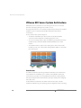
VERSION 2.5
™
Administration Guide
Please note that you will always find the most up-to-date technical documentation on our Web site at http://www.vmware.com/support/.
VMware, Inc.
3145 Porter Drive
Palo Alto, CA 94304
www.vmware.com
The VMware Web site also provides the latest product updates.
Copyright © 1998-2004 VMware, Inc. All rights reserved. Protected by one or more of U.S. Patent Nos.
6,397,242, 6,496,847, 6,704,925, 6,711,672, 6,725,289, 6,735,601, 6,785,886, 6,789,156 and 6,795,966; patents
pending. VMware is a registered trademark and the VMware boxes logo, GSX Server, ESX Server, Virtual SMP,
VMotion and VMware ACE are trademarks of VMware, Inc. Microsoft, Windows, and Windows NT are registered
trademarks of Microsoft Corporation. Linux is a registered trademark of Linus Torvalds. All other marks and
names mentioned herein may be trademarks of their respective companies. Revision: 20041129.
Item: ESX-ENG-Q304-002
Table of Contents
Introduction to VMware ESX Server ______________________________ 13
VMware ESX Server System Architecture _____________________________14
Virtualization ________________________________________________14
Service Console ______________________________________________18
Using VMware ESX Server _________________________________________21
Familiarizing Yourself with ESX Server _____________________________21
Working With ESX Server _______________________________________25
Where to Find More Information ___________________________________29
Creating and Configuring Virtual Machines _______________________ 31
Creating a New Virtual Machine ____________________________________32
Installing a Guest Operating System and VMware Tools __________________40
Installing a Guest Operating System in a Virtual Machine ______________40
Installing VMware Tools in the Guest Operating System _______________41
About the VMware Guest Operating System Service __________________46
Using PXE with Virtual Machines ___________________________________52
Configuring a Virtual Machine to Use the LSI Logic SCSI Adapter ___________54
Adding the Adapter to the Virtual Machine’s Configuration File _________54
Configuring the LSI Logic SCSI Adapter in a Windows
Guest Operating System _______________________________________56
Configuring the LSI Logic SCSI Adapter in a Linux Guest Operating System 57
Importing, Upgrading and Exporting Virtual Machines __________________59
Configuring a Virtual Machine to Use More than One Virtual Processor ___59
Migrating Older ESX Server Virtual Machines ________________________61
Migrating VMware Workstation and VMware GSX Server Virtual Machines _62
Exporting Virtual Machines _____________________________________67
Preparing to Use the Remote Management Software ___________________69
Registering Your Virtual Machines ________________________________69
Installing the Remote Console Software ______________________________70
Windows Clients _____________________________________________70
Linux – RPM Installer __________________________________________70
Linux – Tar Installer ____________________________________________70
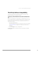
Third Party Software Compatibility __________________________________71
Configuring a Virtual Machine for Use with Citrix MetaFrame XP ________71
3
Executing Scripts When the Virtual Machine’s Power State Changes ________72
Issues to Consider ____________________________________________73
Configuring Virtual Machines ______________________________________74
Recommended Configuration Options ____________________________75
Modifying the SMBIOS UUID ____________________________________76
Enabling the Physical Hardware’s OEM ID to Be Seen by the
Virtual Machine ______________________________________________80
Using the VMware Management Interface to Manage Your Virtual
Machines ____________________________________________________ 81
Running the VMware Management Interface _________________________83
Configuring the Statistics Period for the VMware Management Interface ____85
Using Internet Explorer 6.0 to Access the VMware Management Interface ___86
Launching the Remote Console from the Management Interface on an
Encrypted Server _____________________________________________86
Connecting to the Management Interface On a Proxy Server ___________87
Logging Into the VMware Management Interface ______________________88
Using the Status Monitor _________________________________________90
Viewing Summary Information about VMware ESX Server _____________90
Viewing Summary Information about Virtual Machines on
VMware ESX Server ___________________________________________91
Connecting to a Virtual Machine with the VMware Remote Console _____91
Using the Virtual Machine Menu _________________________________92
Changing the Power State of a Virtual Machine ______________________93
Suspending and Resuming Virtual Machines ________________________94
Viewing Information about a Virtual Machine ______________________ 100
Downloading Remote Management Packages _____________________101
Creating a New Virtual Machine ________________________________ 101
Unregistering a Virtual Machine _________________________________ 101
Deleting a Virtual Machine _____________________________________ 101
Configuring VMware ESX Server ________________________________ 101
Using Common Controls ______________________________________ 101
Configuring a Virtual Machine ____________________________________ 103
Editing a Virtual Machine’s Configuration _________________________ 105
Configuring a Virtual Machine’s CPU Usage ________________________ 105
Configuring a Virtual Machine’s Memory Usage ____________________ 107
Configuring a Virtual Machine’s Disk Usage ________________________ 110
Configuring a Virtual Machine’s Networking Settings ________________ 111
4
www.vmware.com
Configuring a Virtual Machine’s Hardware _________________________113
Setting Standard Virtual Machine Configuration Options _____________133
Setting Startup and Shutdown Options for a Virtual Machine __________134
Viewing a List of Connected Users _______________________________140
Viewing a Log of a Virtual Machine’s Events ________________________141
Modifying Virtual Machine Peripherals ______________________________143
Adding More than Six SCSI Virtual Disks to a Virtual Machine __________143
Using a Physical (Raw) Disk in a Virtual Machine ____________________144
Using Parallel Ports in a Virtual Machine __________________________145
Using Serial Ports in a Virtual Machine ____________________________146
Using Disk Modes ___________________________________________147
Deleting a Virtual Machine Using the VMware Management Interface _____149
Managing ESX Server Resources ___________________________________151
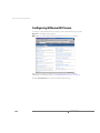
Configuring VMware ESX Server ___________________________________152
Logging Out of the VMware Management Interface ___________________153
Using the Apache Web Server with the Management Interface __________154
Setting a MIME Type to Launch the VMware Remote Console ____________155
Setting the MIME Type in Netscape 7.0 and Mozilla 1.x _______________155
Editing a Virtual Machine’s Configuration File Directly __________________157
Changing Your Virtual SCSI Adapter ______________________________157
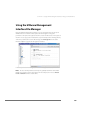
Using the VMware Management Interface File Manager ________________159
Setting Permissions for Owners of Virtual Machines _________________162
Registering and Unregistering Virtual Machines _______________________164
Registering a Virtual Machine __________________________________164
Unregistering a Virtual Machine _________________________________165
Running Many Virtual Machines on ESX Server _______________________166
Increasing the Memory in the Service Console _____________________166
Allocating CPU Resources to the Management Interface _____________166
Changing Default Parameters in the config File _____________________167
Avoiding Management Interface Failures when Many Virtual Machines
Are Registered ______________________________________________169
Backing Up Virtual Machines _____________________________________170
Using Tape Drives with VMware ESX Server ________________________170
Backing Up from within a Virtual Machine _________________________170
Backing Up Virtual Machines from the Service Console _______________171
Using Hardware or Software Disk Snapshots _______________________171
Using Network-based Replication Tools ___________________________172
5
Using the VMware Remote Console _____________________________ 175
Using the Remote Console _______________________________________ 176
Starting the Remote Console on Windows ________________________ 176
Starting the Remote Console on Linux ___________________________ 176
Running a Virtual Machine Using the Remote Console _______________ 177
Special Power Options for Virtual Machines ________________________ 178
VMware Tools Settings ________________________________________ 180
Installing New Software Inside the Virtual Machine __________________ 184
Cutting, Copying and Pasting __________________________________ 185
Suspending and Resuming Virtual Machines _______________________ 185
Shutting Down a Virtual Machine _______________________________187
Using the VMware Service Console _____________________________ 189
Characteristics of the VMware Service Console _______________________ 190
Using DHCP for the Service Console _____________________________ 190
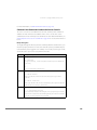
Managing the Service Console ____________________________________ 191
Connecting to the Service Console ______________________________ 191
Commands Specific to ESX Server _______________________________191
Common Linux Commands Used on the Service Console ____________ 193
Authentication and Security Features _______________________________203
Authenticating Users _________________________________________203
Default Permissions __________________________________________ 205
TCP/IP Ports for Management Access ____________________________ 205
Using Devices With ESX Server ____________________________________ 207
Supporting Generic Tape and Media Changers _____________________207
Editing the vmware-device.map.local File _________________________ 207
Finding Disk Controllers _______________________________________ 207
When You Change Storage Adapters _____________________________ 208
Enabling Users to View Virtual Machines Through the
VMware Remote Console ________________________________________ 209
Administering ESX Server _____________________________________ 211
Modifying VMware ESX Server ____________________________________ 212
Updating the Startup Profile ___________________________________ 214
Changing Network Connections ________________________________ 215
Configuring Physical Adapters __________________________________ 217
Changing Users and Groups ___________________________________ 219
Configuring Security Settings __________________________________ 224
Configuring the SNMP Agent __________________________________ 226
6
www.vmware.com
Viewing the License and Changing Serial Numbers _________________227
Configuring Storage Area Networks _____________________________227
Adapter Bindings ____________________________________________232
Viewing Failover Paths Connections _____________________________234
Configuring a Swap File _______________________________________236
Changing Advanced Settings __________________________________237
Configuring the Service Console ________________________________238
Viewing System Logs and Reports _______________________________241
Seeing How Memory Is Utilized ___________________________________246
Configuring Startup and Shutdown Options for Virtual Machines _________250
System Configuration Settings _________________________________250
Enabling the System’s Configuration Settings ______________________251
Disabling the System’s Configuration Settings ______________________254
Specifying the Order in which Virtual Machines Start ________________254
Rebooting or Shutting Down the Server ____________________________256
Using SNMP with ESX Server __________________________________ 259
Using SNMP to Monitor the Computer Running ESX Server ______________260
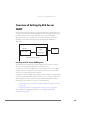
Overview of Setting Up ESX Server SNMP ___________________________263
Installing the ESX Server SNMP Agents ___________________________263
Configuring the ESX Server Agent _________________________________264
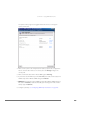
Configuring the ESX Server Agent through the VMware Management
Interface ___________________________________________________264
Configuring the ESX Server Agent from the Service Console __________266
Configuring SNMP _____________________________________________268
Configuring SNMP Trap Destinations _____________________________268
Configuring SNMP Management Client Software ___________________268
Configuring SNMP Security ____________________________________268
Using SNMP with Guest Operating Systems _______________________269
VMware ESX Server SNMP Variables ________________________________270
Using VMkernel Device Modules _______________________________ 277
Configuring Your Server to Use VMkernel Device Modules ______________278
Loading VMkernel Device Modules ______________________________278
VMkernel Module Loader ______________________________________278
Other Information about VMkernel Modules _______________________281
Controlling VMkernel Module Loading During Bootup _________________282
Customizing Parameters of VMkernel Device Driver Modules on Bootup _282
Customizing Loading of VMkernel Device Driver Modules on Bootup ___283
7
Storage and File Systems ______________________________________ 285
File System Management on SCSI Disks and RAID _____________________286
Viewing and Manipulating Files in the /vmfs Directory _______________ 287
VMFS Volumes ______________________________________________ 287
Labelling VMFS Volumes ______________________________________ 288
VMFS Accessibility ___________________________________________ 288
Changing Storage Configuration Options _________________________ 289
Using vmkfstools ______________________________________________ 290
vmkfstools Command Syntax __________________________________ 290
vmkfstools Options __________________________________________ 291
Basic vmkfstools Options ______________________________________ 291
Advanced vmkfstools Options __________________________________ 294
Examples Using vmkfstools ____________________________________ 299
Accessing Raw SCSI Disks ________________________________________ 302
Using a Physical Disk in a Virtual Machine _________________________ 302
Determining SCSI Target IDs ______________________________________ 306
Sharing the SCSI Bus ____________________________________________ 308
Setting Bus Sharing Options ___________________________________ 308
Using Storage Area Networks with ESX Server ________________________ 310
Understanding Storage Arrays __________________________________ 310
Installing ESX Server with Attached SANs _________________________ 310
Configuring VMFS Volumes on SANs _____________________________ 311
Scanning for Devices and LUNs _________________________________ 311
Changing VMkernel Configuration Options for SANs ________________ 311
Troubleshooting SAN Issues with ESX Server _______________________ 313
Using Persistent Bindings ________________________________________ 315
Determining Target IDs through the Service Console ________________ 315
pbind.pl Script ______________________________________________ 316
Examples Using the pbind.pl Script ______________________________ 317
Using Multipathing in ESX Server __________________________________ 318
Choosing Path Management Tools ______________________________ 319
Viewing the Current Multipathing State __________________________ 319
Setting Your Multipathing Policy for a LUN ________________________ 321
Specifying Paths _____________________________________________ 321
Saving Your Multipathing Settings _______________________________322
In Case of Failover ___________________________________________ 322
8
www.vmware.com
Configuration for Clustering ___________________________________ 325
What Is Clustering? _____________________________________________326
Applications that Can Use Clustering _____________________________326
Clustering Software __________________________________________326
Clustering Hardware _________________________________________327
Clustering Virtual Machines ______________________________________328
Clustering Software in Virtual Machines __________________________328
Configuring Virtual Machine Clusters with Shared Disks ______________330
Two Node Cluster with Microsoft Cluster Service on a Single ESX Server
Machine ___________________________________________________331
Two Nodes with Microsoft Cluster Service on Separate ESX Server
Machines __________________________________________________338
VMFS Locking and SCSI Reservation _____________________________346
Network Load Balancing _________________________________________349
What Is Network Load Balancing? _______________________________349
Creating Multinode Network Load Balancing Clusters on ESX Server ____349
Networking _________________________________________________ 357
Setting the MAC Address Manually for a Virtual Machine ________________358
How VMware ESX Server Generates MAC Addresses _________________358
Setting MAC Addresses Manually _______________________________359
Using MAC Addresses ________________________________________360
The VMkernel Network Card Locator _______________________________361
findnic Command ___________________________________________361
Forcing the Network Driver to Use a Specific Speed ____________________363
Enabling a Virtual Adapter to Use Promiscuous Mode __________________364
Sharing Network Adapters and Virtual Networks ______________________365
Allowing the Service Console to Use the Virtual Machines’ Devices _____365
Starting Shared VMkernel Network Adapters and Virtual Networks
when the Service Console Boots ________________________________366
Sharing the Service Console’s Network Adapter with Virtual Machines ___367
Using Virtual Switches __________________________________________369
Choosing a Network Label _____________________________________369
Binding Physical Adapters _____________________________________369
Creating a Virtual Switch ______________________________________370
Choosing a Load Balancing Mode _______________________________371
Configuring the Bond Failure Mode ______________________________371
Using Beacon Monitoring _____________________________________372
9
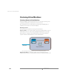
Configuring External Network Switches __________________________ 374
Troubleshooting ____________________________________________ 375
VMware ESX Server Resource Management ______________________ 377
Virtual Machine Resource Management _____________________________ 379
Service Console Resource Management __________________________ 379
Using ESX Server Resource Variables _______________________________380
Improving Performance _________________________________________382
CPU Resource Management ______________________________________ 384
Allocating CPU Resources _____________________________________ 384
Admission Control Policy ______________________________________ 385
Specifying Minimum and Maximum CPU Percentages _______________ 385
Assigning Virtual Machines to Run on Specific Processors _____________ 386
Using Proportional-share Scheduling by Allocating Shares ____________ 387
Managing CPU Time with Percentages and Shares __________________ 388
Using Hyper-Threading _______________________________________ 389
Managing Virtual Machine CPU Resources ___________________________ 390
Managing CPU Resources from the Management Interface ___________ 390
Managing CPU Resources from the Service Console _________________ 391
Memory Resource Management __________________________________ 399
Allocating Memory Resources __________________________________ 399
Setting Memory Minimum, Maximum, and Shares __________________ 400
Admission Control Policy ______________________________________ 401
Allocating Memory Dynamically ________________________________ 402
Reclaiming Memory from Virtual Machines ________________________ 403
Sharing Memory Across Virtual Machines _________________________ 404
Managing Virtual Machine Memory ________________________________ 406
Managing Memory Resources from the Management Interface ________ 406
Managing Memory Resources from the Service Console _____________ 407
Using Your NUMA System ________________________________________ 414
NUMA Configuration Information _______________________________414
Automatic NUMA Optimizations ________________________________ 416
Manual NUMA Optimizations __________________________________ 416
Sizing Memory on the Server _____________________________________ 420
Server Memory _____________________________________________ 420
Service Console Memory ______________________________________ 420
Virtual Machine Memory Pool __________________________________ 420
Virtual Machine Memory ______________________________________ 421
10
www.vmware.com
Memory Sharing ____________________________________________421
Memory Overcommitment ____________________________________422
Example: Web Server Consolidation _____________________________423
More Information ____________________________________________423
Managing Network Bandwidth ____________________________________424
Using Network Filters _________________________________________424
Managing Network Bandwidth from the Management Interface _______424
Managing Network Bandwidth from the Service Console _____________425
Traffic Shaping with nfshaper ___________________________________426
Managing Disk Bandwidth _______________________________________428
Allocation Policy ____________________________________________428
Managing Disk Bandwidth from the Management Interface ___________429
Configuration File Options _____________________________________429
Managing Disk Bandwidth from the Service Console ________________430
11
12
www.vmware.com
CHAPTER
Introduction to VMware ESX
Server
1
This VMware ESX Server Administration Guide provides information on how to use
VMware ESX ServerTM once it has been installed. For information on installing ESX
Server, refer to the VMware ESX Server Installation Guide.
This chapter contains the following sections:
• VMware ESX Server System Architecture on page 14
• Using VMware ESX Server on page 21
13
VMware ESX Server Administration Guide
VMware ESX Server System Architecture
VMware ESX Server incorporates a resource manager and a service console that
provides bootstrapping, management and other services.
The design of the ESX Server core architecture implements the abstractions that allow
hardware resources to be allocated to multiple workloads in fully isolated
environments.
The key elements of the system’s design are:
• The VMware virtualization layer, which provides the idealized hardware
environment and virtualization of underlying physical resources
• The resource manager, which enables the partitioning and guaranteed delivery
of CPU, memory, network bandwidth and disk bandwidth to each virtual
machine
• The hardware interface components, including device drivers, which enable
hardware-specific service delivery while hiding hardware differences from other
parts of the system.
Virtualization
The VMware virtualization layer brings hardware virtualization to the standard Intel
server platform. The virtualization layer is common among VMware desktop and
server products, providing a consistent platform for development, testing, delivery
and support of application workloads from the developer desktop to the workgroup
to the data center.
As with mainframe virtualization, the VMware virtual machine offers complete
hardware virtualization; the guest operating system and applications (those operating
14
www.vmware.com
C H A P T E R 1 Introduction to VMware ESX Server
inside a virtual machine) can never directly determine which specific underlying
physical resources they are accessing, such as which CPU they are running on in a
multiprocessor system or which physical memory is mapped to their pages. The
virtualization of the CPU incorporates direct execution: non-privileged instructions are
executed by the hardware CPU without overheads introduced by emulation.
The virtualization layer provides an idealized physical machine that is isolated from
other virtual machines on the system. It provides the virtual devices that map to
shares of specific physical devices; these devices include virtualized CPU, memory, I/O
buses, network interfaces, storage adapters and devices, human interface devices,
BIOS and others.
Each virtual machine runs its own operating system and applications; they cannot talk
to each other or leak data, other than via networking mechanisms similar to those
used to connect separate physical machines. This isolation leads many users of
VMware software to build internal firewalls or other network isolation environments,
allowing some virtual machines to connect to the outside while others are connected
only via virtual networks through other virtual machines.
CPU Virtualization
Each virtual machine appears to run on its own CPU, or set of CPUs, fully isolated from
other virtual machines, with its own registers, translation lookaside buffer, and other
control structures. Most instructions are directly executed on the physical CPU,
allowing compute-intensive workloads to run at near-native speed. Privileged
instructions are performed safely by the patented and patent-pending technology in
the virtualization layer.
Memory Virtualization
While a contiguous memory space is visible to each virtual machine, the physical
memory allocated may not be contiguous. Instead, noncontiguous physical pages are
remapped efficiently and presented to each virtual machine. Some of the physical
memory of a virtual machine may in fact be mapped to shared pages, or to pages that
are unmapped or swapped out. This virtual memory management is performed by
ESX Server without the knowledge of the guest operating system and without
interfering with its memory management subsystem.
Disk Virtualization
Support of disk devices in ESX Server is an example of the product’s hardware
independence. Each virtual disk is presented as a SCSI drive connected to a SCSI
adapter. This device is the only disk storage controller used by the guest operating
15
VMware ESX Server Administration Guide
system, despite the wide variety of SCSI, RAID and Fibre Channel adapters that might
actually be used in the system.
This abstraction makes virtual machines at once more robust and more transportable.
There is no need to worry about the variety of potentially destabilizing drivers that
may need to be installed on guest operating systems, and the file that encapsulates a
virtual disk is identical no matter what underlying controller or disk drive is used.
VMware ESX Server can be used effectively with storage area networks (SANs). ESX
Server supports QLogic and Emulex host bus adapters, which allow an ESX Server
computer to be connected to a SAN and to see the disk arrays on the SAN.
Network Virtualization
You may define up to four virtual network cards within each virtual machine. Each
virtual network card has its own MAC address and may have its own IP address (or
multiple addresses) as well. Virtual network interfaces from multiple virtual machines
may be connected to a virtual switch. Each virtual switch may be configured as a
purely virtual network with no connection to a physical LAN, or may be bridged to a
physical LAN via one or more of the physical NICs on the host machine.
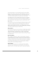
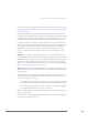
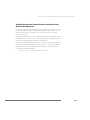
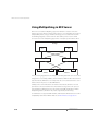
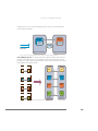
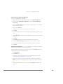
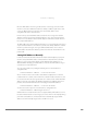
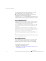
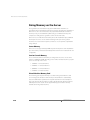
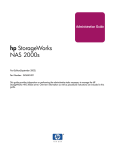
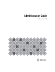
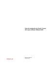
Private Virtual Ethernet Networks (VMnets)
VMnet connections may be used for high-speed networking between virtual
machines, allowing private, cost-effective connections between virtual machines. The
isolation inherent in their design makes them especially useful for supporting network
topologies that normally depend on the use of additional hardware to provide
security and isolation.
Physical
NICNIC
Virtual
machine 2
External
Web server
Virtual
machine 3
Firewall
16
vmnic0
Virtual
machine 1
Firewall
vmnet_0
vmnet_1
Internal
Virtual
Network
machine 4
On
internal
Virtual
network
Machine
www.vmware.com
C H A P T E R 1 Introduction to VMware ESX Server
For example, an effective firewall can be constructed by configuring one virtual
machine on an ESX Server system with two virtual Ethernet adapters, one bound to a
VMnic (giving it a connection to a physical network) and the other bound to a VMnet.
Other virtual machines would be connected only to the VMnet. By running filtering
software in the dual-homed virtual machine, a user can construct an effective firewall
without the need for additional hardware and with high-performance virtual
networking between the virtual machines.
A similar approach can be used with multitier applications — with the Web or
application servers reachable from other systems but with the database server
connected only to the other tiers.
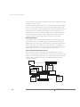
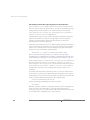
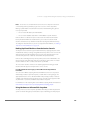
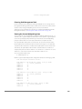
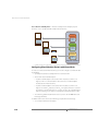
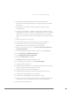
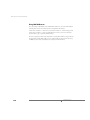
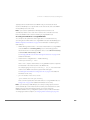
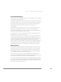
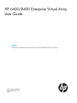
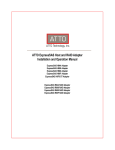
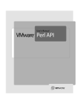
Virtualization at a Glance
ESX Server virtualizes the resources of the physical system for use by the virtual
machines.
Virtual machine 1
Virtual machine 2
CPU
Memory
Disk
NIC
NIC
CPU1
Mem1
Disk1
NIC1a
NIC1b
CPU2
Mem2
Disk2
NIC2a
NIC2b
CPU
Mem1
Mem2
Memory
Disk2
CPU1 CPU2
Disk
Physical resources
NIC2a
NIC
NIC1a
NIC
Disk2
Disk
Mem1
Memory
Disk1
CPU
NIC
NIC1b NIC2b
Virtual network
In the preceding example, each virtual machine is configured with one CPU, an
allocation of memory and disk, and two virtual Ethernet adapters. In reality, they share
the same physical CPU and access noncontiguous pages of memory (with part of the
memory of one of the virtual machines currently swapped to disk). Their virtual disks
are actually set up as files on a common file system.
Each of these example virtual machines has two virtual NICs. Virtual NICs 1a and 2a are
attached to the virtual switch that is bound to physical NICs 1a and 2a. Virtual NICs 1b
and 2b are attached to a purely virtual switch.
Software Compatibility
In the VMware ESX Server architecture, guest operating systems interact only with the
standard x86-compatible virtual hardware presented by the virtualization layer. This
provides the capability for VMware to support any x86-compatible operating system.
17
VMware ESX Server Administration Guide
In practice, however, VMware supports a subset of x86-compatible operating systems
that are tested throughout the product development cycle. VMware documents the
installation and operation of these guest operating systems and trains its technical
personnel in their support.
Because applications interact only with their guest operating system, and not the
underlying virtual hardware, once operating system compatibility with the virtual
hardware is established, application compatibility is not an issue.
Service Console
Service Console Functions
The ESX Server system management functions and interfaces are implemented in the
service console. These include the HTTP, SNMP and API interfaces described above, as
well as other support functions such as authentication and low-performance device
access. The service console is also installed as a first component and is used to
bootstrap the ESX Server installation and configuration, as well as to boot the system
and initiate execution of the virtualization layer and resource manager. In ESX Server,
the service console is implemented using a modified Linux distribution.
18
www.vmware.com
C H A P T E R 1 Introduction to VMware ESX Server
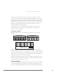
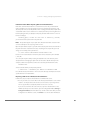
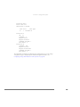
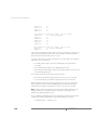
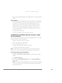
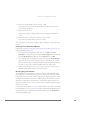
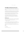
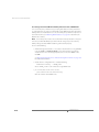
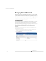
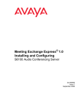
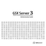
Service Console Processes and Files
The service console provides a control API that allows the virtual machines and
resource allocations to be managed. The administrator may also access these controls
via pages accessed through the Web server running in the service console.
Remote
console
API
Web browser
httpd
vmauthd
vmserverd
vmware
vmware
snmpd
mks
KVM
In addition to the Web server, the following processes and services involved in
the management of an ESX Server system run in the service console:
• Server daemon (vmserverd) — Performs actions in the service console on
behalf of the VMware Remote Console and the Web-based VMware
Management Interface.
• Authentication daemon (vmauthd) — Authenticates remote users of the
management interface and remote consoles using the username/password
database. Any other authentication store that can be accessed using the
Pluggable Authentication Module (PAM) capabilities present in the service
console may also be used. This permits the use of passwords from a Windows
domain controller, LDAP or RADIUS server, or similar central authentication store
to be used with VMware ESX Server for remote access.
• SNMP server (ucd-snmpd) — Implements the SNMP data structures and traps
an administrator can use to integrate an ESX Server system into an SNMP-based
system management tool.
19
VMware ESX Server Administration Guide
• In addition to these VMware-supplied services, the service console can be used
to run other system wide or hardware-dependent management tools. These
include hardware-specific health monitors (such as IBM Director, HP Insight
Manager and others), full-system backup and disaster recovery software, and
clustering and high availability products.
The server and virtual machine resources and configuration attributes that are
available through the SNMP and HTTP interfaces are also visible through a file system
in the service console. The files in this /proc/vmware name space may be
examined and modified by users logged in to the service console with sufficient
permissions or may be used as a point of integration for home-grown or commercial
scripts and management tools.
20
www.vmware.com
C H A P T E R 1 Introduction to VMware ESX Server
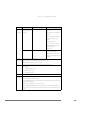
Using VMware ESX Server
VMware ESX Server contains many features to help you manage your virtual
machines’ resources. In this section, we attempt to highlight some of these features,
by listing tasks that you should perform on your ESX Server system.
The information contained in this table presumes that you have successfully installed
and configured ESX Server on your hardware. To get help, refer to the VMware ESX
Server Installation Guide.
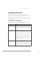
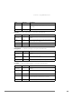
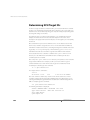
Familiarizing Yourself with ESX Server
The following table includes tasks from the VMware Management Interface for an
Administrator (root user), who manages and maintains ESX Server.
Task
Description
Log into the VMware
Management Interface and
familiarize yourself with its
features.
As the root user, you have additional privileges that other users don’t
have. In addition to the Status Monitor page, you have access to the
Options page, that allows you to configure ESX Server, including
networking, security, SNMP, users and groups, storage configuration,
and so on.
See Modifying VMware ESX Server on page 212.
Create users and groups.
Create users and place them into groups for different access to ESX
Server. For best practice, we suggest that the root user doesn’t own
virtual machines. In general, users who create, access, and modify
virtual machines don’t need to have the additional administrative
privileges of the root user.
You might choose to have a virtual machine owned by a “flagship
user” instead of a real person. By using a “flagship user,” only one user
account owns the virtual machines that are in production. An
advantage of using flagship accounts is that flagship users never
leave the company or go on vacation.
See Creating a Flagship User on page 163 and Changing Users and
Groups on page 219 for more information.
Add additional disks and
partitions, as needed.
When creating your VMFS volumes, you should keep the default
access type public, unless you plan to use your virtual machines for
clustering. If you are running clustering software, select “shared” as
your VMFS volume access type. See Configuring Storage: Disk Partitions
and File Systems on page 228 and Configuration for Clustering on
page 325 for more information.
21
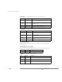
VMware ESX Server Administration Guide
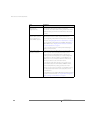
Task
Description
Decide how to organize your The default location for these files is the home directory of the user
virtual machine
that created the virtual machine. However, in production
configuration files.
environments, most virtual machines belong to teams rather than to
individuals. Setting up some kind of central directory structure is a
good idea.
Upgrade any existing virtual
machines from a previous
version of ESX Server or
another VMware product.
The migration procedure is heavily dependent on the version of the
VMware product used to create the original virtual machine.
If you are migrating a virtual machine from a previous version of ESX
Server, then see Migrating Older ESX Server Virtual Machines on page 61.
If you are migrating a virtual machine from VMware Workstation or
VMware GSX Server, see Migrating VMware Workstation and VMware
GSX Server Virtual Machines on page 62.
Be sure to read these instructions carefully, before attempting to
migrate your virtual machine.
Create “golden master”
(template) virtual disks.
To manage ESX Server more efficiently, you can create a small
number of “golden master” (template) virtual disks. for easier
deployment.These are virtual disks that have complete guest
operating systems, installed applications, complete managementagent installs, virus detection software, complete VMware Tools
installs, and so on. You can import the disks into a VMFS volume
whenever you want to create a new virtual machine.
Be sure that the golden master has the tools necessary to reset
system attributes (hostname and IP address, NetBIOS hostname,
domain and SID [Windows operating systems] for the virtual
machines you clone. Also, be sure that the user that will be running
the newly created virtual machine has the appropriate user and
group permissions.
Use the File Manager in the VMware Management Interface to import
the “golden master” virtual disks. See Using the VMware Management
Interface to Manage Your Virtual Machines on page 81.
22
www.vmware.com
C H A P T E R 1 Introduction to VMware ESX Server
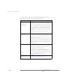
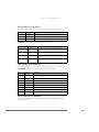
Task
Description
Set user and group
permissions for the owner of
a virtual machine.
Log into the management interface and click Manage Files. Navigate
to the configuration file (.vmx) of the virtual machine. Click the
check box next to the virtual machine’s configuration file, and click
Edit Properties. Choose read, write, and execute properties for the
owner of the virtual machine, and choose read and execute privileges
for the owner’s group, then click OK. Similarly, set read and write
permissions for the owner on the virtual machine’s virtual disk
(.vmdk file. (Note that read permissions for a virtual disk file are
sufficient if the virtual disk is nonpersistent).
See Setting Permissions for Owners of Virtual Machines on page 162 and
Using Disk Modes on page 147.
Be sure that the same user owns both the virtual machine’s
configuration and virtual disk file, and this user has full access
privileges for both files.
Set user and group
permissions to view a virtual
machine in the Status
Monitor page of the
management interface.
For a user to see a virtual machine in the management interface, the
user, or a group to which the user belongs, must have read access to
that virtual machine.
Set user permissions to
connect to a virtual machine
through the remote console.
For a user to connect to and power on a virtual machine in the
remote console the user, or a group to which the user belongs, must
have read and execute access to that virtual machine’s configuration
file. Also, the user must have execute (x) permission on all parent
directories.
See Setting Permissions for Owners of Virtual Machines on page 162.
Setting Permissions for Owners of Virtual Machines on page 162.
Configure your SNMP agent.
ESX Server ships with an SNMP agent that allows you to monitor the
health of the physical machine where ESX Server is running and of
virtual machines running on it.
See Configuring the SNMP Agent on page 226 and Configuring the ESX
Server Agent through the VMware Management Interface on page 264.
23
VMware ESX Server Administration Guide
The following table includes tasks from the VMware Management Interface for a
virtual machine user, who creates and modifies virtual machines.
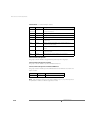
Task
Description
Log into the VMware
Management Interface and
download the remote
console package.
You can use the remote console to power on and power off your
virtual machines, connect or disconnect devices (including the CD
drive and network adapter), and set preferences (including mouse
keyboard, and hot key behavior in the remote console window).
You can install the remote console from the Status Monitor page of
the management interface. Launch the remote console from your
desktop (Windows operating systems) or from the management
interface.
Click the appropriate link for the operating system on your
workstation.
Learn to use the
management interface.
After login, the starting page of the management interface provides a
summary of the virtual machines on ESX Server. Depending on your
permissions, you’ll be able to view and modify virtual machines. See
Using the Status Monitor on page 90.
Clicking on a virtual machine’s name opens the details page for that
virtual machine, where you can check its CPU, memory, disk, network,
hardware, options, and users and events. Familiarize yourself with the
information contained in these pages. See Configuring a Virtual
Machine on page 103.
Create a virtual machine.
The Add Virtual Machine wizard only allows you to add a small
number of devices to a virtual machine. This makes the initial creation
process simpler. You may add devices later by clicking Add Device in
the Hardware page for the virtual machine.
If you have purchased the VMware Virtual SMP for ESX Server
product, then you can create dual-virtual CPU SMP virtual machines.
Be sure to take into account the type of applications you plan to run
on this virtual machine when making your choices during its creation.
See Creating a New Virtual Machine on page 32.
Add additional disks, drives,
network adapters, and SCSI
devices.
24
Click Add Device in the Hardware page for the virtual machine. See
Configuring a Virtual Machine’s Hardware on page 113.
www.vmware.com
C H A P T E R 1 Introduction to VMware ESX Server
Task
Description
Install guest operating
system and VMware Tools.
VMware Tools is a software package installed in the guest operating
system that gives you device drivers specific to VMware virtual
devices where necessary, and it also includes several communication
channels between the virtual machine and the ESX Server
virtualization layer.
See Installing a Guest Operating System and VMware Tools on page 40.
For more information about VMware Tools and the services it
provides, see VMware Tools Settings on page 180.
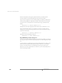
Working With ESX Server
This section includes information on maintenance tasks, performance enhancements,
and general troubleshooting tips.
The following table includes ESX Server maintenance tasks for an Administrator (root
user).
Back up your virtual
machines.
You can do backups for each virtual machine, or from the service console.
Backups from the service console are best for system images, because they
result in a backup bootable virtual disk, and are suitable for rapid
redeployment. See Backing Up from within a Virtual Machine on page 170..
Backups from within the virtual machine, using a backup agent, are best for
application data because no system shutdown is required. See Backing Up
Virtual Machines from the Service Console on page 171.
Use scripts to
schedule frequent
tasks.
For more information on VMware Scripting APIs, see
View system logs and
reports through the
management
interface.
As needed, view the ESX Server log files for warnings, serious system alerts
and messages through the management interface.
See Viewing System Logs and Reports on page 241.
25
VMware ESX Server Administration Guide
The following table includes ESX Server performance-related tasks for an
Administrator (root user).
Task
Description
Enhance performance on
virtual machines, based on
its application(s).
ESX Server applies a proportional share mechanism to CPU, memory
allocation, and disk bandwidth. Typically, the more shares a virtual
machine has, the more CPU, memory or disk bandwidth it has.
For example, virtual machines running a CPU-intensive application
should have a greater minimum CPU and memory share than a
virtual machine running a non-CPU intensive application.
For additional information on resource management, see VMware ESX
Server Resource Management on page 377.
Enhance CPU performance
on virtual machines.
You can set minimum and maximum percentages as well as memory
shares for each virtual machine. You can also select the processors on
which the virtual machine runs.
See Configuring a Virtual Machine’s CPU Usage on page 105 and CPU
Resource Management on page 384.
Enhance memory utilization
on virtual machines.
You can set memory shares for a virtual machine. If you have a NUMA
machine, you can also select the NUMA affinity nodes for the virtual
machine.
See Configuring a Virtual Machine’s Memory Usage on page 107, Memory
Resource Management on page 399, and Using Your NUMA System on
page 414.
Enhance disk bandwidth
utilization on virtual
machines.
You can set disk bandwidth for a virtual machine. A virtual machine
with more shares has more bandwidth.
Enhance networking
performance on virtual
machines.
You can manage networking performance by enabling traffic
shaping and specifying network parameters.
Remove any unnecessary
programs or services from
your virtual machines.
Remove any unnecessary programs or services, such as CPU-intensive
screensavers, from your virtual machines.
Be sure that the service
console has enough CPU
and RAM.
If you are running a lot of virtual machines on ESX server, and you
notice a degradation in system performance, then you should
increase the CPU minimum for the service console.
See Configuring a Virtual Machine’s Disk Usage on page 110 and
Managing Disk Bandwidth on page 428.
See Configuring a Virtual Machine’s Networking Settings on page 111 and
Managing Network Bandwidth on page 424.
Run Linux virtual machines without the X Window system, if possible.
Configuring the Service Console on page 238.
26
www.vmware.com
C H A P T E R 1 Introduction to VMware ESX Server
Task
Description
Be sure there is sufficient
swap space for your guest
operating system.
For resource management purposes, ESX Server may increase the
memory utilization within a guest operating system. Therefore, it is
important to ensure that the guest operating system has sufficient
swap space.
Add additional swap space in the guest operating system, equal to
the difference between the virtual machine's maximum and
minimum memory sizes.
See Admission Control Policy on page 401.
Remove any unnecessary
programs or services from
your service console.
Do not run the X Window system in your service console.
Use SNMP to watch memory, See Using SNMP with ESX Server on page 259.
resource usage, and
workloads on ESX Server and
its virtual machines.
The following table includes some general troubleshooting information.
Problem
Suggestions
Can’t start a virtual machine.
Check permissions on the virtual machine configuration file and on
the virtual disk. See Setting Permissions for Owners of Virtual Machines
on page 162.
Check that there is enough memory to power on this virtual
machine. See Sizing Memory on the Server on page 420.
Check that there is enough unreserved swap space. For more
information, see Swap Space and Guest Operating Systems on
page 404.
Check that the virtual disks are in a VMFS volume. If the virtual disk
file is from VMware Workstation or VMware GSX Server, be sure the
virtual disk has been properly imported, through the management
interface, into ESX Server. See Migrating VMware Workstation and
VMware GSX Server Virtual Machines on page 62.
Can’t connect to the VMware
Management Interface.
Check to see if there has been a loss in IP connectivity.
Check that the NIC duplex or speed matches with the Ethernet
switch.
Check that the service console is not swapping.
Check that the root file system has available disk space.
27
VMware ESX Server Administration Guide
Problem
Suggestions
Can’t connect to the VMware
Remote Console.
Check to see if there has been a loss in IP connectivity.
Check that the NIC duplex or speed matches with the Ethernet
switch.
Check that the service console is not swapping.
Check that the root file system has available disk space.
28
www.vmware.com
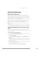
C H A P T E R 1 Introduction to VMware ESX Server
Where to Find More Information
The latest ESX Server documentation is available in the VMware Web site at
www.vmware.com/support/pubs/esx_pubs.html.
Additional technical information, covering such topics as hardware compatibility, is
available at www.vmware.com/support/resources/esx_resources.html.
29
VMware ESX Server Administration Guide
30
www.vmware.com
CHAPTER
2
Creating and Configuring Virtual
Machines
The following sections describe how to create and configure virtual machines and
install the VMware Remote Console:
• Creating a New Virtual Machine on page 32
• Installing a Guest Operating System and VMware Tools on page 40
• Using PXE with Virtual Machines on page 52
• Configuring a Virtual Machine to Use the LSI Logic SCSI Adapter on page 54
• Importing, Upgrading and Exporting Virtual Machines on page 59
• Preparing to Use the Remote Management Software on page 69
• Installing the Remote Console Software on page 70
• Third Party Software Compatibility on page 71
• Executing Scripts When the Virtual Machine’s Power State Changes on page 72
• Configuring Virtual Machines on page 74
31
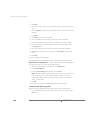
VMware ESX Server Administration Guide
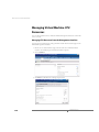
Creating a New Virtual Machine
You can create new virtual machines from within the VMware Management Interface.
The process sets up a new configuration for each virtual machine you create this way.
Note: You can only use ASCII characters in the entry fields when creating a virtual
machine with the management interface. Thus, the virtual machine’s display name
and path cannot contain non-ASCII characters. In addition, filenames and directories
for virtual machines should be not created with space characters.
The Add Virtual Machine wizard guides you through the basic steps needed to create
a virtual machine on your server. Any user who has an account on the server’s service
console may log in to the wizard and create a virtual machine. If you are logged in as
root, you may wish to log out at this point, then log in again as a user authorized to
manage the new virtual machine.
Note: Check for any VMkernel ALERT messages in the warning log files before
creating a new virtual machine.
To log in to the management interface, use this URL:
http://<hostname>
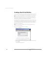
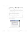
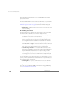
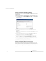
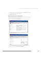
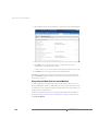
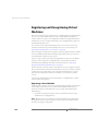
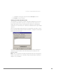
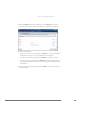
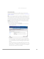
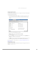
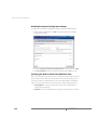
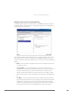
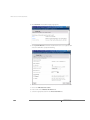
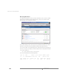
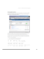
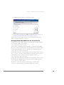
1. On the management interface login page, enter your user name and password,
then click Login.
The Status Monitor page appears.
32
www.vmware.com
C H A P T E R 2 Creating and Configuring Virtual Machines
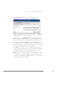
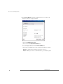
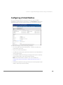
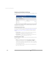
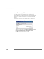
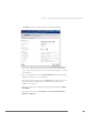
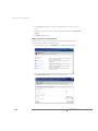
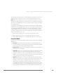
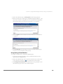
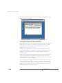
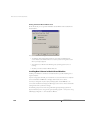
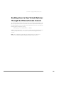
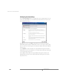
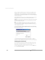
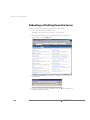
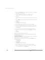
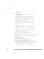
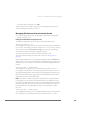
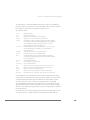
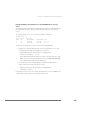
2. Click Add Virtual Machine. The Add Virtual Machine wizard starts.
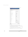
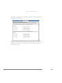
3. Choose the guest operating system for your virtual machine. Corresponding
default entries appear for the name of the virtual machine and the name of its
configuration file. You can change these settings.
The name you enter in the Display Name field is the name that is listed in the
VMware Management Interface. Be sure to enter a name that allows you to
distinguish this virtual machine from others you have created or plan to create.
Be sure that the entry in the Location field is unique. The default path and
filename are based on the guest operating system you have chosen. If other
virtual machines have been created on this server, you must change the path to
create a new, unique directory for the new virtual machine.
The Location field contains the name of the configuration file (this file has a
.vmx extension; this directory also contains other virtual machine files). Each
virtual machine must have its own directory. All associated files, such as the
configuration file and the disk files, are placed in this directory.
Note: Configuration files for virtual machines created with VMware ESX Server
2.0 and later use the .vmx extension. Earlier versions of ESX Server used the
.cfg extension. Virtual machine configuration files with a .cfg extension can
be accessed by ESX Server 2.5 normally.
33
VMware ESX Server Administration Guide
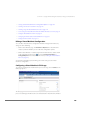
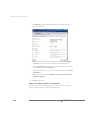
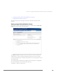
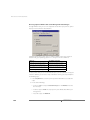
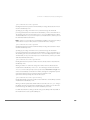
When you are ready to proceed, click Next.
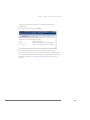
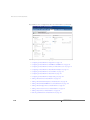
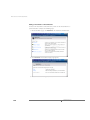
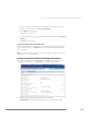
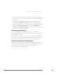
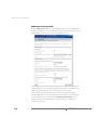
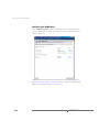
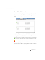
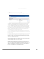
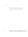
4. In the Processors list, choose the number of virtual CPUs in your virtual machine.
You may choose 1 or 2 virtual CPUs, but they must be less than or equal to the
number of physical CPUs on your server.
Note: Some guest operating systems, such as Windows NT, can be configured
with a single processor only. If you are configuring such a virtual machine, a note
indicates this and you cannot select more than one virtual CPU.
Note: You can create dual-virtual CPU virtual machines only if you have
purchased the VMware Virtual SMP for ESX Server product. For more information
on this product, contact VMware, Inc. or your authorized sales representative.
The default setting in the Memory entry field depends on the guest operating
system you have selected. You may need to change it to meet the demands of
applications you plan to run in the virtual machine. You may change this setting
later, on the virtual machine’s Memory tab in the management interface. See
Managing Memory Resources from the Management Interface on page 406.
For background on allocating memory to virtual machines, see Sizing Memory
on the Server on page 420.
In the Workloads list, select Citrix Terminal Services if you plan to run Citrix
MetaFrame on the virtual machine. This option allows ESX Server to reserve and
allocate more memory to virtual machines running Citrix MetaFrame in order to
achieve the best performance possible.
Note: Do not select this option if you do not plan to run Citrix MetaFrame on
the virtual machine. Virtual machines with this setting use more "virtualization
34
www.vmware.com
C H A P T E R 2 Creating and Configuring Virtual Machines
overhead" and ESX Server will be able to run fewer virtual machines
simultaneously.
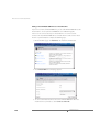
5. When you are ready to proceed, click Next.
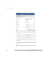
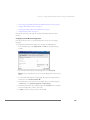
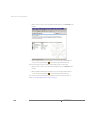
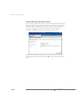
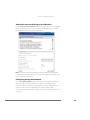
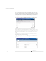
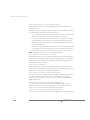
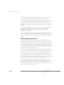
6. Choose the type of virtual disk you want to add to the virtual machine.
The setup process allows you to create one virtual disk for your virtual machine.
You can add more virtual disks later, using the virtual machine’s Hardware in the
management interface. See Configuring a Virtual Machine’s Virtual Disks on
page 120.
35
VMware ESX Server Administration Guide
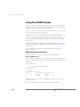
• Click Blank to create a new virtual disk. Then specify the following.
a. Choose the location for the new virtual disk. In the VMFS Volume list, choose
the volume on which to locate the virtual disk. The amount of free space is
listed next to the volume name, so you know how large you can make the
virtual disk.
b. Give the virtual disk a name. In the VMware Disk Image entry field, specify the
disk name, making sure the file has a .vmdk extension.
c. Specify the size of the virtual disk. In the Capacity entry field, specify the size
of the virtual disk in MB. The default entry indicates the lesser of either
4000MB or the amount of free space available on the volume.
d. Specify the virtual device node. Select the appropriate SCSI ID in the Virtual
SCSI Node list.
e. Choose the disk mode. Under Disk Mode, click Persistent, Nonpersistent,
Undoable or Append. For a discussion of disk modes, see Using Disk Modes
on page 147.
Note: A new virtual machine with a blank virtual disk is like a new computer
with a blank hard disk. You must install a guest operating system before you can
36
www.vmware.com
C H A P T E R 2 Creating and Configuring Virtual Machines
use the virtual machine. See Installing a Guest Operating System and VMware
Tools on page 40.
• Click Existing to add an existing virtual disk to the virtual machine. Then
specify the following.
a. Choose the location of the virtual disk you want to use. In the VMFS Volume
list, choose the volume on which the virtual disk is located.
b. In the VMware Disk Image list, select the virtual disk you want. The size of the
virtual disk appears in the Capacity field; you cannot change this value.
c. Specify the virtual device node. Select the appropriate SCSI ID in the Virtual
SCSI Node list.
d. Choose the disk mode. Under Disk Mode, click Persistent, Nonpersistent,
Undoable or Append. For a discussion of disk modes, see Using Disk Modes
on page 147.
37
VMware ESX Server Administration Guide
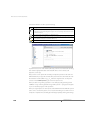
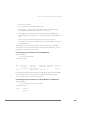
7. Click System LUN/Disk to allow the virtual machine to access a physical disk
stored on a LUN. Then specify the following.
a. Select Use Metadata to enable access to the disks metadata file information.
b. Choose the Metadata File Location.
c. Enter a name in the Metadata File Name field.
d. Select the appropriate SCSI ID in the Virtual SCSI Node list.
e. Choose the Compatibility of the guest operating system: Physical or Virtual.
Physical — gives the guest operating system direct disk access.
Virtual — allows you to choose a disk mode for the guest operating system.
38
www.vmware.com
C H A P T E R 2 Creating and Configuring Virtual Machines
8. When you are finished configuring the virtual disk, click Next. The Hardware tab
for this virtual machine appears.
You can change any of the default settings ESX Server assigned to the virtual
machine (such as the disk mode, network card, color depth and any removable
devices) or configuration items you specified as you create the virtual machine.
To change any hardware, see Configuring a Virtual Machine’s Hardware on
page 113.
39
VMware ESX Server Administration Guide
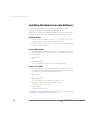
Installing a Guest Operating System and
VMware Tools
This section describes the following:
• Installing a Guest Operating System in a Virtual Machine on page 40
• Installing VMware Tools in the Guest Operating System on page 41
• About the VMware Guest Operating System Service on page 46
In most cases, you configure your virtual machine with a blank (unformatted) SCSI
virtual disk. You can install an operating system on this virtual disk just as you would
on a new physical machine, using a standard installation CD-ROM and formatting the
virtual disk at the appropriate place in the installation process.
You may also install from image files — ISO image files of installation CD-ROMs and
floppy image files of any floppy disks needed for the installation. Use the VMware
Management Interface to connect the virtual machine’s drives to the appropriate
image files before you begin the installation.
Another approach is to start with a virtual disk created with VMware Workstation 3.2
or higher or with VMware GSX Server 2.5 or higher, then configure the guest
operating system to work with VMware ESX Server.
Once your guest operating system is installed, be sure to follow the directions below
for installing VMware Tools and the network driver.
Installing a Guest Operating System in a Virtual Machine
To install a guest operating system and other software, use the VMware Remote
Console on a different system than the one on which you’ve installed ESX Server.
For details on installing the remote console, see Installing the Remote Console
Software on page 70. Follow the directions in that section for starting a remote
console on your Windows or Linux workstation and connecting to a virtual machine.
Insert the installation CD-ROM for your guest operating system in the server’s CDROM drive. Click Power On on the remote console toolbar to begin setting up your
guest operating system. See and the ESX Server 2.5 release notes for details on
installing specific guest operating systems.
If you prefer to install over a network, you need ISO image files of installation CDROMs and floppy image files of any floppy disks needed for the installation. The
installation instructions in this section assume you are installing from physical media.
If you are using image files, you should connect the virtual machine’s CD-ROM or
40
www.vmware.com
C H A P T E R 2 Creating and Configuring Virtual Machines
floppy drives to the appropriate image files before you begin installing the guest
operating system.
Note: When you are installing a guest operating system on a new virtual disk, you
may see a message warning you that the disk is corrupted and asking if you want to
place a partition table on the disk. This does not mean there is any problem with your
physical hard disk. It simply means some data needs to be written to the file that holds
your virtual hard disk. All you need to do is respond Yes. You also need to partition and
format the virtual disk as you would with a new, blank hard drive.
Installing a Guest Operating System on a Previously Formatted Raw Disk
If you try to install a guest operating system on a raw or physical disk that was
formatted previously with a file system, you might see a “No operating system” error
when you power on the virtual machine. This occurs because the boot order specified
in the virtual machine’s BIOS defaults to the floppy disk, hard disk and then the CDROM drive. Instead of booting from the installation CD-ROM, the virtual machine tries
booting from the hard disk.
To work around this issue, do one of the following:
• Change the boot order in BIOS so the virtual machine boots from the CD-ROM
drive before trying the hard disk. When the virtual machine boots, enter the BIOS
and change the boot order on the Boot menu.
• Zero out the first 64KB of the raw disk using dd or a similar utility. For example,
using dd:
# dd if=/dev/zero of=/dev/<device> count=64 bs=1024
In the command above, device is the device name of the physical disk.
Installing VMware Tools in the Guest Operating System
This section describes how to install VMware Tools and the network driver in the guest
operating system.
• Installing VMware Tools in a Windows Server 2003 Guest on page 42
• Installing VMware Tools in a Windows XP Guest on page 42
• Installing VMware Tools in a Windows 2000 Guest on page 43
• Installing VMware Tools and the Network Driver in a Windows NT 4.0 Guest on
page 43
• Installing VMware Tools in a Linux Guest on page 44
• Installing VMware Tools in a NetWare 6.0 SP3, 6.5 or 5.1 SP6 Guest on page 45
41
VMware ESX Server Administration Guide
Note the following:
• The steps for each guest operating system assume that you are working from a
remote console connected to your virtual machine.
• Prepare your virtual machine to install VMware Tools. Choose Settings >
VMware Tools Install.
This option prepares the CD-ROM drive in the virtual machine to use an ISO
image file containing the VMware Tools packages. This image, which appears as
a regular CD-ROM disk in the virtual machine, was placed on your server
machine when you installed VMware ESX Server.
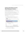
Installing VMware Tools in a Windows Server 2003 Guest
1. Choose Settings > VMware Tools Install.
This step connects the virtual machine’s CD-ROM drive to an ISO image file on
the ESX Server machine. If autorun is enabled in your guest operating system
(the default setting for Windows operating systems), a dialog box appears after a
few seconds. It asks if you want to install VMware Tools. Click Install to launch the
installation wizard.
If autorun is not enabled, the dialog box does not appear automatically. If it
doesn’t appear, run VMwareTools.exe from the CD-ROM drive (choose Start
> Run > D:\VMwareTools.exe, where D: is the first CD-ROM drive in your
virtual machine) to install VMware Tools.
2. During the installation, two Hardware Installation messages appear, stating that
the VMware SVGA and VMware Pointing Device drivers have not passed
Windows Logo testing. Accept these messages and continue.
3. Reboot the guest operating system when prompted.
When the installation completes, ESX Server disconnects the ISO image file and
returns the virtual machine’s CD-ROM drive to its original configuration.
Installing VMware Tools in a Windows XP Guest
1. Choose Settings > VMware Tools Install.
This step connects the virtual machine’s CD-ROM drive to an ISO image file on
the ESX Server machine. If autorun is enabled in your guest operating system
(the default setting for Windows operating systems), a dialog box appears after a
few seconds. It asks if you want to install VMware Tools. Click Install to launch the
installation wizard.
If autorun is not enabled, the dialog box does not appear automatically. If it
doesn’t appear, run VMwareTools.exe from the CD-ROM drive (choose Start
42
www.vmware.com
C H A P T E R 2 Creating and Configuring Virtual Machines
> Run > D:\VMwareTools.exe, where D: is the first CD-ROM drive in your
virtual machine) to install VMware Tools.
2. During the installation, two Hardware Installation messages appear, stating that
the VMware SVGA and VMware Pointing Device drivers have not passed
Windows Logo testing. Accept these messages and continue.
3. Reboot the guest operating system when prompted.
When the installation completes, ESX Server disconnects the ISO image file and
returns the virtual machine’s CD-ROM drive to its original configuration.
Installing VMware Tools in a Windows 2000 Guest
1. Choose Settings > VMware Tools Install.
This step connects the virtual machine’s CD-ROM drive to an ISO image file on
the ESX Server machine. If autorun is enabled in your guest operating system
(the default setting for Windows operating systems), a dialog box appears after a
few seconds. It asks if you want to install VMware Tools. Click Install to launch the
installation wizard.
If autorun is not enabled, the dialog box does not appear automatically. If it
doesn’t appear, run VMwareTools.exe from the CD-ROM drive (Start > Run
> D:\VMwareTools.exe, where D: is the first CD-ROM drive in your virtual
machine) to install VMware Tools.
2. When installation is complete, choose Settings > Cancel Tools Install to
disconnect the ISO image file and return the virtual machine’s CD-ROM drive to
its original configuration.
Installing VMware Tools and the Network Driver in a Windows NT 4.0 Guest
1. Choose Settings > VMware Tools Install.
This step connects the virtual machine’s CD-ROM drive to an ISO image file on
the ESX Server machine. If autorun is enabled in your guest operating system
(the default setting for Windows operating systems), a dialog box appears after a
few seconds. It asks if you want to install VMware Tools. Click Install to launch the
installation wizard.
If autorun is not enabled, the dialog box does not appear automatically. If it
doesn’t appear, run VMwareTools.exe from the CD-ROM drive (choose Start
> Run > D:\VMwareTools.exe, where D: is the first CD-ROM drive in your
virtual machine) to install VMware Tools.
2. Do one of the following:
43
VMware ESX Server Administration Guide
• If you configured this virtual machine to use the vlance network driver, go
to step 5.
• If you configured this virtual machine to use the vmxnet network driver,
choose Start > Control Panel > Network > Adapters and click Add.
3. Click Have Disk and enter D:\Program files\VMware\VMware
Tools\Drivers\vmxnet\winnt in the Insert Disk dialog (where D: is the
first CD-ROM drive in your virtual machine). Click OK when VMware Virtual
Ethernet Adapter is displayed in the Select OEM Option dialog. The VMware
network driver is installed.
4. Click Close in the Adapters dialog box to complete the installation. Windows lets
you configure the Internet address for the card.
If you are installing on a virtual machine that was created with VMware
Workstation and used networking, you must use an address different from the
one the original network configuration used (since that address is still assigned
to the now nonexistent virtual AMD card). Or you can change the address
assigned to the AMD card at this point.
Note: The VMware Virtual Ethernet Adapter driver runs correctly only if you
have Service Pack 3 or later installed. If you do not have the proper service pack
installed yet, you may get an error message such as:
System Process Driver Entry Point Not Found; The
\SystemRoot\System32\drivers\vmxnet.sys device driver
could not locate the entry point NdisGetFirstBufferFromPacket
in driver NDIS.SYS.
However, even if you get this message, the driver should work if you
subsequently install the correct service pack.
5. When installation is complete, and before you reboot, choose Settings > Cancel
Tools Install to disconnect the ISO image file and return the virtual machine’s
CD-ROM drive to its original configuration.
6. Reboot the virtual machine.
Installing VMware Tools in a Linux Guest
1. Choose Settings > VMware Tools Install, then click Install.
This step connects the virtual machine’s CD-ROM drive to an ISO image file on
the ESX Server machine.
2. In your Linux guest, become root, mount the VMware Tools virtual CD-ROM,
copy the installer file from the virtual CD-ROM to /tmp, then unmount the CDROM.
44
www.vmware.com
C H A P T E R 2 Creating and Configuring Virtual Machines
su
mount -t iso9660 /dev/cdrom /mnt
cp /mnt/vmware-linux-tools.tar.gz /tmp
umount /dev/cdrom
3. Untar the VMware Tools tar file in /tmp and install it.
cd /tmp
tar zxf vmware-linux-tools.tar.gz
cd vmware-tools-distrib
./vmware-install.pl
Note: When installing VMware Tools in some versions of Linux, the installer will
need to recompile VMware Tools. For this to work, you need to have a C compiler
installed in the guest. In some cases you may get compiler warning messages
during the VMware Tools installation. However, the control panel and drivers still
work correctly.
4. Follow the remaining steps. Choose directories for the various files.
5. Choose a display size for the virtual machine. Enter the number for the choice
and press Enter.
6. If you wish, start X and your graphical environment and launch the VMware
Tools background application.
vmware-toolbox &
Note: If you created this virtual machine using the vmxnet driver, you now
need to run netconfig or another network configuration utility in the virtual
machine to set up the virtual network adapter.
Installing VMware Tools in a NetWare 6.0 SP3, 6.5 or 5.1 SP6 Guest
1. Power on the virtual machine.
2. Prepare your virtual machine to install VMware Tools.
Choose File > Install VMware Tools.
The remaining steps take place inside the virtual machine.
3. Load the CD-ROM driver so the CD-ROM device mounts the ISO image as a
volume. Do one of the following:
a. In the system console for a NetWare 6.5 virtual machine, type:
LOAD CDROM
b. In the system console for a NetWare 5.1 virtual machine, type:
LOAD CD9660.NSS
45
VMware ESX Server Administration Guide
4. When the driver finishes loading, you can begin installing VMware Tools. In the
system console, type:
vmwtools:\setup.ncf
5. When the installation finishes, the message VMware Tools for NetWare are now
running appears in the Logger Screen (NetWare 6.5 guests) or the Console
Screen (NetWare 5.1 guests).
6. Restart the guest operating system. In the system console, type:
restart server
After you install VMware Tools, make sure the VMware Tools virtual CD-ROM
image (netware.iso) is not attached to the virtual machine. If it is,
disconnect it. Right-click the CD-ROM icon in the status bar of the console
window and select Disconnect.
Starting VMware Tools Automatically
You may find it helpful to configure your guest operating system so VMware Tools
starts when you start X. The steps for doing so vary depending on your Linux
distribution and the desktop environment you are running. Check your operating
system documentation for the appropriate steps to take.
For example, in a Red Hat Linux 7.1 guest using GNOME, follow these steps.
1. Open the Startup Programs panel in the GNOME Control Center.
Main Menu (the foot in the lower left corner of the screen) > Programs >
Settings > Session > Startup Programs
2. Click Add.
3. In the Startup Command field, enter vmware-toolbox.
4. Click OK, click OK again, then close the GNOME Control Center.
The next time you start X, VMware Tools start automatically.
About the VMware Guest Operating System Service
When you install VMware Tools in a virtual machine, the VMware guest operating
system service is one of the primary components installed. The guest service can do
the following:
• Synchronize the time of the guest operating system with the time on the
physical computer. See Synchronizing the Time Between the Guest and Service
Consoles on page 47.
46
www.vmware.com
C H A P T E R 2 Creating and Configuring Virtual Machines
• Gracefully power off and reset a virtual machine. See Shutting Down and
Restarting a Virtual Machine on page 48.
• Execute commands in the virtual machine when it is requested to halt or reboot
the guest operating system. See Executing Commands When ESX Server
Requests the Guest Service to Halt or Reboot a Virtual Machine on page 49.
• Pass a string from the service console to the guest operating system. See Passing
a String from the Service Console to the Guest Operating System on page 49.
• Send a heartbeat to VMware ESX Server so that it knows the guest operating
system is running.
The guest service starts automatically when you boot the guest operating system.
In a Linux guest, the guest service is called vmware-guestd. To display help about
the guest service, including a list of all options, use the following command:
/etc/vmware/vmware-guestd --help
In a Windows guest, the guest service program file is called VMwareService.exe.
To display help, right-click the VMware Tools icon in the system tray and choose Help.
Synchronizing the Time Between the Guest and Service Consoles
The guest service can synchronize the date and time in the guest operating system
with the time in the service console once every second. In the VMware Tools control
panel, on the Other tab (Options in a Linux guest), select Time synchronization
between the virtual machine and the host operating system.
47
VMware ESX Server Administration Guide
In addition, the guest service can synchronize the date and time in the guest with the
service console in response to various system events — for example, when you
resume from disk. You can disable this in the configuration file by setting:
time.synchronize.resume.disk = FALSE
Shutting Down and Restarting a Virtual Machine
ESX Server can signal the guest service to shut down or restart a virtual machine. After
the guest service receives a request to shut down or restart, it sends an
acknowledgment back to ESX Server.
You can send these requests from the VMware Management Interface or the service
console’s command line.
Whether it is possible to shut down or restart a virtual machine depends on the state
of the virtual machine.
Shutting Down or Restarting a Virtual Machine from the VMware Management
Interface
You can click to shut down or
to restart a virtual machine from the VMware
Management Interface. After you select one of these operations, you should click to
the Users and Events page for this virtual machine to respond to any messages that
require a response.
Shutting down is the equivalent of using the guest operating system’s shut down
command, then turning off power to the virtual machine. Restarting is the equivalent
of using the guest operating system’s restart command.
If you receive an event log message saying, “You will need to power off or reset the
virtual machine at this point,” you must connect to the virtual machine with a remote
console and click Power Off or Reset to complete the operation.
The power off and reset commands are not available while these operations are in
progress.
You can also force power off or force reset from the menu. These commands bypass
the guest service and perform the virtual equivalent of shutting off the power to a
physical machine or pressing a physical reset button.
For more information, see Changing the Power State of a Virtual Machine on page 93.
Shutting Down or Restarting a Virtual Machine from the Command Line
You can shut down and restart a virtual machine from the service console command
line using the vmware-cmd utility.
48
www.vmware.com
C H A P T E R 2 Creating and Configuring Virtual Machines
The following commands return you to the command prompt immediately, before
they finish executing, although the shut down or restart process may take some time
to complete:
vmware-cmd <vm-cfg-path> stop <powerop_mode>
vmware-cmd <vm-cfg-path> reset <powerop_mode>
where hard, soft or trysoft specifies the behavior of the power operation
<powerop_mode>. If <powerop_mode> is not specified, the default behavior is soft.
For more information, see the VMware Scripting API User’s Manual.
Executing Commands When ESX Server Requests the Guest Service to Halt or
Reboot a Virtual Machine
In a Linux guest, you can have the guest service execute specific commands when
ESX Server asks it to halt or reboot the virtual machine’s guest operating system. If you
use nonstandard utilities or want to do additional things before shutting down or
rebooting the guest operating system, you can override the default commands the
guest service executes by modifying the /etc/vmware/dualconf.vm startup
script in the guest to start the guest service with the following command line options:
/etc/vmware/vmware-guestd --halt-command <command>
where <command> is the command to execute when ESX Server asks the guest
service to halt the guest operating system
/etc/vmware/vmware-guestd --reboot-command <command>
where <command> is the command to execute when ESX Server asks the guest
service to reboot the guest operating system
Passing a String from the Service Console to the Guest Operating System
With ESX Server and knowledge of a scripting language like Perl or NetShell (in a
Windows 2000 guest operating system), you can pass a string from your virtual
machine’s configuration file to the guest operating system when you use the
configuration file to launch a virtual machine. This string is known as machine.id.
The content of the string you pass to the guest operating system is up to you.
For additional details and sample scripts, including information on passing messages
both ways between the service console and a guest, see the VMware Scripting API
documentation at http://www.vmware.com/support/developer/.
You should use this feature only if you have a good understanding of a scripting
language and know how to modify system startup scripts.
49
VMware ESX Server Administration Guide
Example of Passing a String from the Service Console to the Guest
If you use multiple configuration files that point to the same virtual disk, each
configuration file can contain its own unique machine.id line.
<config_file_1>.vmx contains:
scsi0:1.present = TRUE
scsi0:1.name = “my_common_virtual_hard_drive.vmdk”
scsi0:1.mode = “persistent”
machine.id = “the_id_for_my_first_vm”
<config_file_2>.vmx contains:
scsi0:1.present = TRUE
scsi0:1.name = “my_common_virtual_hard_drive.vmdk”
scsi0:1.mode = “persistent”
machine.id = “the_id_for_my_second_vm”
Using machine.id, you may pass such strings as the Windows system ID (SID), a
machine name or an IP address. In the guest operating system startup script, you may
then have the guest service retrieve this string, which can then be used by your script
to set your virtual machine's system ID, machine name or IP address.
In the following example, we use a Linux guest to illustrate how you can use the guest
service to retrieve a string containing what becomes the virtual machine’s machine
name and IP address. We use RedHat62VM as the machine name and 148.30.16.24 as
the IP address.
1. Define the machine.id string. Define the following option in your virtual
machine’s configuration file (as described in Modifying the Configuration File
Directly (Advanced Users Only) on page 137):
machine.id = “RedHat62VM 148.30.16.24"
Then launch a virtual machine using this configuration file.
2. Retrieve the machine.id string in the virtual machine. In your system startup
script, before the network startup section, add the following command:
/etc/vmware/vmware-guestd --cmd 'machine.id.get'
Note: in a Windows guest, the command to retrieve the string is
VMwareService --cmd machine.id.get
You need to further customize this startup script so it uses the string the guest
service retrieved during startup to set the virtual machine’s network name to
RedHat62VM and its IP address to 148.30.16.24. This should be located in the
script before the network services are started. If you’re using a Windows 2000
50
www.vmware.com
C H A P T E R 2 Creating and Configuring Virtual Machines
guest operating system, for example, you can call the NetShell utility (netsh)
and pass it the contents of the string, which it can then use appropriately (that is,
it can set a new IP address for the virtual machine, if that is what was passed in
the string originally).
From the service console, you can prevent the service console from passing a string to
the guest operating system via the guest service. To do this, set the following line in
your virtual machine’s configuration file:
isolation.tools.machine.id.get.disable = TRUE
51
VMware ESX Server Administration Guide
Using PXE with Virtual Machines
You can use a preboot execution environment (commonly known as PXE) to boot a
virtual machine over a network. When you use PXE with a virtual machine, you can:
• Remotely install a guest operating system over a network without the need for
the operating system installation media.
• Deploy an image of a virtual disk to the virtual machine.
• Boot a Linux virtual machine over the network and run it diskless.
You use PXE with your virtual machine in conjunction with remote installation tools
such as Windows 2000 Remote Installation Services or the Red Hat Linux 9.0 installer’s
PXE package. You can use Ghost or Altiris to stream an image of an already configured
virtual disk to a new virtual machine.
Make sure the virtual machine has a virtual network adapter; one is installed by
default. ESX Server supports PXE when the virtual machine is configured to use either
the vmxnet or vlance virtual network adapter.
The virtual machine must have a virtual disk without a guest operating system
installed.
When a virtual machine boots and there is no guest operating system installed, it
proceeds to boot from devices (hard disk, CD-ROM drive, floppy drive, network
adapter) in the order in which they occur in the boot sequence specified in the virtual
machine’s BIOS. If you plan to use PXE with a virtual machine, it is a good idea to put
the network adapter at the top of the boot order. When the virtual machine first
boots, press F2 to enter the virtual machine’s BIOS and change the boot order there.
As the virtual machine boots from the network adapter, it tries to connect to a DHCP
server. The DHCP server provides the virtual machine with an IP address and a list of
any PXE servers available on the network. After the virtual machine connects to a PXE
server, it can connect to a bootable disk image (such as an operating system image or
a Ghost or Altiris disk image) and start installing a guest operating system.
VMware has tested and supports the following PXE configurations with ESX Server:
• Remote installation of a Windows Server 2003 guest operating system from a
server running Windows Server 2003 Automated Deployment Services
• Remote installation of a Windows 2000 guest operating system from a server
running Windows 2000 Server/Advanced Server Remote Installation Services
• Remote installation of a Linux guest operating system from a Red Hat Enterprise
Linux 3.0 AS PXE boot server
52
www.vmware.com
C H A P T E R 2 Creating and Configuring Virtual Machines
• Remote installation of a supported guest operating system from a Ghost image
using Windows 2000 and Ghost RIS Boot package
• Remote installation of a supported guest operating system from an Altiris image
using a Windows 2000 Altiris server
• Network booting a Linux virtual machine by connecting with the Linux Diskless
option to a Red Hat Enterprise Linux 3.0 AS server
Note: ESX Server does not support installation of a Windows XP guest operating
system using PXE.
53
VMware ESX Server Administration Guide
Configuring a Virtual Machine to Use the
LSI Logic SCSI Adapter
ESX Server virtual machines can use virtual BusLogic and virtual LSI Logic SCSI
adapters. By default, virtual machines use the BusLogic adapter. However, new
Windows Server 2003 virtual machines are configured to use the LSI Logic adapter by
default.
You can add the LSI Logic SCSI adapter to any virtual machine by modifying its
configuration file. For an existing virtual machine or for a new Windows XP or
Windows 2000 virtual machine, further steps are needed in the guest operating
system.
Windows XP and Windows 2000 do not include a driver for the LSI Logic SCSI adapter,
so these guests use the BusLogic adapter by default. However, to use the LSI Logic
SCSI adapter with a Windows XP or Windows 2000 virtual machine, you must
download the driver from the Download Center at the LSI Logic Web site. Go to
www.lsilogic.com/ and look for the LSI20320 SCSI adapter driver for your guest
operating system. The files are in a WinZip archive.
Note: Linux distributions with kernels in the 2.4.18 series or later include a driver that
supports the LSI Logic adapter. If your guest has an older kernel and you want to use
the LSI adapter instead of the BusLogic adapter, VMware recommends you upgrade
the kernel packages to the latest version available for the distribution. You do not
need to download the driver from LSI Logic.
Adding the Adapter to the Virtual Machine’s Configuration File
For both Windows and Linux virtual machines, you need to modify the virtual
machine’s configuration file to use the LSI Logic SCSI adapter. For a new virtual
machine, complete the following steps before you install the guest operating system.
For an existing virtual machine with which you want to use the LSI Logic adapter, shut
down the guest operating system and power off the virtual machine before following
these steps.
Caution: Even though SuSE Linux 8.1 includes the correct driver for LSI Logic, due to
an error in a SuSE Linux process, the guest operating system must first be installed
with the BusLogic driver. Once the SuSE Linux 8.1 guest operating system has been
installed and boots, shut down the virtual machine and complete the steps below.
1. Connect to the service console and, using a text editor there, open the virtual
machine’s configuration file (.vmx).
54
www.vmware.com
C H A P T E R 2 Creating and Configuring Virtual Machines
2. Do one of the following:
• If you are adding the LSI Logic adapter to a new virtual machine that is
configured for a BusLogic adapter (which has a guest operating system other
than Windows Server 2003), switch the original BusLogic adapter to the LSI
Logic adapter by changing this line:
scsi<n>.virtualDev = “vmxbuslogic”
to
scsi<n>.virtualDev = “vmxlsilogic”
• If you are adding the LSI Logic adapter to an existing virtual machine that is
configured for a BusLogic adapter, add the LSI Logic adapter with no devices
after the BusLogic device. For example, if you have one SCSI adapter in the
virtual machine already, the configuration file looks something like this:
###
### SCSI devices
###
# SCSI controller scsi0
scsi0.present = “TRUE”
scsi0.virtualDev = “vmxbuslogic”
scsi0:1.present = “TRUE”
scsi0:1.name = “vmhba0:6:0:1:win2k.vmdk”
scsi0:1.mode = “persistent”
To add the LSI Logic adapter, type the following lines after the BusLogic device
information:
scsi1.present = “TRUE”
scsi1.virtualDev = “vmxlsilogic”
3. Save your changes, then close the configuration file.
With the LSI Logic SCSI adapter added to the virtual machine’s configuration, now it
must be recognized by the guest operating system. Windows and Linux guest
operating systems differ in how you can proceed. Follow the appropriate steps below.
For new Linux virtual machines (using the appropriate kernel), you can now install the
guest operating system, which will be configured for using the LSI Logic adapter
automatically. No other steps are necessary. For an existing Linux virtual machine,
complete the steps under Configuring the LSI Logic SCSI Adapter in a Linux Guest
Operating System on page 57.
55
VMware ESX Server Administration Guide
Configuring the LSI Logic SCSI Adapter in a Windows Guest
Operating System
Before you begin configuring your Windows guest, download the LSI Logic driver
from the LSI Logic Web site, as mentioned above.
For a new virtual machine, unzip the driver files to a floppy disk. This floppy disk is
needed while installing the guest operating system.
For an existing virtual machine, unzip the driver files into a directory in the guest
operating system, then shut down the guest and power off the virtual machine.
1. Power on the virtual machine.
2. Do one of the following:
• If you are installing a new guest operating system, press F6 at the beginning
of the installation to have Windows prompt for a driver disk. When you are
asked to load additional drivers, insert the floppy disk containing the driver
files and let Windows copy the driver files and continue the installation. Do
not remove the floppy disk from the floppy drive until the installer reboots the
guest.
• If you are changing from the BusLogic to the LSI Logic adapter in an existing
virtual machine, the guest operating system recognizes the presence of the
LSI Logic adapter and the Add New Hardware wizard starts after you log in.
Browse to the directory where you unzipped the driver files and let Windows
copy them to the correct place.
3. After you install the LSI Logic driver, make sure the virtual machine boots
completely. Check the guest operating system’s Device Manager to ensure the
LSI Logic adapter appears and is working.
If you are installing the LSI adapter in a new guest operating system, you are
finished. If you are switching from a BusLogic adapter in an existing virtual
machine, continue with the remaining steps.
4. Shut down and power off the virtual machine, then edit the configuration file.
Switch the original BusLogic adapter to the LSI Logic adapter by changing this
line:
scsi0.virtualDev = “vmxbuslogic”
to
scsi0.virtualDev = “vmxlsilogic”
56
www.vmware.com
C H A P T E R 2 Creating and Configuring Virtual Machines
5. Remove the LSI Logic adapter you added previously by removing these lines:
scsi1.present = “TRUE”
scsi1.virtualDev = “vmxlsilogic”
6. Save your changes to the configuration file and boot the virtual machine again.
After the virtual machine boots, verify in the Device Manager that the guest is
using the LSI Logic driver only.
Note: Since the driver has been installed, the guest should find it automatically.
Sometimes moving the virtual devices around causes the PCI slots to change, so
the guest might detect some devices (like the vmxnet network driver) again.
Let the operating system detect the devices and continue.
Configuring the LSI Logic SCSI Adapter in a Linux Guest
Operating System
The following steps apply to existing virtual machines running Red Hat Linux 7.3 and
to SuSE Linux 8.0 guest operating systems and later distributions. The kernels that
come with these and later distributions include a driver that supports the LSI Logic
SCSI adapter. The driver is called mptscsih and depends on another module called
mptbase. Earlier kernels may have the mptscsih driver, but they do not support
this adapter.
Note: For a new Linux virtual machine in which you intend to install a Red Hat Linux
7.3 or SuSE Linux 8.0 guest operating system or a later distribution, you only need to
install the guest operating system. The guest is configured to use the LSI Logic
adapter during installation.
To use the LSI Logic adapter in an older distribution, upgrade the virtual machine’s
kernel or patch the kernel with the source from the LSI Logic Web site and re-compile
the kernel. Verify that the LSI Logic adapter is detected. At a command prompt in the
guest, type:
modprobe mptscsih
If there are no errors, verify with lsmod that mptscsih and mptbase are both
installed, then continue. Otherwise you must determine why the driver did not load.
For an existing Linux virtual machine with the modified configuration, the guest
needs to boot with the LSI Logic SCSI adapter, so it tries to load that driver from the
initial RAM disk (initrd) before the root partition is mounted. Try the following:
1. Edit /etc/modules.conf and set scsi_hostadapter to mptscsih.
57
VMware ESX Server Administration Guide
2. Create a new initial RAM disk for the running kernel.
mkinitrd --preload mptbase
/boot/initrd-<kernelname>-lsi.img <kernelname>
Where <kernelname> is the version of the guest’s kernel; such as 2.4.18-3.
The modules.conf modification you made in the previous step allows
mkinitrd to provide the LSI Logic SCSI driver to the kernel when booting.
3. Edit /etc/lilo.conf or /boot/grub/grub.conf (depending on
which is in use in the guest). Create a new entry that uses the existing kernel, but
the new RAM disk file. Make sure you keep the original boot entry, in case you
have a problem and need to boot with the BusLogic adapter. Install the boot
loader (lilo, or grub-install /dev/sda) again.
4. Shut down and power off the virtual machine, then edit the configuration file in
the management interface. Switch the original BusLogic adapter to the LSI Logic
adapter by changing this line:
scsi0.virtualDev = “vmxbuslogic”
to
scsi0.virtualDev = “vmxlsilogic”
5. Remove the LSI Logic adapter you added previously by removing these lines:
scsi1.present = “TRUE”
scsi1.virtualDev = “vmxlsilogic”
6. Save your changes to the configuration file and boot the virtual machine again.
The virtual machine should boot. If it does not boot, switch the configuration
back to BusLogic and boot with the original configuration, and troubleshoot the
following issues:
• The RAM disk may not have been created correctly; it must preload mptbase
and load mptscsih as the main SCSI driver, which you specified in step 1.
Verify that both of these activities occurred.
• The boot loader may not have been installed or was not installed correctly,
which results in the loader loading the old ram disk image. Check the boot
loader configuration and install the boot loader again.
• The kernel does not support the LSI Logic adapter. Check that you can
manually modprobe mptscsi without errors, and that it appears in the
output of lsmod. If not, upgrade the kernel and start over again.
Note: You may see different results on different distributions.
58
www.vmware.com
C H A P T E R 2 Creating and Configuring Virtual Machines
Importing, Upgrading and Exporting
Virtual Machines
Importing, upgrading and exporting virtual machines involves the following activities:
• Configuring a Virtual Machine to Use More than One Virtual Processor
• Migrating Older ESX Server Virtual Machines on page 61
• Migrating VMware Workstation and VMware GSX Server Virtual Machines on
page 62
• Importing a GSX Server or Workstation Virtual Machine on page 65
• Exporting Virtual Machines on page 67
Configuring a Virtual Machine to Use More than One Virtual
Processor
When you create a virtual machine with ESX Server 2.5, you can choose to create it
with one or two virtual processors. In order to configure a virtual machine with more
than one virtual processor, you must meet the following conditions:
• The virtual machine must be created under ESX Server 2.5. VMware does not
support upgrading a virtual machine created under ESX Server 1.5.2 to ESX
Server 2.5 and configuring it as a multiprocessor or ACPI virtual machine. Nor can
you create a virtual machine under VMware GSX Server 2.5.1 or VMware
Workstation 4.0, import it to ESX Server 2.5 and upgrade the number of virtual
processors.
• You must have purchased the VMware Virtual SMP for ESX Server product and
you must have created the virtual machine under ESX Server 2.5. For more
information on the VMware Virtual SMP for ESX Server product, contact VMware
or your authorized sales representative. Once you have the license, you install
the product by entering the serial number when you configure the ESX Server
system. See the VMware ESX Server Installation Guide.
• The guest operating system must support multiprocessor systems. Examples
include Windows Server 2003, Windows 2000 and Red Hat Enterprise Linux AS
2.1. Review the list of supported guest operating systems in the VMware ESX
Server Installation Guideto see which guests are multiprocessor- or SMP-capable.
• The virtual machine cannot have more virtual processors than the ESX Server
system has physical processors. Thus, to create a virtual machine with two virtual
processors, the ESX Server system must have at least two physical processors.
59
VMware ESX Server Administration Guide
First you must configure the virtual machine to use more than one virtual processor.
Use the management interface. For instructions, see Configuring a Virtual Machine’s
Memory and Virtual Processors on page 116. Then follow the steps appropriate to the
guest operating system below.
Windows Server 2003 Guest Operating Systems
Windows Server 2003 upgrades the HAL automatically. All you need to do is use the
management interface to configure the virtual machine to use more than one virtual
processor. When you power on the virtual machine, the guest operating system
detects the new processor and updates the HAL accordingly.
Windows 2000 Guest Operating Systems
For Windows 2000 guest operating systems, to use more than one virtual processor,
you need to configure the virtual machine to use more than one virtual processor.
Then you need to upgrade the guest operating system’s HAL. Virtual machines
created with one processor in ESX Server 2.5 use the ACPI Uniprocessor HAL. To be
able to use two virtual processors, you need to use the ACPI Multiprocessor HAL. To
change the HAL, you should follow the instructions in Microsoft’s Knowledge Base. Go
to support.microsoft.com/default.aspx?scid=kb;EN-US;237556.
Linux Guest Operating Systems
In order to create a virtual machine with more than one virtual processor, you must
create a new virtual machine with two virtual processors then install the guest
operating system in this new virtual machine.
The Linux distribution must support SMP. Supported Linux guest operating systems
that can be configured with more than one virtual processor include Red Hat
Enterprise Linux 2.1 and 3.0, Red Hat Linux 9.0, SuSE Linux 8.2 and SuSE Linux
Enterprise Server (SLES) 8 and 9.0.
For the list of supported Linux guest operating systems, refer to the ESX Server
Installation Guide at www.vmware.com/support/pubs/.
Downgrading to One Virtual Processor
VMware ESX Server does not support downgrading a multiprocessor virtual machine
to a uniprocessor virtual machine.
60
www.vmware.com
C H A P T E R 2 Creating and Configuring Virtual Machines
Migrating Older ESX Server Virtual Machines
You can use virtual machines created with versions of ESX Server older than 2.5. Virtual
machines created in ESX Server 1.5 can work as is; however, to take advantage of the
new features of the current release, there are steps you need to take to upgrade your
virtual machines.
If you created the virtual machine under ESX Server 1.5 and do not want to upgrade
the virtual machine, you can run it in legacy mode. See Running ESX Server 1.5 Virtual
Machines in Legacy Mode below.
Note: Virtual machines created under ESX Server 1.0 or ESX Server 1.1 must be
upgraded to ESX Server 1.5 before they can be migrated to ESX Server 2.5. Once these
virtual machines run under ESX Server 1.5, you can migrate them to ESX Server 2.5.
See the upgrade instructions in the ESX Server Installation Guide at www.vmware.com/
support/pubs/.
First, you need to upgrade the virtual machine’s hardware. This must be done for any
virtual machine created under ESX Server 1.0, 1.1 or 1.5. To upgrade the virtual
machine’s hardware, make sure the virtual machine is powered off. On the Status
Monitor page in the management interface, click the arrow to the right of the
terminal icon ( ) and choose Configure Hardware. On the Hardware tab, click
Upgrade Virtual Hardware, then click OK to upgrade the hardware.
Then, assign disk bandwidth shares to the virtual machine. For more information, see
See Managing Disk Bandwidth from the Management Interface on page 429.
Upgrading Windows Server 2003 Guest Operating Systems Created by ESX
Server 1.5.2
If you used ESX Server 1.5.2 to create a virtual machine with a Windows Server 2003
guest operating system, then you must update the guestOS configuration
parameter in the virtual machine's configuration file. Otherwise, this virtual machine
will not run properly with ESX Server 2.5.
Complete the following steps to update the guestOS configuration parameter:
1. Log into the VMware Management Interface as the owner of the virtual
machine, or as the root user.
2. Click the arrow to the right of the terminal icon for the Windows Server 2003
virtual machine and choose Configure Options.
3. Click the Options tab, then under Verbose Options, click the link.
4. Change the value of the guestOS configuration parameter to one of the
following:
61
VMware ESX Server Administration Guide
• winNetWeb (Windows Server 2003 Web Edition)
• winNetStandard (Windows Server 2003 Standard Edition)
• winNetEnterprise (Windows Server 2003 Enterprise Edition)
5. Click OK to save your changes.
Running ESX Server 1.5 Virtual Machines in Legacy Mode
You can choose to not upgrade an ESX Server 1.5 virtual machine and run it in legacy
mode. This allows you to use the virtual disk as is. Changes can be written to the
virtual disk file. You can add any virtual hardware to a legacy virtual machine,
including upgrading VMware Tools. However, any virtual machines created before ESX
Server 2.5 can only have a single virtual processor. Multiprocessor virtual machines
must be created under ESX Server 2.0.
Using the LSILogic SCSI Adapter
Prior to ESX Server 2.5, virtual machines only used BusLogic SCSI adapters. Now you
can choose to use either the BusLogic SCSI adapter or the LSI Logic SCSI adapter for
your virtual machines.
If you are upgrading an older ESX Server virtual machine, you should make sure you
upgraded the virtual machine hardware before proceeding. Install the latest version of
VMware Tools. If necessary, power off the virtual machine and upgrade the virtual
hardware. Make sure the guest operating system boots completely. Power off the
virtual machine and back it up. Now you are ready to add the LSI Logic adapter.
To add the LSI Logic SCSI adapter to the virtual machine, see Configuring a Virtual
Machine to Use the LSI Logic SCSI Adapter on page 54.
Migrating VMware Workstation and VMware GSX Server
Virtual Machines
You can migrate virtual machines created with VMware Workstation 4 or earlier or
VMware GSX Server 2.5.1 or earlier to your VMware ESX Server system.
The virtual machine you want to migrate must have been configured with a virtual
SCSI disk and have a supported guest operating system installed. For the list of
supported guest operating systems, see the VMware ESX Server Installation Guide.
Note: Virtual machines created under versions earlier than GSX Server 2.0 or
Workstation 3.2 must be upgraded to ESX Server 1.5 before they can be migrated to
ESX Server 2.5. Once these virtual machines run under ESX Server 1.5, you can migrate
them to ESX Server 2.5. See the upgrade instructions in the ESX Server Installation
Guide at www.vmware.com/support/pubs/.
62
www.vmware.com
C H A P T E R 2 Creating and Configuring Virtual Machines
First you need to import the virtual disks and any redo logs to the server and create a
new virtual machine configuration. See Importing a GSX Server or Workstation Virtual
Machine on page 65.
On the VMFS partition where you store your virtual machines, make sure you have
enough space to hold the full capacity of the source virtual disk. A virtual disk created
in ESX Server has its full capacity allocated at the time the virtual disk file is created; for
a 2GB virtual disk, the virtual disk file is 2GB in size at the time the disk is created.
In VMware Workstation and GSX Server, the virtual disk file usually starts smaller and
grows to the maximum capacity as data is added. Thus, you can create a 2GB virtual
disk, install the guest operating system and the virtual disk may be contained in a
500MB file. However, when you migrate the virtual disk to ESX Server, the import
process converts the disk for ESX Server and the disk occupies 2GB of space on the
partition.
Caution: If you created a virtual disk that is contained in a single .vmdk file larger
than 2GB (the default for Workstation 4 virtual disks) and want to migrate the virtual
disk to ESX Server, you must FTP or copy the disk from the Workstation host to the ESX
Server machine. Once the file has been copied to the service console, you must use
vmkfstools to import the disk into ESX Server. For the syntax on how to import the
disk, see Examples Using vmkfstools on page 299.
Note: ESX Server version 2.5 uses a default file name extension of .vmdk for virtual
disks. Virtual machines created under ESX Server 2.1 and earlier creates disk files with a
.dsk extension.
If the virtual disk has a redo log (GSX Server 2.5 or Workstation 3.2 or earlier virtual
machines) or a snapshot (Workstation 4 virtual machines) associated with it, you can
choose to do either of the following:
• If you want the most current representation of the virtual disk before you import
it, commit the changes in the redo log or take a snapshot just before importing.
• If you want to use the base disk, discard the changes in the redo log or migrate
the virtual machine without the snapshot (.vmss) file.
When you install VMware Tools in the VMware ESX Server virtual machine, you may set
up a new network driver.
Virtual machines migrated from Workstation and GSX Server cannot be configured to
use more than one virtual processor.
63
VMware ESX Server Administration Guide
Disk Geometry Failures When Importing GSX Server Virtual Machines
If you used vmkfstools to import a virtual machine created under GSX Server to
ESX Server, after you import the virtual machine, you may see the following message:
“Disk geometry mismatch. To power on the virtual machine you should specify
scsi<adapter-id>:<target-id>.biosGeometry=”<cylinders>/
<heads>/<sectors>” in the configuration file.”
A similar problem may occur if you used the management interface file manager to
import the virtual machine, though no message appears. If you have problems
powering on a virtual machine with the imported disk, then you may have a
mismatch with the virtual disk’s geometry.
Virtual disks created under GSX Server use a different disk geometry than virtual disks
created under ESX Server. To determine the correct disk geometry, run the following
vmkfstools command on the source virtual disk (the copy of the virtual disk on
the GSX Server host, not the disk in a VMFS partition):
vmkfstools -g //path/to/<sourceVirtualDisk>.vmdk
Once you determine the disk geometry, you can add the correct geometry
information to the configuration file. To modify the configuration file, follow the steps
under Modifying the Configuration File Directly (Advanced Users Only) on page 137.
Create an option called scsi<adapter-id>:<target-id>.biosGeometry
and set the value of the option to “<cylinders>/<heads>/<sectors>”,
where <adapter-id>:<target-id> is the SCSI ID of the virtual disk on the ESX
Server system and “<cylinders>/<heads>/<sectors>” is the number of
cylinders, heads and sectors on the virtual disk returned by the vmkfstools
command.
For example, if the virtual disk is located on the SCSI 0:0 node in the virtual machine
on the ESX Server system, and you determine that the disk geometry of the original
virtual disk (the one on the GSX Server host) contains 261 cylinders, 255 heads and 63
sectors, you would add the following option to the configuration file:
scsi0:0.biosGeometry=261/255/63
And you would assign the following value to the new option:
261/255/63
Otherwise, if you do not add the new geometry information to the configuration file,
when you power on the virtual machine, a message appears stating Error
loading operating system. To power on the virtual machine, you must add
the new option to the configuration file, as discussed above.
64
www.vmware.com
C H A P T E R 2 Creating and Configuring Virtual Machines
Path Name Failures When Importing GSX Server Virtual Machines
Plain disks used with virtual machines created in GSX Server may contain disk file
names that ESX Server cannot translate. Versions 2.5 and earlier of GSX Server used
absolute path names to identify disk files when creating plain disks. Not all plain disks
created with earlier versions of GSX Server contain path names preventing ESX Server
from importing them. If you attempt to import a plain disk with vmkfstools and
ESX Server displays:
DiskLib_Open() failed. No such file or directory (131591)
you should check the path name in the plain disk.
Note: This problem applies only to plain disks. Virtual and raw disks created in GSX
Server should import correctly using vmkfstools.
Open the plain disk descriptor (.pln) file and locate the path name to the disk file. If
the path name refers outside the directory containing the descriptor file, you must
change it. For example, if the path name is:
C:\user\vmware\VMs\W2KServSP3\Win2KSv1.dat
ESX Server cannot translate the GSX Server path name to locate the plain disk data
(.dat) file.
You can repair the plain disk by locating the data file in the same directory as the
descriptor file and changing the path name to refer to the data file directly. In this
example, edit the descriptor file to remove the absolute path from the file name:
Win2KSv1.dat
and save the file. Now if you import the plain file:
$ vmkfstools -i Win2KSv1.pln vmhba0:0:2:Win2KSv1.vmdk
the command locates Win2KSv1.dat in the same directory and imports it into the
specified ESX Server virtual disk file.
Importing a GSX Server or Workstation Virtual Machine
Follow these steps to import a virtual machine to VMware ESX Server.
1. Be sure you have access to the files in the directory that holds the source virtual
machine. You may be able to mount the source location, or you may prefer to
FTP or copy the files to a temporary folder on the service console.
If you are not sure where the source files are, open the virtual machine in the
VMware product you used to create it, open the Configuration Editor (Settings >
Configuration Editor). On a Windows host, click the name of the drive you want
to migrate. In the Disk file section, click Choose to see the location information.
65
VMware ESX Server Administration Guide
On a Linux host, expand the SCSI Drives tree and click the name of the drive you
want to migrate. Click Choose to see the location information.
2. Using a Web browser, log in to the ESX Server machine as root and click Manage
Files. Use the file manager in the VMware Management Interface to perform all
the file copy steps described below. For information on using the file manager,
see Using the VMware Management Interface File Manager on page 159.
3. In the file manager, navigate to the location of the source disk files. Select the
main disk (.vmdk or .dsk) file for the virtual disk you are migrating, then click
Copy.
Caution: Do not cut the virtual disk file. This ensures you have a backup copy of
the virtual disk.
4. Navigate to the vmfs folder and open the folder for the VMFS partition where
you want to store the virtual disk file. Click Paste.
A dialog box appears with the message “You are transferring one or more
console virtual disks to a VMFS partition. In order for virtual machines to access
these disks, they must be converted to the VMFS format. Although you can
convert console disks at any time, it is recommended that you do so now.”
This means the VMFS partition recognizes the files as a virtual disk and converts
the disk to the VMFS-2 format during the import. This allows the disk to be
accessed by virtual machines running under ESX Server 2.5.
The file you are pasting is selected. Click OK.
The virtual disk is imported to the VMFS partition and converted to the new
format.
Note: If you do not see the message about transferring disks, there is a problem
with the import. Be sure you are pasting to the correct vmfs folder.
5. Select the newly imported disk file (.dsk or .vmdk), then click Edit Properties.
6. Change the user and group names in the right-hand column so the file’s owner
and group match those of the user who will run the virtual machine.
Click OK.
7. Log out, then log back in as the user who will run the new virtual machine.
8. Create a new virtual machine as described in Creating a New Virtual Machine on
page 32. When you set the file name for the new virtual machine’s disk, be sure
to use the virtual disk file you just copied to the VMFS partition.
66
www.vmware.com
C H A P T E R 2 Creating and Configuring Virtual Machines
9. If you imported the virtual machine from ESX Server 1.5.2, GSX Server 2.5.1 or
Workstation 3.2 or earlier, upgrade the virtual hardware.
Make sure the virtual machine is powered off. On the Status Monitor page, click
the arrow to the right of the terminal icon ( ) and choose Configure
Hardware. On the Hardware tab, click Upgrade Virtual Hardware, then click OK
to upgrade the hardware.
10. If you imported a Windows Server 2003 or Windows XP virtual disk from
Workstation 4.0 or GSX Server 3.1, you need to modify one entry in the virtual
machine’s configuration file before you power on the virtual machine.
To modify the configuration file, follow the steps at Modifying the Configuration
File Directly (Advanced Users Only) on page 137. In the configuration file, look for
the option scsi0.virtualDev and change the value from vmxlsilogic
to vmxbuslogic.
11. Boot your virtual machine in a remote console and install VMware Tools and the
network driver in the virtual machine. For more information, see Installing
VMware Tools in the Guest Operating System on page 41.
Some guest operating systems display messages about detecting hardware
changes and require you to reboot the virtual machine. This occurs because
VMware ESX Server uses an emulation for chipsets and BIOS that is slightly
different from those used by other VMware products.
Exporting Virtual Machines
You can export a virtual machine to Workstation 4, provided it is a uniprocessor virtual
machine; multiprocessor (SMP) virtual machines cannot be exported to Workstation 4.
If the virtual disks are in undoable mode, you must commit the changes in the redo
log before exporting the virtual machine in order for your changes to carry over.
However, Workstation 4 does not support the LSILogic SCSI adapter. To use the SCSI
adapter in the virtual machine, you must switch back to the BusLogic adapter.
ESX Server 2.5 does not support exporting virtual machines to ESX Server 1.5 or earlier,
VMware Workstation 3.2 earlier or VMware GSX Server 2.5 or earlier.
You should uninstall VMware Tools from a virtual machine before exporting it for use
in Workstation or GSX Server.
Use the vmktools command in the Service Console to export virtual disks
associated with a virtual machine. For details, see the section on using the exportfile option of vmkfstools in Basic vmkfstools Options on page 291.
67
VMware ESX Server Administration Guide
You can find an example of how to use the -exportfile option in Examples Using
vmkfstools on page 299.
68
www.vmware.com
C H A P T E R 2 Creating and Configuring Virtual Machines
Preparing to Use the Remote
Management Software
You can manage VMware ESX Server from a remote workstation using the VMware
Remote Console and the VMware Management Interface.
Remote console software is available for Windows and Linux workstations. The remote
console lets you attach directly to a virtual machine. You can start and stop programs,
change the configuration of the guest operating system and do other tasks as if you
were working at a physical computer.
Note: If you need secure communications between your management workstations
and the server, be sure to choose the appropriate security level when you configure
ESX Server. See Configuring Security Settings on page 224 for more information.
Registering Your Virtual Machines
If you create your virtual machines using the Virtual Machine Configuration Wizard,
they are automatically registered in the file /etc/vmware/vm-list on the
server’s service console. The remote management software checks this file for
pointers to the virtual machines you want to manage.
If you want to manage virtual machines that you set up in some other way, without
using the wizard, you must first register them.
To do so, be sure the virtual machine is powered off. Then, on the Status Monitor page
of the management interface, point to the terminal icon for the virtual machine you
want to register and click Edit Configuration. Select Registered at the top of the Edit
Configuration page.
Note: Registered virtual machines appear in the list only if their configuration files
are stored locally on the ESX Server computer. If the configuration files are stored on
an NFS-mounted drive, the virtual machines are not listed.
You can also register the virtual machines from the service console. To do so, use this
command:
vmware-cmd -s register /<configpath>/<configfile>.vmx
To remove a virtual machine from the list, use this command:
vmware-cmd -s unregister /<configpath>/<configfile>.vmx
69
VMware ESX Server Administration Guide
Installing the Remote Console Software
Use the package that corresponds to the operating system running on your
management workstation and follow the installation steps below.
Installer files are available on the distribution CD-ROM. You may also download the
appropriate installer from the Status Monitor page of the management interface.
Windows Clients
1. Find the installer file — VMware-console-2.v.v-xxxx.exe — on the
distribution CD or in the directory where you downloaded it.
2. Double-click VMware-console-2.v.v-xxxx.exe to start the installation.
3. Follow the on-screen instructions.
Linux – RPM Installer
1. Find the installer file — VMware-console-2.v.v-xxxx.i386.rpm —
on the distribution CD or in the directory where you downloaded it and change
to that directory.
2. Become root.
su 3. Run the RPM installer.
rpm -Uhv VMware-console-2.v.v-xxxx.i386.rpm
Linux – Tar Installer
1. Find the installer file — VMware-console-2.v.v-xxxx.tar.gz — on
the distribution CD or in the directory where you downloaded it and copy it to
the /tmp directory or another directory of your choice.
2. Become root.
su 3. Unpack the tar archive.
tar zxf VMware-console-2.v.v-xxxx.tar.gz
4. Change to the directory where the archive was unpacked.
cd vmware-console-distrib
5. Run the installer.
./vmware-install.pl
For information on running virtual machines from the remote console, see Running a
Virtual Machine Using the Remote Console on page 177.
70
www.vmware.com
C H A P T E R 2 Creating and Configuring Virtual Machines
Third Party Software Compatibility
This section includes any special instructions for using a virtual machine with
third-party middleware and management software.
Configuring a Virtual Machine for Use with Citrix MetaFrame
XP
If you are using a Windows 2000 virtual machine as a MetaFrame XP server, be sure
you are using FR1 or FR2, then complete the following steps to configure the virtual
machine. If you are running MetaFrame XP in a Windows NT virtual machine, no
special steps are needed.
1. Apply Citrix hotfix XE102W014.
For a download link and instructions on applying the hotfix, go to the Citrix Web
site (http://www.citrix.com), navigate to the support section and search for
XE102W014.
2. Click Save Changes to save the configuration file.
For additional information on performance tuning, see article 869 in the VMware
Knowledge Base.
71
VMware ESX Server Administration Guide
Executing Scripts When the Virtual
Machine’s Power State Changes
You can run scripts in the guest operating system when you change the power state
of a virtual machine; that is, when you power on, power off, suspend or resume the
virtual machine.
Scripts can help automate guest operating system operations when you change the
virtual machine’s power state.
Note: There are no scripts for FreeBSD guest operating systems.
You perform these power operations from the toolbar buttons and menus in the
consoles. For more information on changing the power state of a virtual machine in a
console, see Special Power Options for Virtual Machines on page 178.
Scripts can run when using the power buttons in the VMware Management Interface.
For more information, see Running the VMware Management Interface on page 83.
Scripts can be executed only when the VMware guest operating system service is
running. The guest service starts by default when you start the guest operating
system. For more information about the guest service, see About the VMware Guest
Operating System Service on page 46.
Default scripts are included in VMware Tools. The default script executed when
suspending a virtual machine stops networking for the virtual machine while the
default script executed when resuming a virtual machine starts networking for the
virtual machine.
In addition, you can create your own scripts. The scripts you can run must be batch
files for Windows hosts but can be any executable format (such as shell or Perl scripts)
for Linux hosts. You should have a thorough familiarity with these types of scripts
before you modify the default scripts or create your own.
If you create your own scripts, you must associate each script with its particular power
operation. For more information, see Choosing Scripts for VMware Tools to Run
During Power State Changes on page 182.
In order for scripts and their associated power operations to work, the following
conditions must be met:
1. The VMware guest operating system service must be running in the virtual
machine.
72
www.vmware.com
C H A P T E R 2 Creating and Configuring Virtual Machines
2. The version of VMware Tools must be updated to the current version. If you are
using a virtual machine created with an older version of VMware ESX Server or
another older VMware product, update VMware Tools to the version included in
this release.
3. Depending upon the operation the script performs, the virtual machine must
have a virtual network adapter connected, otherwise the power operation fails.
Issues to Consider
When you reinstall VMware Tools after you upgrade the VMware ESX Server software,
any changes you made to the default scripts are overwritten. Any scripts you created
on your own remain untouched, but do not benefit from any underlying changes that
enhance the default scripts.
73
VMware ESX Server Administration Guide
Configuring Virtual Machines
Key configuration settings for an existing virtual machine can be changed from the
VMware Management Interface. The virtual machine must be powered off when you
change the configuration.
1. Log in to the server from the management interface (http://<hostname>)
as a user who has rights to change the configuration file.
2. Click the name of the virtual machine you want to reconfigure.
3. On the Status Monitor page for that virtual machine, click Hardware or Options
in the Configuration section.
4. Select a device or option to configure, then click Edit.
5. Make any changes you wish to the configuration, then click OK.
Details about changing these configuration settings are discussed in Configuring a
Virtual Machine on page 103.
Caution: Only one user at a time should modify the configuration for a particular
virtual machine.
You can modify other settings in the configuration. These settings include:
• Recommended Configuration Options on page 75
• Modifying the SMBIOS UUID on page 76
• Enabling the Physical Hardware’s OEM ID to Be Seen by the Virtual Machine on
page 80
To modify these settings in the configuration, manually edit the configuration file by
doing one of the following:
• Use the configuration file editor in the VMware Management Interface. Point to
the terminal icon for the virtual machine, then click the arrow to the right of the
terminal icon and select Configure Options. Then, under Verbose Options, click
the link. For more information, see Modifying the Configuration File Directly
(Advanced Users Only) on page 137.
• Log into the service console and use a text editor there.
For purposes of illustration, we assume that you are working with the file
newvm.vmx in a directory named /virtual machines/vm1.
74
www.vmware.com
C H A P T E R 2 Creating and Configuring Virtual Machines
Recommended Configuration Options
This section details options that can influence the performance of your virtual
machines. These settings are not required to run VMware ESX Server correctly.
SleepWhenIdle
The configuration file option monitor.SleepWhenIdle determines whether the
VMkernel deschedules an idle virtual machine. By default, this option is enabled, a
setting that ensures much better performance when running multiple virtual
machines.
When you are running only a single virtual machine (such as for benchmarking
VMware ESX Server), add the monitor.SleepWhenIdle option to the virtual
machine’s configuration file if you want to achieve the best possible performance in
the virtual machine (at the expense of responsiveness in the service console).
Create an option called monitor.SleepWhenIdle and set the value of this
option to 0, as described in Modifying the Configuration File Directly (Advanced Users
Only) on page 137.
Optimizing Disk Access Failure Modes
ESX Server includes configuration options that allow you to optimize how virtual
machines handle disk access failures. In particular, the
scsi<n>.returnBusyOnNoConnectStatus option determines how ESX
Server reports a failure to connect with a virtual SCSI adapter or failure to access it
after initiating a connection. By setting the option to TRUE or FALSE, you can
determine how the failure to access to a physical disk is represented to your virtual
machine.
• If the option is set to TRUE, ESX Server returns the error message SCSI BUSY.
• If the option is set to FALSE, the value ESX Server returns depends on the type
of SCSI controller you chose for that particular virtual device:
• If you chose the BusLogic adapter (i.e., if Virtual Device is set to
vmxbuslogic), your Virtual Machine receives the error message
DEVICE_NOT_THERE.
• If you chose the LSI Logic adapter (i.e., if Virtual Device is set to
vmxlsilogic), your Virtual Machine receives the error message
BTSTAT_SELTIME0.
You may need to set returnBusyOnNoConnectStatus to FALSE when disk
management software operating in a virtual machine needs to detect access failures.
For example, some types of disk mirroring software will not select a duplicate disk
75
VMware ESX Server Administration Guide
unless they detect a discrete failure to access a primary disk. Reporting that a targeted
disk is busy, rather than unavailable, may cause mirroring programs to repeat the
connection attempt instead of selecting a duplicate disk.
ESX Server does not automatically include an explicit
returnBusyOnNoConnectStatus option definition for each SCSI disk in a
virtual machine. If the option is not defined for a disk in the virtual machine
configuration file, ESX Server defaults to a value of TRUE. You need to both create an
option definition for each disk and set it to FALSE if you wish to override the default
value of TRUE. See Modifying the Configuration File Directly (Advanced Users Only)
on page 137 for instructions.
Modifying the SMBIOS UUID
Each ESX Server virtual machine is automatically assigned a universally unique
identifier (UUID), which is stored in the SMBIOS system information descriptor. It can
be accessed by standard SMBIOS scanning software and used for systems
management in the same ways you use the UUID of a physical computer.
The UUID is a 128-bit integer. The 16 bytes of this value are separated by spaces
except for a dash between the eighth and ninth hexadecimal pairs. So a sample UUID
might look like this:
00 11 22 33 44 55 66 77-88 99 aa bb cc dd ee ff
Generating the UUID Automatically
The automatically generated UUID is based on the physical computer’s identifier and
the path to the virtual machine’s configuration file. This UUID is generated when you
power on or reset the virtual machine. The UUID that is generated remains the same
so long as the virtual machine is not moved or copied.
The automatically generated UUID is also written to the virtual machine’s
configuration file as the value of uuid.location.
If you move or copy the virtual machine, you have the choice of creating a new UUID
the first time you power on the virtual machine. This new UUID is based on the
physical computer's identifier and path to the virtual machine's configuration file in its
new location.
76
www.vmware.com
C H A P T E R 2 Creating and Configuring Virtual Machines
When you power on a virtual machine that was moved or copied to a new location, a
message appears.
If you moved this virtual machine, you can choose to keep the UUID. Select Keep,
then click OK to continue powering on the virtual machine.
If you copied this virtual machine to a new location, you should create a new UUID,
since the copy of the virtual machine is using the same UUID as the original virtual
machine. Select Create, then click OK to continue powering on the virtual machine.
If the original virtual machine is being used as a template for more virtual machines,
you can choose to create a new UUID the first time you power on each copy. After you
configure the virtual machine and are ready to make it a template, move it to a new
location and power it on. When the message appears after you power on, select
Always Create, then click OK to continue powering on the virtual machine. The virtual
machine is set up to create a new UUID every time it is moved. Power off the virtual
machine and begin using it as a template by copying the virtual machine files to other
locations.
If you intend to move the virtual machine numerous times, and want to keep the
same UUID each time the virtual machine moves, then select Always Keep and click
OK to continue powering on the virtual machine.
If you suspend and resume a virtual machine, this does not trigger the process that
generates a UUID. Thus, the UUID in use at the time the virtual machine was
suspended remains in use when the virtual machine is resumed, even if it has been
copied or moved. However, the next time the virtual machine is rebooted, the UUID is
generated again. If the virtual machine has been copied or moved, the UUID is
changed.
Comparing the Generated UUID to Configuration File Parameters
When a virtual machine is powered on, ESX Server generates a UUID as described
above and compares it to the values for uuid.location and (if it exists)
uuid.bios in the configuration file.
77
VMware ESX Server Administration Guide
If the automatically generated UUID matches the value of uuid.location, ESX
Server checks for uuid.bios. If uuid.bios exists, its value is used as the virtual
machine’s UUID. If uuid.bios does not exist, the automatically generated value is
used.
If the automatically generated UUID does not match the value of uuid.location,
the newly generated value is used as the virtual machine’s UUID and is saved to the
configuration file, replacing the previous value of uuid.location and (if it exists)
uuid.bios.
Note: Any changes to the UUID take effect only after the virtual machine is rebooted.
Setting the UUID for a Virtual Machine that Is Not Being Moved
To assign a specific UUID to a virtual machine that is not being moved, add one line to
the configuration file. You may use the configuration file editor in the VMware
Management Interface by completing one of the following:
• In the management interface, click the arrow to the right of the terminal icon for
that virtual machine and select Configure Options in the virtual machine menu
(see Using the Virtual Machine Menu on page 92), then click the link under
Verbose Options. Create an option called uuid.bios and set the value as
described below.
• Log in to the service console and, using a text editor there, open the virtual
machine’s configuration file (.vmx). Add the following line:
uuid.bios = <uuidvalue>
The UUID value (<uuidvalue>) must be surrounded by quotation marks. A sample
configuration option might look like this:
uuid.bios = “00 11 22 33 44 55 66 77-88 99 aa bb cc dd ee
ff”
After adding this option to the configuration file, restart the virtual machine. The new
UUID is used when the virtual machine restarts.
Setting the UUID for a Virtual Machine that Is Being Moved
If you plan to move a virtual machine and want it to have the same UUID it did before
the move, you must note the UUID being used before the move and add that UUID to
the configuration file after the move. Follow these steps:
1. Before moving the virtual machine, examine its configuration file. Complete one
of the following:
• In the management interface, click the arrow to the right of the terminal icon
for that virtual machine and select Configure Options in the virtual machine
78
www.vmware.com
C H A P T E R 2 Creating and Configuring Virtual Machines
menu (see Using the Virtual Machine Menu on page 92), then click the link
under Verbose Options.
• Log in to the service console and, using a text editor there, open the virtual
machine’s configuration file (.vmx).
If the virtual machine’s UUID has been set to a specific value, the configuration
file has a line that begins with uuid.bios. Note the 128-bit hexadecimal value
that follows. This is the value you should use in the new location.
If there is no line beginning with uuid.bios, look for the line that begins with
uuid.location and note the 128-bit hexadecimal value that follows it.
2. Move the virtual machine’s disk (.dsk or .vmdk) file to the new location.
3. Use the management interface to create a new virtual machine configuration
and set it to use the virtual disk file you moved in the previous step.
4. Edit the virtual machine’s configuration file to add a uuid.bios line, as
described in Setting the UUID for a Virtual Machine that Is Not Being Moved on
page 78. Set the value of uuid.bios to the value you recorded in step 1. Also,
remove the uuid.location line in the virtual machine’s configuration file.
5. Start the virtual machine. It should now have the same UUID as it did before the
move.
79
VMware ESX Server Administration Guide
Enabling the Physical Hardware’s OEM ID to Be Seen by the
Virtual Machine
Each virtual machine is automatically assigned an Original Equipment Manufacturer
ID (OEMID), comprising the Manufacturer and Product Name, which is stored in the
SMBIOS system information descriptor. It can be accessed by standard SMBIOS
scanning software and used for systems management in the same way you use the
OEMID of a physical computer.
By default, the Manufacturer string is “VMware, Inc.” and the Product Name string is
“VMware Virtual Platform”.
If the virtual machine’s configuration file has the option
SMBIOS.reflectHost = TRUE
then the Manufacturer and Product Name strings in the virtual machine are the same
as the Manufacturer and Product Name of the host system.
These strings are updated (copied from the host BIOS to the virtual machine BIOS) on
every virtual machine BIOS POST (Power On Self Test).
80
www.vmware.com
CHAPTER
3
Using the VMware Management
Interface to Manage Your Virtual
Machines
The following sections describe various aspects of using the VMware Management
Interface:
• Running the VMware Management Interface on page 83
• Configuring the Statistics Period for the VMware Management Interface on
page 85
• Using Internet Explorer 6.0 to Access the VMware Management Interface on
page 86
• Logging Into the VMware Management Interface on page 88
• Using the Status Monitor on page 90
• Configuring a Virtual Machine on page 103
• Modifying Virtual Machine Peripherals on page 143
• Deleting a Virtual Machine Using the VMware Management Interface on
page 149
• Managing ESX Server Resources on page 151
• Configuring VMware ESX Server on page 152
81
VMware ESX Server Administration Guide
• Logging Out of the VMware Management Interface on page 153
• Setting a MIME Type to Launch the VMware Remote Console on page 155
• Editing a Virtual Machine’s Configuration File Directly on page 157
• Using the VMware Management Interface File Manager on page 159
• Registering and Unregistering Virtual Machines on page 164
• Running Many Virtual Machines on ESX Server on page 166
• Backing Up Virtual Machines on page 170
82
www.vmware.com
C H A P T E R 3 Using the VMware Management Interface to Manage Your Virtual Machines
Running the VMware Management
Interface
VMware ESX Server provides the VMware Management Interface, a Web-based
management tool that allows you to
• Monitor the state of virtual machines and the VMware ESX Server machine on
which they are running.
• Control (power on, suspend, resume, reset and power off ) the virtual machines
on the server.
• Connect the VMware Remote Console to a given virtual machine, for hands-on
management of the guest operating system.
• Modify virtual machine configurations.
• Manage users and groups.
• Configure SANs.
• Create and delete virtual machines.
• Answer questions and acknowledge messages posed by the virtual machine.
• Configure ESX Server (root users only).
You should use the VMware Management Interface from a management workstation,
not from the server machine where ESX Server is installed. Running the X Windows
System on your server’s service console is not recommended.
To use the management interface, make sure you set read permissions for all users for
each virtual machine you want to manage from a browser when you register each
virtual machine.
Note: If you are connecting to the management interface with Internet Explorer 6.0,
you must configure the browser. See Using Internet Explorer 6.0 to Access the VMware
Management Interface on page 86.
Note: You can only use ASCII characters when viewing the management interface.
Once your user name and password are authorized by the management interface, the
Status Monitor page appears. The Status Monitor page contains high level details
about all the virtual machines on the server to which you are connected. The Status
Monitor page links to a detailed set of pages specific to each virtual machine, where
you find information about virtual devices, configuration options and a summary of
83
VMware ESX Server Administration Guide
recent events. In addition, you can create and delete virtual machines from your
browser.
These pages refresh or reload automatically, refreshing every 90 seconds. You may
want to refresh or reload these pages manually before you perform an operation like
suspending, resuming, or powering on or off a virtual machine from the management
interface — or after you perform a power operation in a remote console — in case
another user has performed the same or a conflicting operation right before you. To
refresh the page, click Refresh at the top of a page.
Note: Your management interface sessions times out after a 60 minute period of idle
time.
This setting is represented by the variable vmware_SESSION_LENGTH, stored in
/usr/lib/vmware-mui/apache/conf/access.conf. You can block
access to the management interface for all users by setting
vmware_SESSION_LENGTH to 0 minutes. On the other hand, you can allow for
persistent sessions that never time out by setting vmware_SESSION_LENGTH to 1.
84
www.vmware.com
C H A P T E R 3 Using the VMware Management Interface to Manage Your Virtual Machines
Configuring the Statistics Period for the
VMware Management Interface
By default, the VMware Management Interface provides statistics about the server and
virtual machines that reflect the past five minutes of activity. The statistics get
updated every 20 seconds.
You can configure this setting for a period of one minute to see more usage details or
you can configure it for a period of 15 minutes to smooth out short-term spikes.
Increasing the statistics period changes the update frequency to every minute instead
of every 20 seconds; it also reduces the amount of load on the service console,
improving the performance of a server running a large number of virtual machines.
To configure the statistics period for the management interface, do the following.
1. Connect to the service console with a terminal.
2. Edit the file /usr/lib/vmware-mui/apache/conf/access.conf.
3. Under the line that states PerlSetEnv vmware_SESSION_LENGTH 60,
do one of the following.
• To set the period to one minute, add this line:
PerlSetEnv vmware_STATS_PERIOD 1
• To set the period to 15 minutes, add this line:
PerlSetEnv vmware_STATS_PERIOD 15
4. Save and close the file.
5. Restart Apache for the change to take effect.
/etc/init.d/httpd.vmware restart
85
VMware ESX Server Administration Guide
Using Internet Explorer 6.0 to Access the
VMware Management Interface
If you intend to run the VMware Management Interface in Internet Explorer 6.0 on a
Windows management workstation, you must take certain steps to configure Internet
Explorer properly.
The configuration steps allow you to perform the following activities:
• Launching the Remote Console from the Management Interface on an
Encrypted Server on page 86
• Connecting to the Management Interface On a Proxy Server on page 87
Launching the Remote Console from the Management
Interface on an Encrypted Server
You can launch the VMware Remote Console from the VMware Management
Interface automatically. In order to do this in an Internet Explorer 6.0 browser on a
Windows system where SSL is encrypting your ESX Server remote connections, you
must ensure that the Do not save encrypted pages to disk option is disabled.
For information on encrypting remote connections, see Configuring Security Settings
on page 224.
When this option is enabled, Internet Explorer does not save any files to disk,
including the files it needs to hand off to helper applications. This prevents the remote
console from launching automatically.
Caution: This option may have been enabled deliberately at your site to prevent the
saving of sensitive files to disk. Disabling it may permit other sensitive information to
be saved to disk.
To disable the option, complete the following steps.
1. In the Internet Explorer 6.0 window, open the Internet Options control panel.
Choose Tools > Internet Options.
2. Click the Advanced tab.
3. Scroll down to the Security section and uncheck Do not save encrypted pages
to disk.
4. Click OK.
86
www.vmware.com
C H A P T E R 3 Using the VMware Management Interface to Manage Your Virtual Machines
Connecting to the Management Interface On a Proxy Server
If your network is protected behind a proxy server, there are certain steps you must
take in order to use the management interface in Internet Explorer 6.0 on a Windows
system. Follow the steps for the appropriate Windows operating system.
Windows Server 2003 Systems
1. Launch Internet Explorer 6.0.
2. Choose Tools > Internet Options, then click the Security tab.
3. Select Trusted sites, then click Sites.
4. In the Add this Web site to the zone entry field, type
https://*.domain.com
5. Click Add.
6. Click OK until you return to the browser window.
When you use Internet Explorer 6.0 to connect to the management interface, be sure
to use fully qualified domain names.
Windows Systems Other than Windows Server 2003
Follow these steps for Windows 2000, Windows XP and Windows NT operating
systems.
1. Launch Internet Explorer 6.0.
2. Choose Tools > Internet Options.
3. Click the Connections tab, then click LAN Settings.
4. Make sure that Bypass proxy server for local addresses is checked.
5. Click OK until you return to the browser window.
When you use Internet Explorer 6.0 to connect to the management interface, do not
use fully qualified domain names.
Connecting to the Management Interface when there Is No Proxy Server
If you are on a Windows system and your network does not use a proxy server, you
must use fully-qualified domain names when connecting to the management
interface with Internet Explorer 6.0.
87
VMware ESX Server Administration Guide
Logging Into the VMware Management
Interface
To use the VMware Management Interface, you should be running:
• Internet Explorer 5.5 (Internet Explorer 6.0 or higher is strongly recommended)
• Netscape Navigator 7.0 or higher
• Mozilla 1.x. or higher
You need to know the server name or IP address of the server you want to manage.
You must have a valid user name and password on that server.
You can connect to the server with up to eight management interface sessions at a
time.
The URL to connect to the server is http://<hostname>.
If you are using Netscape Navigator or Mozilla, check the advanced preferences (Edit
> Preferences > Advanced) to be sure JavaScript and style sheets are both enabled.
You need to know the host name or IP address of the server you want to monitor. You
should also ensure that style sheets are enabled in your browser, regardless of which
browser and version you are using.
The Login page appears.
The Login page contains fields for your user name and password.
88
www.vmware.com
C H A P T E R 3 Using the VMware Management Interface to Manage Your Virtual Machines
On the Login page, enter your user name and password for the host machine, then
click Login. The Status Monitor page appears. For information about the Status
Monitor page, see Using the Status Monitor on page 90.
89
VMware ESX Server Administration Guide
Using the Status Monitor
The Status Monitor page contains a high-level view of VMware ESX Server including a
server system summary and list of all registered virtual machines.
Viewing Summary Information about VMware ESX Server
Under System Summary, you can view:
• The number of processors on ESX Server, including the average percentage of
CPU usage used by virtual machines and the service console and the total being
used by the whole system for the previous five minutes.
• The amount of memory on ESX Server, including the average amount of
memory used by virtual machines, other processes on the server and the total
being used by the whole system for the previous five minutes.
Note: The period of time these statistics cover can be modified. See Configuring the
Statistics Period for the VMware Management Interface on page 85.
90
www.vmware.com
C H A P T E R 3 Using the VMware Management Interface to Manage Your Virtual Machines
Viewing Summary Information about Virtual Machines on
VMware ESX Server
Under Virtual Machines, you can view a list of all registered virtual machines on the
host. When a virtual machine is running, the Status Monitor page displays its ID
number after the power status of the virtual machine.
Note: Virtual machines may not appear in the list, if their configuration files are
stored on an NFS-mounted drive. When a virtual machine’s configuration file is on an
NFS-mounted drive, the root user is often unable to access the file since root
privileges are not allowed. Also, you cannot see the virtual machines if the NFS
directory is not mounted.
Activities you can perform include:
• Connecting to a Virtual Machine with the VMware Remote Console on page 91
• Using the Virtual Machine Menu on page 92
• Changing the Power State of a Virtual Machine on page 93
• Suspending and Resuming Virtual Machines on page 94
• Viewing Information about a Virtual Machine on page 100
• Downloading Remote Management Packages on page 101 (Status Monitor
page only)
• Creating a New Virtual Machine on page 101 (Status Monitor page only)
• Unregistering a Virtual Machine on page 101
• Deleting a Virtual Machine on page 101
• Configuring VMware ESX Server on page 101 (Options page only)
• Using Common Controls on page 101
Connecting to a Virtual Machine with the VMware Remote
Console
If you need to view a particular virtual machine’s desktop, you can attach the VMware
Remote Console and connect to the virtual machine. Click the terminal icon ( ) to
launch the remote console. For more information on connecting the remote console,
see Using the Remote Console on page 176.
Netscape and Mozilla users must define a MIME type for the console first; Internet
Explorer is automatically configured when the remote console is installed. For more
information, see Setting a MIME Type to Launch the VMware Remote Console on
page 155.
91
VMware ESX Server Administration Guide
The terminal icon appears slightly differently, depending upon the guest operating
system installed in the virtual machine. This visual cue helps to identify the virtual
machine, for example, when the display name does not indicate the guest operating
system. Below are the different ways the terminal icon appears in the management
interface.
— indicates a Windows guest operating system.
— indicates a Linux guest operating system.
— indicates a NetWare guest operating system.
— indicates a BSD guest operating system.
— indicates other guest operating systems.
Using the Virtual Machine Menu
Click the arrow to the right of the terminal icon ( ) to display a menu of options for
the virtual machine. The menu includes the following commands, most of which can
be performed using the buttons and other visual elements of the management
interface. Depending on your permissions and the state of the virtual machine, some
options may not be available.
• Attach Remote Console — launches the VMware Remote Console, which
connects to this virtual machine. This is the same as clicking . You need to log
in to the host. For more information, see Using the Remote Console on page 176.
Note: Netscape and Mozilla users must define a MIME type for the console first;
Internet Explorer is automatically configured when the remote console is
installed. For information, see Setting a MIME Type to Launch the VMware
Remote Console on page 155.
• Properties — opens the Status Monitor page for this virtual machine in a new
browser window. This is the same as clicking the display name link in the Display
Name column.
• Configure Hardware — opens the Hardware page, where you can edit a virtual
machine’s hardware configuration. You can edit most configuration options only
when the virtual machine is powered off. When the virtual machine is powered
on, you can edit removable devices and the virtual network adapter.
For more information, see Configuring a Virtual Machine’s Hardware on
page 113.
• Configure Options — opens the Options page, where you can edit a virtual
machine’s standard information, such as guest operating system, display name
92
www.vmware.com
C H A P T E R 3 Using the VMware Management Interface to Manage Your Virtual Machines
and the location of the suspended state file. With the exception of the display
name, you can edit these options only when the virtual machine is powered off.
For more information, see Setting Standard Virtual Machine Configuration
Options on page 133.
• Shut Down Guest — shuts down the guest operating system, powers off the
virtual machine then runs the script associated with this power state change.
This is the same as clicking in the power state popup.
• Suspend after Running Script — runs the associated script then suspends a
running virtual machine. This is the same as clicking in the power state popup.
• Power On/Resume and Run Script — powers on a stopped virtual machine or
resumes a suspended virtual machine, then runs the script associated with this
power state change. This is the same as clicking in the power state popup.
• Restart Guest — restarts the guest operating system and the virtual machine.
This is the same as clicking
in the power state popup.
• Power Off — powers off the virtual machine immediately without running a
script. This is the same as turning off the power to a physical computer.
• Suspend — suspends a powered on virtual machine without running a script.
• Power On/Resume — powers on a stopped virtual machine or resumes a
suspended virtual machine without running a script.
• Reset — resets the virtual machine immediately without running a script. This is
the same as pressing the reset button on a physical computer.
• Unregister Virtual Machine — unregisters the virtual machine. The virtual
machine no longer appears on the Status Monitor page so it cannot be
managed or accessed. For information on registering virtual machines, see
Registering and Unregistering Virtual Machines on page 164.
• Delete Virtual Machine — lets you delete a virtual machine or just its
configuration, provided the virtual machine is powered off. See Deleting a Virtual
Machine Using the VMware Management Interface on page 149.
Changing the Power State of a Virtual Machine
Depending upon your permissions, you can change the power state of the virtual
machine in the management interface. Your permissions are listed in the Users and
Events tab for the virtual machine. For more information, see Viewing a List of
Connected Users on page 140.
93
VMware ESX Server Administration Guide
To change the virtual machine’s power state, click the button that indicates the virtual
machine’s current power state. A popup menu appears, displaying the following
buttons:
Button
Description
Shuts down the guest operating system and powers off the virtual machine.
VMware ESX Server closes any open applications and shuts down the guest
operating system before powering off the virtual machine. VMware Tools
executes the script associated with this power state change, if any. When this
icon is red, the virtual machine is powered off.
Suspends a running virtual machine or resumes a suspended virtual
machine. VMware Tools executes the script associated with this power state
change, if any. When this icon is amber, the virtual machine is suspended.
Powers on a stopped virtual machine or resumes a suspended virtual
machine. VMware Tools executes the script associated with this power state
change, if any. When this icon is green, the virtual machine is running.
Restarts a guest operating system. VMware ESX Server closes any open
applications and shuts down the guest operating system before restarting
the guest operating system.
Changing the power state executes any script associated with the power state
change. For more information about running scripts, see Choosing Scripts for VMware
Tools to Run During Power State Changes on page 182.
Suspending and Resuming Virtual Machines
This section contains the following:
• Setting the Suspend Directory on page 95
• Enabling Repeatable Resume on page 96
You can suspend and resume a virtual machine with the management interface. See
Changing the Power State of a Virtual Machine on page 93. You can also suspend and
resume a virtual machine from a remote console. See Suspending and Resuming
Virtual Machines on page 185.
Suspending a virtual machine, then later resuming its operation, can speed
provisioning tasks — for example, deployment of standby servers. VMware ESX Server
supports two configurations for resuming a suspended virtual machine.
• You can suspend a running virtual machine at any time, then resume operation,
suspend at a later time, then resume with the machine in the second state, and
so on.
94
www.vmware.com
C H A P T E R 3 Using the VMware Management Interface to Manage Your Virtual Machines
• You can suspend a virtual machine at any desired point in its operation, then
lock in the suspended state at that chosen point. Any time you restart the virtual
machine, it resumes in the same state — the state it was in when you first
suspended it.
Note: You should not change a configuration file after you suspend a virtual
machine, since the virtual machine does not resume properly if the configuration file
is inconsistent with the suspended virtual machine. Also, you should not move any
physical disks or change the name of any VMFS file systems that the virtual machine
uses. If you do, the virtual machine will not be able to access its virtual disks when it
resumes.
You can also set the configuration of each virtual machine so the file that stores
information on the suspended state is saved in a location of your choice.
Setting the Suspend Directory
When a virtual machine is suspended, its state is written to a file with a .vmss
extension. By default, the .vmss file is written to a VMFS volume. Similarly, when a
virtual machine is being resumed, ESX Server looks for the .vmss file in the same
VMFS volume.
When you change the directory where the suspended state file for a virtual machine is
stored, the virtual machine must be powered off. Then follow these steps:
1. Log into the VMware Management Interface, then click the arrow to the right of
the terminal icon ( ) for the virtual machine you want to change and choose
Configure Options.
95
VMware ESX Server Administration Guide
The Options page for this virtual machine appears in a new browser window.
2. Click Edit. The Edit Options page appears.
For fastest suspend and restore operations, select the appropriate VMFS volume
from the Suspend File Location list. ESX Server automatically adds a suffix to the
name of the suspended state file to ensure that one virtual machine does not
overwrite the suspended state file of another.
3. Click OK to save your changes.
Enabling Repeatable Resume
When you suspend a virtual machine in the usual way, by clicking the Suspend
button on the remote console or in the management interface, ESX Server writes a file
96
www.vmware.com
C H A P T E R 3 Using the VMware Management Interface to Manage Your Virtual Machines
with a .vmss extension. This file contains the entire state of the virtual machine.
When the virtual machine is resumed, its state is restored from the .vmss file. The
.vmss file is then modified while the virtual machine is running. This means that, in
normal operation, the .vmss file cannot be used to resume a virtual machine again
from the original suspended state.
If you do want to be able to resume a virtual machine in the same state repeatedly —
for example, to have a hot-standby virtual machine in a particular state so it is ready to
take over for a failed server — take the following steps:
1. Shut down and power off the virtual machine. In the management interface,
open the virtual machine menu. Click the arrow next to the terminal icon ( )
and select Configure Hardware.
97
VMware ESX Server Administration Guide
2. Next to Virtual Disk, click Edit.
3. Click Nonpersistent, then click OK to save your change.
98
www.vmware.com
C H A P T E R 3 Using the VMware Management Interface to Manage Your Virtual Machines
4. Click the Options tab, then under Verbose Options, click the link. The
configuration file opens in an editor.
5. Click Add, then create an option called resume.repeatable and set its
value to TRUE.
6. Click OK to save and close the configuration file.
99
VMware ESX Server Administration Guide
7. Power on the virtual machine.
8. Using the remote console, take the steps necessary to reach the state in which
you want to suspend the virtual machine.
9. Click Suspend to activate repeatable resume.
10. After you do this, each time you resume the virtual machine, it will resume from
the suspend point you have set. When you click Power Off, the virtual machine
will power off, ready to resume at the suspend point you have set.
If you no longer want to resume the virtual machine using the repeatable resume
point, shut down the virtual machine and manually remove the suspended state
(.std) file from the virtual machine directory. Once it is deleted, you may suspend
the virtual machine in a new state to create a new repeatable resume point;
otherwise, you can set the resume.repeatable flag to FALSE in the
configuration file.
Viewing Information about a Virtual Machine
Important virtual machine information is readily available on the Status Monitor page.
• The link in the Display Name column indicates the display name for the virtual
machine; if one is not specified, then the path to the configuration file for the
virtual machine appears here instead. This column also contains the virtual
machine’s power state and its process ID and virtual machine ID (if it is running);
it also notes if VMware Tools is not installed.
If the virtual machine is waiting for a response to a system message, a “Waiting
for input” link appears here. Click the link to view the message and respond to it.
Click the virtual machine name link for more details about the virtual machine.
The virtual machine’s Status Monitor page appears in a new browser window.
For more information, see Configuring a Virtual Machine on page 103.
• The value in the Up column indicates the length of time the virtual machine has
been running.
• The value in the No. column indicates the number of virtual processors in the
virtual machine.
• The value in the % CPU column indicates the average percentage of host
operating system processor capacity the virtual machine used during the final
minute before the page was last updated. More detailed processor information
is available on the Status Monitor page.
• The value in the RAM column indicates the amount of memory allocated to the
virtual machine. For more information about memory usage, see Configuring a
100
www.vmware.com
C H A P T E R 3 Using the VMware Management Interface to Manage Your Virtual Machines
Virtual Machine’s Memory Usage on page 107. For general information on
memory, see Virtual Machine Memory on page 421.
Downloading Remote Management Packages
You can download a remote management package from the VMware Management
Interface Status Monitor page.
To download a remote console package from the Status Monitor page, click the link at
the bottom of the page for the appropriate installation file. This allows you to quickly
download the console you need without logging out of the management interface.
Creating a New Virtual Machine
To create a new virtual machine from the management interface, on the Status
Monitor page, click Add Virtual Machine. The Add Virtual Machine wizard starts. For
information on creating a virtual machine from the management interface, see
Creating a New Virtual Machine on page 32.
Unregistering a Virtual Machine
You can unregister a virtual machine so it no longer appears on the Status Monitor
page and cannot be managed or accessed. For information on registering virtual
machines, see Registering and Unregistering Virtual Machines on page 164.
Deleting a Virtual Machine
To delete a virtual machine from the management interface, click the arrow to the
right of the terminal icon ( ) and choose Delete Virtual Machine. The Confirm:
Deleting <Virtual Machine> page appears in a new window. For information on
deleting a virtual machine from the management interface, see Deleting a Virtual
Machine Using the VMware Management Interface on page 149.
Configuring VMware ESX Server
The Options tab lets you make changes to your VMware ESX Server configuration. For
more information, see Configuring VMware ESX Server on page 152 and Modifying
VMware ESX Server on page 212.
Note: Only a user with root privileges can access this tab.
Using Common Controls
In addition, the following links appear on most or all of the pages in the management
interface.
Refresh — This link refreshes or reloads the current page. To avoid conflicts with
other users, click this button before you perform an operation in the management
101
VMware ESX Server Administration Guide
interface like shutting down, suspending, resuming or powering on a virtual machine
— or after you perform such an operation in a remote console.
Manage Files — This link opens the management interface’s file manager. The file
manager lets you can manage the file system of your VMware ESX Server machine
remotely. See Using the VMware Management Interface File Manager on page 159.
Help — This link connects you to the VMware ESX Server online documentation for
the current page in the management interface.
Logout — This link logs you out of the management interface. You can only log out
from the Status Monitor and Options pages. Click Logout to return to the Login page.
See Logging Out of the VMware Management Interface on page 153.
Close — Closes the current management interface window. You can only close
windows that were opened while using the management interface.
102
www.vmware.com
C H A P T E R 3 Using the VMware Management Interface to Manage Your Virtual Machines
Configuring a Virtual Machine
To see more information about a particular virtual machine and to modify its
configuration, click the link to the virtual machine in the Display Name column on the
Status Monitor page. The Status Monitor page appears in a new browser window.
The Status Monitor page contains the following information:
• The current power state of the virtual machine — whether it is powered on,
powered off or suspended.
• The process ID of the virtual machine.
• The VMID of the virtual machine, which is the vmkernel version of the PID for a
running virtual machine.
• The minimum, maximum and average percentage of server processor capacity
that the virtual machine used in the previous five minutes.
Note: The period of time these statistics cover can be modified. See
Configuring the Statistics Period for the VMware Management Interface on
page 85.
• The minimum, maximum and average amount of server memory that the virtual
machine used in the previous five minutes.
103
VMware ESX Server Administration Guide
Note: The period of time these statistics cover can be modified. See
Configuring the Statistics Period for the VMware Management Interface on
page 85.
• How long the virtual machine has been running.
• VMware Tools status; whether VMware Tools is installed and running.
• The average percentage of heartbeats received by a virtual machine during the
previous minute. The heartbeats are sent by the VMware guest operating system
service to the virtual machine from its guest operating system; the percentage is
relative to the number of heartbeats the virtual machine expects to receive for
the minute before the page was last updated. Heavily loaded guest operating
systems may not send 100% of the expected heartbeats, even though the
system is otherwise operating normally.
Note: If VMware Tools is not installed or is not running, the guest operating
system does not send any heartbeats to its virtual machine and Not Available
appears here.
• The IP address of the virtual machine.
• Links to edit the virtual machine’s hardware and standard configuration options.
Click Hardware to edit the virtual machine’s hardware. The Hardware page
appears. Click Options to edit the virtual machine’s standard configuration
options. The Options page appears. You can make changes to the virtual
machine’s configuration in these places. To change most options, the virtual
machine must be powered off.
• The guest operating system installed in the virtual machine.
• The number of virtual processors in the virtual machine.
• The amount of memory allocated to the virtual machine.
• The path to the virtual machine’s configuration file on the ESX Server system.
Activities you can perform when viewing a virtual machine’s details include:
• Editing a Virtual Machine’s Configuration on page 105
• Configuring a Virtual Machine’s CPU Usage on page 105
• Configuring a Virtual Machine’s Memory Usage on page 107
• Configuring a Virtual Machine’s Disk Usage on page 110
• Configuring a Virtual Machine’s Networking Settings on page 111
• Configuring a Virtual Machine’s Hardware on page 113
104
www.vmware.com
C H A P T E R 3 Using the VMware Management Interface to Manage Your Virtual Machines
• Setting Standard Virtual Machine Configuration Options on page 133
• Viewing a List of Connected Users on page 140
• Viewing a Log of a Virtual Machine’s Events on page 141
• Connecting to a Virtual Machine with the VMware Remote Console on page 91
• Using the Virtual Machine Menu on page 92
• Changing the Power State of a Virtual Machine on page 93
• Using Common Controls on page 101
Editing a Virtual Machine’s Configuration
You can edit a virtual machine’s configuration from the management interface by
doing one of the following:
• On the Status Monitor page, click Hardware or Options. The virtual machine
must be powered off before you can edit most configuration options.
• On the Status Monitor or a details page for that virtual machine, click the arrow
to the right of the terminal icon ( ) and select Configure Hardware or
Configure Options in the Virtual Machine menu (see Using the Virtual Machine
Menu on page 92.)
A new browser window appears, allowing you to make changes to the virtual
machine’s configuration.
Configuring a Virtual Machine’s CPU Usage
To review and configure the virtual machine’s processor usage, click the CPU tab. The
CPU page appears.
The CPU page shows how much of the server processor or processors each virtual
processor is utilizing, how CPU resources are allocated to the virtual machine, whether
105
VMware ESX Server Administration Guide
Hyper-Threading is enabled and if there is any scheduling affinity to any specified
processors on the server.
Understanding Performance Values
The values under Performance are based on the past five minutes. The period of time
these statistics cover can be modified. See Configuring the Statistics Period for the
VMware Management Interface on page 85. Performance information displayed
includes:
• CPU Utilization — how much of the server processor or processors each virtual
processor is utilizing.
Understanding Resource Values
The values under Resources indicate a range of percentages of a processor to which
the virtual machine is entitled. Resource information displayed includes:
• Minimum — represents the minimum amount of processor capacity that must
be available in order to power on the virtual machine.
• Maximum — represents the highest amount of processor capacity the virtual
machine can ever consume, even if the processor is idle. The maximum value
can be larger than 100% if the virtual machine has more than one virtual CPU.
• Shares — represents a relative metric for allocating processor capacity. The
values low, normal, and high are compared to the sum of all shares of all virtual
machines on the server and the service console. Share allocation symbolic
values can be used to configure their conversion into numeric values.
• Isolated from Hyper-Threading — represents the CPU operation state of the
virtual machine. Enabling this option prevents a virtual machine from sharing a
physical CPU with other virtual machines when Hyper-Threading is enabled.
Note: Enabling this option prevents other virtual machines from using the
second logical processor as long as this virtual machine is using the first logical
processor.
For more information on share values, refer to the resource management man pages:
cpu(8), diskbw(8), and mem(8). For more information on Hyper-Threading, see
the hyperthreading(8) man page.
• Scheduling Affinity — represents on which ESX Server processors the virtual
machine can run, when the ESX Server system is a multiprocessor system.
Modifying CPU Values
These values can be modified. Click Edit. For information on changing CPU settings,
see Allocating CPU Resources on page 384.
106
www.vmware.com
C H A P T E R 3 Using the VMware Management Interface to Manage Your Virtual Machines
Other activities you can perform when configuring a virtual machine’s CPU
information include:
• Connecting to a Virtual Machine with the VMware Remote Console on page 91
• Using the Virtual Machine Menu on page 92
• Changing the Power State of a Virtual Machine on page 93
• Using Common Controls on page 101
Click the tabs at the top of the page to view more information about the virtual
machine.
Configuring a Virtual Machine’s Memory Usage
To review and configure the virtual machine’s memory usage, click the Memory tab.
The Memory page appears.
The Memory page shows how much memory is being used by the virtual machine
and how memory resources are allocated to the virtual machine.
Understanding Performance Values
The values under Performance are based on the past five minutes. The period of time
these statistics cover can be modified. See Configuring the Statistics Period for the
VMware Management Interface on page 85. Performance information displayed
includes
• Used Memory — value which represents the amount of memory allocated to
the virtual machine when it was configured, how much memory has been used
recently by the virtual machine and how much memory has been shared
107
VMware ESX Server Administration Guide
between all running virtual machines on the server and within the virtual
machine itself.
• Reclaimed Memory — value which represents how much memory has been
reclaimed by ESX Server under heavy loads or when you are overcommitting
memory.
• Virtualization Overhead — represents how much extra memory the virtual
machine process is using, in addition to the amount of memory allocated to it.
108
www.vmware.com
C H A P T E R 3 Using the VMware Management Interface to Manage Your Virtual Machines
Understanding Resource Values
The values under Resources indicate a range of system memory to which the virtual
machine is entitled. Resource information displayed includes:
• Minimum — represents the minimum amount of memory that must be
available in order to power on the virtual machine
• Maximum — represents the amount of memory allocated to the virtual
machine when it was configured.
• Shares — a value which represents a relative metric for allocating memory to all
virtual machines. Symbolic values low, normal, and high are compared to the
sum of all shares of all virtual machines on the server and the service console.
Share allocation symbolic values can be used to configure their conversion into
numeric values.
For more information on share values, refer to the resource management man
pages: cpu, diskbw, and mem.
• Memory Affinity — if displayed, this represent the NUMA nodes on the ESX
Server system to which the virtual machine can be bound, when the ESX Server
system a NUMA system. For information about NUMA systems, see Using Your
NUMA System on page 414.
Modifying Memory Values
To modify memory values, click Edit. For information on changing memory settings,
see Managing Memory Resources from the Management Interface on page 406.
Other activities you can perform when configuring a virtual machine’s memory
information include:
• Connecting to a Virtual Machine with the VMware Remote Console on page 91
• Using the Virtual Machine Menu on page 92
• Changing the Power State of a Virtual Machine on page 93
• Using Common Controls on page 101
Click the tabs at the top of the page to view more information about the virtual
machine.
109
VMware ESX Server Administration Guide
Configuring a Virtual Machine’s Disk Usage
To review and configure the virtual machine’s disk settings, click the Disk tab. The Disk
page appears.
The Disk page shows virtual disk performance information and resources allocated to
the virtual disk. Disk bandwidth represents the amount of data that is written to or
read from the server’s physical disks.
Understanding Performance Values
The values under Performance are based on the past five minutes. The period of time
these statistics cover can be modified. See Configuring the Statistics Period for the
VMware Management Interface on page 85. Performance information displayed
includes:
• Read Bandwidth — indicates how much bandwidth is being used when the
virtual machine is reading from the physical disk on the server.
• Write Bandwidth — indicates how much bandwidth is being used when the
virtual machine is writing to the physical disk on the server.
Understanding Resources Values
The values under Resources indicate a range of system memory to which the virtual
machine is entitled.
• Shares — a value which represents the relative metric for controlling disk
bandwidth to all virtual machines. The values low, normal, and high are
compared to the sum of all shares of all virtual machines on the server and the
service console. Share allocation symbolic values can be used to configure their
conversion into numeric values.
For more information on share values, refer to the resource management man
pages: cpu, diskbw, and mem.
110
www.vmware.com
C H A P T E R 3 Using the VMware Management Interface to Manage Your Virtual Machines
• Memory Affinity — if displayed, represent the NUMA nodes on the ESX Server
system to which the virtual machine can be bound, when the ESX Server system
a NUMA system. For information about NUMA systems, see Using Your NUMA
System on page 414.
Modifying Disk Values
To modify disk values, click Edit. For information on changing disk settings, see
Managing Disk Bandwidth on page 428.
Other activities you can perform when configuring a virtual machine’s disk
information include:
• Connecting to a Virtual Machine with the VMware Remote Console on page 91
• Using the Virtual Machine Menu on page 92
• Changing the Power State of a Virtual Machine on page 93
• Using Common Controls on page 101
Click the tabs at the top of the page to view more information about the virtual
machine.
Configuring a Virtual Machine’s Networking Settings
To review and configure the virtual machine’s networking settings, click the Network
tab. The Network page appears.
The Network page shows network performance information and resources allocated
to the virtual machine’s virtual network card. The receive and transmit bandwidths
indicate how fast data is transferred to and from the virtual machine.
The values under Performance are based on the past five minutes. The period of time
these statistics cover can be modified. See Configuring the Statistics Period for the
VMware Management Interface on page 85.
111
VMware ESX Server Administration Guide
The Network page also indicates whether traffic shaping is enabled. This setting can
be changed.
Activities you can perform when configuring a virtual machine’s networking
information include:
• Enabling Traffic Shaping on page 112
• Connecting to a Virtual Machine with the VMware Remote Console on page 91
• Using the Virtual Machine Menu on page 92
• Changing the Power State of a Virtual Machine on page 93
• Using Common Controls on page 101
Click the tabs at the top of the page to view more information about the virtual
machine.
Enabling Traffic Shaping
When network traffic shaping is enabled, outbound network bandwidth is limited
according to the values specified here. Because network traffic is bursty, separate
parameters are provided to control both the long-term sustainable Average transmit
rate and the short-term Peak transmit rate. The Burst parameter controls the amount
of data that may be sent in one burst while exceeding the Average rate. The Peak rate
limits the maximum bandwidth during such bursts.
To enable network traffic shaping, complete the following steps.
1. In the Network page, click Edit. The Network Resource Settings page appears.
2. To enable traffic shaping, check Enable Traffic Shaping, then define network
traffic parameters.
112
www.vmware.com
C H A P T E R 3 Using the VMware Management Interface to Manage Your Virtual Machines
3. Specify the average bandwidth. In the Average Bandwidth field, specify the
average value for network bandwidth, then specify whether that amount is in
Megabits per second (Mbps), Kilobits per second (Kbps) or bits per second (bps).
4. Specify the peak bandwidth. In the Peak Bandwidth field, specify the peak value
for network bandwidth, then specify whether that amount is in Megabits per
second (Mbps), Kilobits per second (Kbps) or bits per second (bps).
5. Specify the burst size. In the Burst Size field, specify how large a burst can be,
then specify whether that amount is in Megabytes (M), Kilobytes (K) or bytes (B).
6. Click OK to save your changes and close the window.
For more information about managing network resources, see Managing Network
Bandwidth from the Management Interface on page 424.
Configuring a Virtual Machine’s Hardware
To review and configure the virtual hardware inside a virtual machine, click the
Hardware tab. The Hardware page appears.
The Hardware page lists the virtual hardware in the virtual machine — configured
devices like the virtual disk, removable devices like floppy, CD-ROM or DVD-ROM
drives, virtual network adapter, memory allocated to the virtual machine and the
display settings. More information about each device is listed, and you can configure
each virtual hardware component.
113
VMware ESX Server Administration Guide
Most hardware can be configured only when the virtual machine is powered off.
Activities you can perform when configuring a virtual machine’s hardware include:
• Configuring a Virtual Machine’s Floppy Drive on page 115
• Configuring a Virtual Machine’s DVD-ROM or CD-ROM Drive on page 116
• Configuring a Virtual Machine’s Memory and Virtual Processors on page 116
• Configuring a Virtual Machine’s Virtual Network Adapters on page 118
• Configuring a Virtual Machine’s SCSI Controllers on page 119
• Configuring a Virtual Machine’s Virtual Disks on page 120
• Configuring a Virtual Machine’s Display Settings on page 122
• Adding a Virtual Disk to a Virtual Machine on page 124
• Adding a Virtual Network Adapter to a Virtual Machine on page 126
• Adding a Virtual DVD/CD-ROM Drive to a Virtual Machine on page 128
• Adding a Virtual Floppy Drive to a Virtual Machine on page 130
• Adding a Generic SCSI Device to a Virtual Machine on page 131
• Adding a Tape Drive to a Virtual Machine on page 132
• Removing Hardware from a Virtual Machine on page 133
114
www.vmware.com
C H A P T E R 3 Using the VMware Management Interface to Manage Your Virtual Machines
• Connecting to a Virtual Machine with the VMware Remote Console on page 91
• Using the Virtual Machine Menu on page 92
• Changing the Power State of a Virtual Machine on page 93
• Using Common Controls on page 101
Click the tabs at the top of the page to view more information about the virtual
machine.
Configuring a Virtual Machine’s Floppy Drive
Each virtual machine can access a physical floppy drive on the server or a floppy
image file.
To configure the virtual machine’s floppy drive, complete the following steps.
1. In the Hardware page, under Floppy Drive, click Edit. The Floppy Drive page
appears.
2. To connect this virtual machine to the floppy drive, check Connected.
Note: Only one virtual machine can connect to the floppy drive on the server at
a time.
3. To connect this virtual machine to the floppy drive when the virtual machine is
powered on, check Connect at Power On.
4. Specify whether to connect to the server’s floppy drive or to a floppy image. In
the Device list, select System Floppy Drive or Floppy Image.
5. Enter the location of the drive or floppy image in the Location field. For example,
the server’s floppy drive could be /dev/fd0.
6. Click OK to save your changes and close the window.
115
VMware ESX Server Administration Guide
Configuring a Virtual Machine’s DVD-ROM or CD-ROM Drive
Each virtual machine can access a physical DVD-ROM or CD-ROM drive on the server
or an ISO image file.
To configure the virtual machine’s DVD/CD-ROM drive, complete the following steps.
1. In the Hardware page, under DVD/CD-ROM Drive, click Edit. The DVD/CD-ROM
Drive page appears.
2. To connect this virtual machine to the server’s DVD/CD-ROM drive, check
Connected.
Note: Only one virtual machine can connect to the DVD/CD-ROM drive on the
server at a time.
3. To connect this virtual machine to the server’s DVD/CD-ROM drive when the
virtual machine is powered on, check Connect at Power On.
4. Specify whether to connect to the server’s DVD/CD-ROM drive or to an ISO
image. In the Device list, select System DVD/CD-ROM Drive or ISO Image.
5. Enter the location of the drive or ISO image in the Location field. For example,
the server’s CD-ROM drive could be /dev/cdrom.
6. Click OK to save your changes and close the window.
Configuring a Virtual Machine’s Memory and Virtual Processors
You can change how much memory to allocate to a virtual machine. You can also
review the amount of memory recommended by ESX Server, the maximum amount
of memory that can be allocated to the virtual machine and the maximum amount of
memory for smooth running of the virtual machine, given the number of virtual
processors.
116
www.vmware.com
C H A P T E R 3 Using the VMware Management Interface to Manage Your Virtual Machines
Depending upon the guest operating system in the virtual machine and the number
of processors on the server, you can change the number of virtual processors it uses.
However, keep in mind the following:
• Virtual machines running certain guest operating systems, such as Windows NT,
can be configured with a single processor only. Review the list of supported
guest operating systems in the VMware ESX Server Installation Guide to see which
guests are multiprocessor- or SMP-capable.
• Virtual machines can be configured with multiple processors only if the server
has more than one processor. A virtual machine cannot have more virtual
processors than the server has physical processors.
• Multiprocessor-capable guest operating systems configured with a single
processor may require additional tuning if you increase the number of virtual
processors. At most, a virtual machine can have two virtual processors. For more
information, see Configuring a Virtual Machine to Use More than One Virtual
Processor on page 59.
• Multiprocessor-capable guest operating systems configured and tuned with
more than one virtual processor may not boot and will probably degrade the
performance of other virtual machines if you change the configuration to a
single processor. VMware recommends you do not downgrade a multiprocessor
virtual machine to uniprocessor.
Note: You can configure dual-virtual processor virtual machines only if you have
purchased the VMware Virtual SMP for ESX Server product. For more information on
this product, contact VMware, Inc. or your authorized sales representative.
To configure the virtual machine’s virtual processors and memory, complete the
following steps.
117
VMware ESX Server Administration Guide
1. In the Hardware page, under Processors and Memory, click Edit. The Processors
and Memory page appears.
2. Depending upon the guest operating system and the number of processors
with which it is configured, a message appears under Edit Processor
Configuration. Provided the guest operating system is multi-processor capable,
and if you want to change the number the number of processors, click the click
here link, then choose the number of virtual processors in the Processors list.
3. In the Memory field, enter the amount of memory to allocate to the virtual
machine. The amount must be a multiple of 4.
4. Click OK to save your change and close the window.
Configuring a Virtual Machine’s Virtual Network Adapters
You can configure the settings for the virtual machine’s virtual network adapter. These
settings include the virtual network device to which the virtual machine is bound and
the network driver it uses.
To choose the virtual network device, select either the vmnic or vmnet adapter. A
vmnic adapter connects the virtual machine to the physical network adapter,
allowing the virtual machine to look and act as another computer on the network. A
vmnet adapter connects the virtual machine to an internal network of other virtual
machines. All the virtual machines on this computer connected to a particular vmnet
are on the same network.
To choose the network driver for this network connection, you can choose between
the vlance driver, which installs automatically, and the vmxnet driver, which
provides better network performance. The difference in network performance is most
noticeable if the virtual machine is connected to a Gigabit Ethernet card.
118
www.vmware.com
C H A P T E R 3 Using the VMware Management Interface to Manage Your Virtual Machines
Note: If you use vmxnet in a Windows or Linux virtual machine, the virtual network
device is not visible to the guest operating system until you install VMware Tools (see
Installing VMware Tools in a Linux Guest on page 44).
After the virtual machine is created, you can use this tab to assign additional network
adapters to the virtual machine.
If you need help determining which network adapter is associated with a particular
device name, you can use the service console’s findnic command (see The
VMkernel Network Card Locator on page 361).
To configure the virtual machine’s virtual network adapter, complete the following
steps.
1. In the Hardware page, under Network Adapter, click Edit. The Network Adapter
page appears.
2. In the Network Connection list, select the virtual network device which you
want the virtual machine to use.
3. In the Virtual Device list, select the network driver you want the virtual machine
to use. Choose either the vlance or vmxnet driver.
4. Click OK to save your changes and close the window.
Configuring a Virtual Machine’s SCSI Controllers
You can configure the settings for the virtual machine’s virtual SCSI controller. These
settings include the virtual SCSI controller driver and whether the SCSI bus is shared
with virtual or physical devices.
To configure the virtual machine’s virtual SCSI controller, complete the following steps.
119
VMware ESX Server Administration Guide
1. In the Hardware page, under SCSI Controller, click Edit. The SCSI Controller page
appears.
2. In the Virtual Device list, select the SCSI controller driver which you want the
virtual machine to use. Choose vmxbuslogic or vmxlsilogic.
Caution: Before you select a different driver, make sure you installed the driver in
the guest operating system first; otherwise, the guest cannot boot. To switch to
the vmxlsilogic driver, see Configuring a Virtual Machine to Use the LSI
Logic SCSI Adapter on page 54.
3. In the Bus Sharing list, select how you want the virtual machine to share its bus.
Choose one of the following:
• Physical — to share disks with virtual machines on any server.
• Virtual — to share disks with virtual machines on the same server.
• None — to prevent sharing of disks with other virtual machines.
4. Click OK to save your changes and close the window.
Configuring a Virtual Machine’s Virtual Disks
When you configure an existing virtual disk, you can change its disk mode. You can
also change the virtual disk a virtual machine uses or create a new virtual disk for the
virtual machine.
ESX Server can use disks in four different modes.
• Persistent: Disks in persistent mode behave exactly like conventional disk drives
on a computer. All writes to a disk in persistent mode are written out
permanently to the disk as soon as the guest operating system writes the data.
• Nonpersistent: All changes to a disk in nonpersistent mode are discarded when
a virtual machine session is powered off.
120
www.vmware.com
C H A P T E R 3 Using the VMware Management Interface to Manage Your Virtual Machines
• Undoable: When you use undoable mode, you have the option later of keeping
or discarding changes you have made during a working session when you
power off the virtual machine. Until you decide, the changes are saved in a redolog file.
• Append: Append mode also stores changes in a redo log. It continually adds
changes to the redo log until you remove the redo-log file or commit the
changes using the commit command in vmkfstools (see Using vmkfstools
on page 290).
To configure the virtual machine’s virtual disk, complete the following steps.
1. In the Hardware page, under Virtual Disk, click Edit. The Virtual Disk page
appears.
2. For an existing virtual disk that is not a physical disk on a LUN, you can change its
disk mode. Under Disk Mode, click Persistent, Nonpersistent, Undoable or
Append.
3. Click OK to save your changes and close the window.
121
VMware ESX Server Administration Guide
Configuring a Virtual Machine’s Display Settings
You can configure the display depth or number of colors in a virtual machine. A higher
color depth setting slows down screen redraws and increases network load when you
use a remote console to view a virtual machine across a network connection.
However, with greater color depth, you get better color resolution and fidelity, which
may be an issue, depending on the applications you intend to run on the virtual
machine.
To configure the virtual machine’s display settings, complete the following steps.
1. In the Hardware page, under Display, click Edit. The Display page appears.
2. In the Colors list, select the display depth or the number of colors you want
available to the virtual machine. Select 256 Colors (8 bit), Thousands of Colors
(15 bit), Thousands of Colors (16 bit) or Millions of Colors (24 bit).
3. Click OK to save your change and close the window.
122
www.vmware.com
C H A P T E R 3 Using the VMware Management Interface to Manage Your Virtual Machines
Configuring a Virtual Machine’s Generic SCSI Device
You can configure any generic SCSI devices in a virtual machine. Make sure the virtual
machine is powered off, then complete the following steps.
1. To configure an existing generic SCSI device, on the Hardware page, under
Generic SCSI Device, click Edit. The Generic Device (SCSI <ID>) page appears.
2. To connect this virtual machine to the server’s SCSI device when the virtual
machine is powered on, check Connect at Power On.
3. In the Device drop-down list, choose the appropriate device.
4. Specify the virtual device node. Select the appropriate SCSI ID in the Virtual SCSI
Node list.
Note: If the virtual device is on SCSI controller 0:0, a warning appears, stating
that changing the SCSI node may cause the virtual machine to boot improperly.
5. Click OK to save your change and close the window.
123
VMware ESX Server Administration Guide
Adding a Virtual Disk to a Virtual Machine
To add a new virtual disk to a virtual machine, make sure the virtual machine is
powered off, then complete the following steps.
1. On the Hardware page, click Add Device. The Add Device Wizard starts.
2. Click Hard Disk. The Virtual Disk Type page appears.
3. Create one of the following virtual disks:
124
www.vmware.com
C H A P T E R 3 Using the VMware Management Interface to Manage Your Virtual Machines
• Click Blank to create a new virtual disk. Then specify the following.
a. Choose the location for the new virtual disk. In the Image File Location list,
choose the volume on which to locate the virtual disk. The amount of free
space is listed next to the volume name, so you know how large you can make
the virtual disk.
b. Give the virtual disk a name. In the Image File Name field, enter a disk name,
making sure the file has a .vmdk extension.
c. Specify the size of the virtual disk. In the Capacity field, specify the size of the
virtual disk in MB. The default entry indicates the amount of free space
available on the volume.
d. Specify the virtual device node. Select the appropriate SCSI ID in the Virtual
SCSI Node list.
e. Choose the disk mode. Under Disk Mode, click Persistent, Nonpersistent,
Undoable or Append.
125
VMware ESX Server Administration Guide
• Click Existing to add an existing virtual disk to the virtual machine. Then
specify the following.
a. Choose the location of the virtual disk you want to use. In the Image File
Location list, choose the volume on which the virtual disk is located.
b. In the Image File Name list, select the virtual disk you want. The size of the
virtual disk appears in the Capacity field.
c. Specify the virtual device node. Select the appropriate SCSI ID in the Virtual
SCSI Node list.
d. Choose the disk mode. Under Disk Mode, click Persistent, Nonpersistent,
Undoable or Append.
e.
4. Click OK to add the disk.
Adding a Virtual Network Adapter to a Virtual Machine
To add a new virtual network adapter to a virtual machine, make sure the virtual
machine is powered off, then complete the following steps.
126
www.vmware.com
C H A P T E R 3 Using the VMware Management Interface to Manage Your Virtual Machines
1. On the Hardware page, click Add Device. The Add Device Wizard starts.
2. Click Network Adapter. The Network Adapter page appears.
3. To connect this virtual machine to the network when the virtual machine is
powered on, check Connect at Power On.
4. In the Network Connection list, select the virtual network device which you
want the virtual machine to use.
5. In the Virtual Device list, select the network driver you want the virtual machine
to use. Choose either the vlance or vmxnet driver.
6. Click OK to add the network adapter.
127
VMware ESX Server Administration Guide
Adding a Virtual DVD/CD-ROM Drive to a Virtual Machine
If your server contains a DVD/CD-ROM drive, you can add a DVD/CD-ROM drive to the
virtual machine. You can point the CD-ROM drive to an ISO disk image file.
A device can be connected to only one virtual machine on a server at a time.
To add a new virtual DVD/CD-ROM drive to a virtual machine, make sure the virtual
machine is powered off, then complete the following steps.
1. On the Hardware page, click Add Device. The Add Device Wizard starts.
2. Click DVD/CD-ROM. The cdrom page appears.
3. To connect this virtual machine to the server’s DVD/CD-ROM drive when the
virtual machine is powered on, check Connect at Power On.
128
www.vmware.com
C H A P T E R 3 Using the VMware Management Interface to Manage Your Virtual Machines
4. Specify whether to connect to the server’s DVD/CD-ROM drive or to an ISO
image. In the Device list, select System DVD/CD-ROM Drive or ISO Image.
5. Enter the location of the drive or ISO image in the Location field. For example,
the server’s CD-ROM drive could be /dev/cdrom.
6. Click OK to add the drive.
129
VMware ESX Server Administration Guide
Adding a Virtual Floppy Drive to a Virtual Machine
If your server contains a floppy drive, you can add a virtual floppy drive to the virtual
machine. You can point the floppy drive to a floppy disk image file.
A device can be connected to only one virtual machine on a server at a time.
To add a new virtual floppy drive to a virtual machine, make sure the virtual machine is
powered off, then complete the following steps.
1. On the Hardware page, click Add Device. The Add Device Wizard starts.
2. Click Floppy Drive. The Floppy Drive page appears.
3. To have the floppy drive be connected to the virtual machine when you power it
on, check Connect at Power On.
4. Specify whether to connect to the server’s floppy drive or to a floppy image. In
the Device list, select System Floppy Drive or Floppy Image.
130
www.vmware.com
C H A P T E R 3 Using the VMware Management Interface to Manage Your Virtual Machines
5. Enter the location of the drive or floppy image in the Location field. For example,
the server’s floppy drive could be /dev/fd0.
6. Click OK to add the drive.
Adding a Generic SCSI Device to a Virtual Machine
To add a new generic SCSI device to a virtual machine, make sure the virtual machine
is powered off, then complete the following steps.
1. On the Hardware page, click Add Device. The Add Device Wizard starts.
2. Click Generic SCSI Device. The SCSI Device page appears.
3. To connect this virtual machine to the server’s SCSI device when the virtual
machine is powered on, check Connect at Power On.
131
VMware ESX Server Administration Guide
4. In the Device drop-down list, choose the appropriate device (such as /dev/
sga.)
5. Specify the virtual device node. Select the appropriate SCSI ID in the Virtual SCSI
Node list.
6. Click OK to add the device.
Adding a Tape Drive to a Virtual Machine
To add a new tape drive to a virtual machine, make sure the virtual machine is
powered off, then complete the following steps.
1. On the Hardware page, click Add Device. The Add Device Wizard starts.
2. Click Generic SCSI Device. The SCSI Device page appears.
132
www.vmware.com
C H A P T E R 3 Using the VMware Management Interface to Manage Your Virtual Machines
3. To connect this virtual machine to the server’s SCSI device when the virtual
machine is powered on, check Connect at Power On.
4. In the Device entry field, type:
vmhba<x>:<y>:<z>:0
5. Specify the virtual device node. Select the appropriate SCSI ID in the Virtual SCSI
Node list.
6. Click OK to add the device.
Removing Hardware from a Virtual Machine
To remove hardware from a virtual machine, access the Hardware page. Next to the
item you want to remove, click Remove. You are asked for confirmation before the
device is removed.
Note: You cannot remove some items from a virtual machine, such as the processor,
SCSI controller or the virtual display.
Setting Standard Virtual Machine Configuration Options
To review and modify basic information about a virtual machine, or to access the
configuration file directly, click the Options tab. The Options page appears.
The Options page shows standard virtual machine information:
• Display Name — identifies the virtual machine in a more descriptive way.
133
VMware ESX Server Administration Guide
• Guest Operating System — the guest operating system installed on the virtual
disk.
• Suspend File Location — the location of the suspended state file (a VMFS
volume); this file is created when you suspend a virtual machine and contains
the information about the virtual machine’s state at the time at which it was
suspended. ESX Server automatically adds a suffix to the name of the suspended
state file to ensure that one virtual machine does not overwrite the suspended
state file of another.
Note: Unlike earlier versions of ESX Server, the suspended state file can only
reside on a VMFS volume; it cannot be located in the directory with the virtual
machine’s configuration file in the service console.
• Enable Logging — whether logging is enabled.
• Run with Debugging Information — whether the virtual machine is running
with debugging information, which is useful to have enabled when you are
experiencing problems with this virtual machine, as you can provide this
information to VMware support to help troubleshoot any problems you are
experiencing.
• System Startup Options — the startup options for this virtual machine when
the server starts.
• System Shutdown Options — the shutdown options for this virtual machine
when the server shuts down.
To change the startup and shutdown options, see Setting Startup and
Shutdown Options for a Virtual Machine on page 134. To change any other
options, see Setting Standard Virtual Machine Configuration Options on
page 133.
Under Verbose Options, you can enter and modify configuration file entries by
hand. See Modifying the Configuration File Directly (Advanced Users Only) on
page 137.
Setting Startup and Shutdown Options for a Virtual Machine
You can configure what a virtual machine does when the system starts and how it
shuts down when the system shuts down. You can enable these settings only if the
startup and shutdown options are enabled for the server overall. See Configuring
Startup and Shutdown Options for Virtual Machines on page 250.
Startup Options
The virtual machine startup options include:
134
www.vmware.com
C H A P T E R 3 Using the VMware Management Interface to Manage Your Virtual Machines
• At System Startup — whether or not this virtual machine should start when the
server starts. By default, virtual machines do not start automatically when the
system starts up.
• Continue Starting Other Virtual Machines After — the amount of time to wait
after starting the virtual machine before starting another virtual machine.
Settings for starting virtual machines include: the system default, do not wait to
start, wait for a certain number of minutes to start or start when VMware Tools
starts.
Shutdown Options
The virtual machine startup options include:
• At System Shutdown, Attempt to — sets the shutdown action for the virtual
machine when the server is shut down. At system shutdown, settings for
shutting down virtual machines include: power off the virtual machine, shut
down the guest operating system or suspend the virtual machine. By default, all
virtual machines are powered off when the system shuts down.
• Continue Stopping Other Virtual Machines After — the amount of time to wait
after stopping the virtual machine before stopping another virtual machine.
Settings for stopping virtual machines include: the system default, no wait or
wait for a certain number of minutes.
Configuring a Virtual Machine’s Startup and Shutdown Options
Complete the following steps.
1. Power off the virtual machine and click Edit under System Startup Options or
System Shutdown Options. The Options page appears.
2. To allow the virtual machine to start up when the system starts up, check the
Start Virtual Machine check box.
3. Specify the period of time before the next virtual machine starts, in the Continue
Starting Virtual Machines After list, choose the number of minutes or whether
ESX Server should not wait before starting the next virtual machine. If you select
Other, specify the number of minutes to wait in the prompt that appears.
To specify that VMware Tools should start in a virtual machine before the next
virtual machine starts, check the when VMware Tools starts check box. If VMware
Tools does not start in the virtual machine before the time specified previously
elapses, ESX Server starts the next virtual machine.
Specify what happens to the virtual machine when the system shuts down. In
the At System Shutdown, Attempt to list, select whether you want to power off
135
VMware ESX Server Administration Guide
the virtual machine, shut down the guest operating system or suspend the
virtual machine.
To configure when ESX Server should stop the next virtual machine after this
virtual machine stops, in the Continue Stopping Other Virtual Machines After list,
choose the number of minutes or whether ESX Server should not wait before
starting the next virtual machine. If you want to choose a number of minutes
other than what is displayed in the list, select Other and enter the number of
minutes at the prompt.
4. Click OK to save your settings.
5. Click Close Window to return to the virtual machine’s Options page.
136
www.vmware.com
C H A P T E R 3 Using the VMware Management Interface to Manage Your Virtual Machines
Changing Configuration Options
To change any of these options:
1. Power off the virtual machine and click Edit. The Options Configuration page
appears.
Note: You can change the display name when the virtual machine is powered on.
2. Make your changes, then click OK to save them.
3. Close the window.
Modifying the Configuration File Directly (Advanced Users Only)
If you need to add or change a configuration option for a virtual machine that cannot
be accessed from elsewhere in the management interface, you can edit the virtual
machine’s configuration file (the file with the .vmx extension) from the Options tab.
For example, if you want to enable repeatable resume in the virtual machine, you
would add the option to the configuration file in the manner described below.
Caution: You should not add or change any options in your configuration file unless
you have been given a specific option to add to the file in another part of the user
documentation or if you are working with VMware support to solve an issue with your
virtual machine.
To add an option to the configuration file (.vmx), make sure you are logged into the
management interface as the virtual machine user or a user with the proper
permissions to modify this virtual machine (such as the root user), then complete the
following steps.
137
VMware ESX Server Administration Guide
1. Under Verbose Options, click the link. The Options window appears.
2. Click Add.
3. A prompt appears. Enter a name for the option, then click OK.
For example, if you want to enable repeatable resume in the virtual machine,
create an option called resume.repeatable.
4. Another prompt appears. Enter a value for option you specified, then click OK.
For example, set the value of resume.repeatable to TRUE.
5. Click OK in the Options window to save the change to the configuration file.
138
www.vmware.com
C H A P T E R 3 Using the VMware Management Interface to Manage Your Virtual Machines
To change an option in the configuration file (.vmx), complete the following steps.
1. Under Verbose Options, click the link. The Options window appears.
2. Locate the option, then change the value for the option in the entry field to the
right of the option.
3. Click OK to save your change and close the Options window.
139
VMware ESX Server Administration Guide
Viewing a List of Connected Users
To see a list of users that are connected to a virtual machine with a remote console,
click the Users and Events tab. The Users and Events page appears.
The list under Remote Console Connections identifies any users connected to the
virtual machine with a remote console. The list includes the time and IP address from
which the user connected to the virtual machine.
The list under Permissions indicates what you can do with the virtual machine. You
are either allowed or denied the following abilities:
• Viewing virtual machine status.
• Modifying the virtual machine’s configuration.
• Controlling the virtual machine: powering it on or off, suspending or resuming it.
Activities you can perform when viewing a virtual machine’s user and event
information include:
• Connecting to a Virtual Machine with the VMware Remote Console on page 91
• Using the Virtual Machine Menu on page 92
140
www.vmware.com
C H A P T E R 3 Using the VMware Management Interface to Manage Your Virtual Machines
• Changing the Power State of a Virtual Machine on page 93
• Using Common Controls on page 101
Click the tabs at the top of the page to view more information about the virtual
machine.
Viewing a Log of a Virtual Machine’s Events
A log of the 15 most recent virtual machine events is available. Click the Users and
Events tab. The Users and Events page appears.
The Events list displays a log of the most recent actions or events recorded in the
virtual machine, such as the questions VMware ESX Server asks, errors and other
events like the powering on or off of the virtual machine. The events appear in reverse
chronological order.
The event log draws its data from the log file for the virtual machine's configuration
file stored, by default, in the virtual machine's directory,
<homedir>/vmware/<guestOS>.
141
VMware ESX Server Administration Guide
When you perform an action within the management interface that prompts the
virtual machine to generate a message needing your response before it can proceed,
a waiting for input message appears in the Display Name column. When you click
that link, a popup window appears, prompting you for a response. After you provide
your answer, the popup window closes.
The log shows the date and time the event occurred and an explanation of the event.
Some events have a symbol associated with them that corresponds to the type of
event that occurred.
- This type of event indicates a question or a warning was generated by the virtual
machine.
- This type of event indicates an error occurred in the virtual machine.
Click the tabs at the top of the page to view more information about the virtual
machine.
142
www.vmware.com
C H A P T E R 3 Using the VMware Management Interface to Manage Your Virtual Machines
Modifying Virtual Machine Peripherals
A virtual machine’s peripheral devices can be viewed and modified through the
management interface. This section provides an overview of the configuration
modification options.
The changes you can make include:
• Adding More than Six SCSI Virtual Disks to a Virtual Machine on page 143
• Using a Physical (Raw) Disk in a Virtual Machine on page 144
• Using Parallel Ports in a Virtual Machine on page 145
• Using Serial Ports in a Virtual Machine on page 146
• Using Disk Modes on page 147
Caution: These procedures involve modifying a virtual machine’s configuration file
settings directly. Only advanced users should do this. Consider backing up the
configuration file (.vmx) before making changes.
Adding More than Six SCSI Virtual Disks to a Virtual Machine
You can add up to six virtual SCSI disks on a single SCSI controller to a virtual machine
using the VMware Management Interface. To do so, log in to the management
interface as a user with the permissions to configure the virtual machine, click the link
to the virtual machine's name, then click Hardware next to Configuration in the virtual
machine summary. Click Add Device, and follow the wizard to add a new Hard Disk.
To add more than six disks to the same controller (up to eight more), you must edit
the virtual machine’s configuration file directly. Device ID 7 is used by the SCSI
controller, so you cannot use that ID for a virtual disk. For each disk you want to add
from ID 8 through ID 15, take the following steps.
143
VMware ESX Server Administration Guide
1. On the Options tab for the virtual machine, click the link under Verbose Options.
2. Click Add. Create an option called scsi0:8.present and set its value to true.
3. Click Add. Create an option called scsi0:8.name and set its value to
<vmfsname>:<diskfilename>.vmdk.
In these entries, scsi0 refers to the first SCSI controller and 8 is the device ID.
4. Click OK to save your changes and close the configuration file.
By default, the virtual disk is created in persistent mode. To change the disk mode,
click the Hardware tab. Edit the disk as described in Configuring a Virtual Machine’s
Virtual Disks on page 120.
Using a Physical (Raw) Disk in a Virtual Machine
In some configurations, you may want to give a virtual machine direct access to a
physical disk partition stored on a LUN, rather than using a virtual disk stored as a file
on a VMFS. This can be useful, for example, if the virtual machine needs shared access
to data stored on a physical disk.
In order for the virtual machine to access a physical disk, add a new virtual disk as
described in Adding a Virtual Disk to a Virtual Machine on page 124 and be sure to
click System LUN/Disk.
144
www.vmware.com
C H A P T E R 3 Using the VMware Management Interface to Manage Your Virtual Machines
Using Parallel Ports in a Virtual Machine
To connect the virtual machine's first parallel port (LPT1) to the physical computer's
first parallel port, take the following steps:
1. Reboot the physical computer and enter the BIOS setup. Typically, you do so by
pressing F2 or Delete while the machine is booting. Find the parallel port mode
setting and set it to PS/2. (The typical choices are AT and PS/2.) If PS/2 is not
available as an option, set it to bidirectional.
2. Log on to the console operating system as root and enter the following
commands:
/sbin/insmod parport
/sbin/insmod parport_pc
/sbin/insmod ppdev
Type lsmod and confirm that these modules are in the listing of loaded
modules.
To make these changes permanent, add the three lines shown above to the end
of the file /etc/rc.d/rc.local.
3. Be sure the virtual machine is shut down and powered off, then add the
following options to the virtual machine's configuration file as described in
Modifying the Configuration File Directly (Advanced Users Only) on page 137.
• Add an option called parallel0.present and set its value to true.
• Add an option called parallel0.fileName and set its value to “/dev/
parport0”.
• Add an option called parallel0.bidirectional and set its value to
true.
4. Be sure the virtual machine is using virtual hardware version 6. Look for the
following line in the configuration file:
config.version = 6
This line should already be present in the configuration file for any virtual
machine created with ESX Server 1.5.x. and later. If the virtual machine was
created under ESX Server 1.0 or 1.1 and has not already been updated, add the
config.version = 6 line to the configuration file.
Note: When the virtual machine starts after you update the virtual hardware
version, you see a dialog box with the message “The CMOS of this virtual
machine is incompatible with the current version of VMware ESX Server. A new
CMOS with default values will be used instead.” Click OK. As the virtual machine
145
VMware ESX Server Administration Guide
starts, the guest operating system may detect new virtual hardware and install
drivers for it. Respond to any messages as you would if upgrading the hardware
on a physical computer.
5. Start the virtual machine using the remote console. As it starts to boot, click
inside the remote console window, then press F2 to enter the virtual machine's
BIOS setup. Go to the Advanced I/O Device Configuration section and configure
the parallel port mode for the virtual machine to bidirectional.
Now your virtual machine can use a dongle or other parallel port device.
Note: As you start the virtual machine, you may see a message warning that the
parallel port is starting disconnected. If you do, connect to the virtual machine with a
remote console and use the remote console's Devices menu to connect the parallel
port.
Note: Only one operating system can be connected to the parallel port at one time.
You cannot configure more than one virtual machine to use a particular parallel port
at a given time.
Using Serial Ports in a Virtual Machine
To connect the virtual machine's first serial port (COM1) to the physical computer’s
first serial port, edit the virtual machine's configuration directly using the VMware
Management Interface.
Be sure the virtual machine is shut down and powered off, then add the following
lines to the configuration file as described in Modifying the Configuration File Directly
(Advanced Users Only) on page 137.
• Add an option called serial0.present and set its value to true.
• Add an option called serial0.fileType and set its value to device.
• Add an option called serial0.fileName and set its value to /dev/ttyS0.
When you power on the virtual machine, you can configure the serial port in the
guest operating system.
When the virtual machine is running, you can use the Devices menu on the remote
console to connect and disconnect its serial port.
You may also control whether the virtual machine starts with its serial port connected
to the physical computer's serial port. To set the first serial port so it is connected
when the virtual machine starts, add an option to the configuration file called
serial0.startConnected and set its value to true, as described in Modifying
the Configuration File Directly (Advanced Users Only) on page 137.
146
www.vmware.com
C H A P T E R 3 Using the VMware Management Interface to Manage Your Virtual Machines
To reconfigure the virtual machine so it starts with the first serial port disconnected,
either change the value for the serial0.startConnected option to false.
Note: Only one operating system can be connected to the serial port at one time.
You cannot configure more than one virtual machine to use a particular serial port at a
given time. To use additional serial ports, use a higher number in the lines you add to
the configuration file.
Changing the number after serial affects the serial port that is available inside the
virtual machine. Changing the number after /dev/ttyS affects the port that is used
on your physical computer. For example, to connect the virtual machine's second
serial port (COM2) to the physical computer's second serial port, add the following
lines to the configuration file as described in Modifying the Configuration File Directly
(Advanced Users Only) on page 137.
• Add an option called serial1.present and set its value to true.
• Add an option called serial1.fileType and set its value to device.
• Add an option called serial1.fileName and set its value to /dev/ttyS1.
Using Disk Modes
ESX Server can use disks in four different modes: persistent, nonpersistent, undoable
and append.
• Persistent: Persistent disks behave exactly like conventional disk drives on a
computer. All writes to a persistent disk are written out permanently to the disk
as soon as the guest operating system writes the data.
• Nonpersistent: All changes to a nonpersistent mode disk are discarded after the
virtual machine is powered off.
• Undoable: When you use undoable mode, you have the option later of keeping
or discarding changes you have made during a working session. Until you
decide, the changes are saved in a redo-log file. When you power off the virtual
machine, you are prompted to commit the changes, keep the log by continuing
to save changes to the redo log or discard the changes.
• Append: VMware ESX Server supports an additional append mode for virtual
disks stored as VMFS files. Like undoable mode, append mode maintains a redo
log. However, in this mode, no dialog appears when the virtual machine is
powered off to ask whether you want to commit changes. All changes are
continually appended to the redo log. At any point, the changes can be undone
by removing the redo log. You should shut down the guest operating system
and power off the virtual machine before deleting that virtual machine’s redo
147
VMware ESX Server Administration Guide
log. You can also commit the changes to the main virtual disk file using the
commit option in vmkfstools. See Using vmkfstools on page 290 for details.
To change the disk mode for a virtual disk, see Configuring a Virtual Machine’s Virtual
Disks on page 120.
148
www.vmware.com
C H A P T E R 3 Using the VMware Management Interface to Manage Your Virtual Machines
Deleting a Virtual Machine Using the
VMware Management Interface
You can delete a virtual machine only if you are the root user, the owner of the
configuration file, or if you have the correct permissions to the configuration file or the
directory where the configuration file is located.
When you delete a virtual machine, the files associated with it — that is, located in the
same directory — are deleted. These files include its configuration file (the .vmx file),
log file and nvram file. The redo log and any lock files are not deleted.
Any virtual disks that are not associated with another registered virtual machine on
the host can be deleted as well, or you can save any or all of them for future use. The
directory containing these files is also deleted, unless any disk files or other files not
deleted still remain.
To delete a virtual machine, complete the following steps.
1. In the VMware Management Interface, find the virtual machine you want to
delete, if the virtual machine is powered on or suspended, power it off.
2. Access the virtual machine menu. Click the arrow to the right of the terminal
icon ( ).
3. Choose Delete Virtual Machine. The Confirm: Deleting <Virtual Machine> page
appears in a new window.
4. All the files that are to be deleted are listed. For each disk file not associated with
another registered virtual machine on this host, choose one of the following:
• To save a virtual disk file, select the Save option.
• To delete a virtual disk file, select the Delete option.
149
VMware ESX Server Administration Guide
Note: Any virtual disk files associated with another registered virtual machine
do not appear in this window.
5. When you are ready to delete the virtual machine, click Delete Selected Files.
The Confirm: Deleting <Virtual Machine> page closes. The virtual machine no
longer appears in the management interface.
Note: If you do not want to delete this virtual machine, click Cancel.
150
www.vmware.com
C H A P T E R 3 Using the VMware Management Interface to Manage Your Virtual Machines
Managing ESX Server Resources
For information on managing server resources, see VMware ESX Server Resource
Management on page 377.
151
VMware ESX Server Administration Guide
Configuring VMware ESX Server
To configure certain VMware ESX Server settings, on the Status Monitor page, click the
Options tab. The Options page appears.
Note: Only a user with administrator privileges (root user) can access this tab.
On this page are options that allow you to configure ESX Server. For detailed
information on each of these links, see Modifying VMware ESX Server on page 212.
Click the Status Monitor tab to return to the Status Monitor page.
152
www.vmware.com
C H A P T E R 3 Using the VMware Management Interface to Manage Your Virtual Machines
Logging Out of the VMware
Management Interface
When you are ready to log out of the VMware Management Interface, click Logout on
the Status Monitor or Options page. You are prompted to confirm that you want to
log out. Logging out does not affect the virtual machines on the host or any remote
consoles you opened from the management interface.
VMware Management Interface sessions expire automatically after 60 minutes of
inactivity or idle time.
153
VMware ESX Server Administration Guide
Using the Apache Web Server with the
Management Interface
On VMware ESX Server, an Apache server is installed with the VMware Management
Interface. These are the commands to start, stop or restart the Apache server.
In order to use these commands, you must first log in as root (su -).
To start the Apache server, type
/etc/init.d/httpd.vmware start
To stop the Apache server, type
/etc/init.d/httpd.vmware stop
To restart the Apache server, type
/etc/init.d/httpd.vmware restart
154
www.vmware.com
C H A P T E R 3 Using the VMware Management Interface to Manage Your Virtual Machines
Setting a MIME Type to Launch the
VMware Remote Console
From a browser, you can connect to a virtual machine from a remote console by
clicking the terminal icon ( ) for that virtual machine. Before doing so, Netscape and
Mozilla users need to define a MIME type of x-vmware-console and associate it
with the remote console program file. Internet Explorer is automatically configured
when you install the console.
Setting the MIME Type in Netscape 7.0 and Mozilla 1.x
If you are using Netscape 7.0 or Mozilla 1.x and want to launch the VMware Remote
Console from the VMware Management Interface, you must first set a MIME type for
the remote console program.
The procedure is similar for Windows and Linux hosts. Both involve writing a short
script that provides the command to launch the remote console.
In Netscape or Mozilla, follow these steps to set the MIME type.
1. Open a text editor and do one of the following.
On a Windows host, write a short batch file called
vmwareConsole-helper.bat.
The batch file must contain the following line:
“<path_to_vmwareConsole>” -o “%1”
where the default <path_to_vmwareConsole> is
C:\Program Files\VMware\VMware Remote
Console\vmwareConsole.exe
• On a Linux host, write a short shell script called
vmware-console-helper.sh.
The shell script must contain the following two lines:
#!/bin/sh
“<path_to_vmware-console>” -o $1 > /dev/null 2>&1;
where the default <path_to_vmware-console> is
/usr/bin/vmware-console.
2. Save the file in a location of your choice.
Note: On a Linux host, change to the directory where you saved the file and
give yourself permission to execute the file.
155
VMware ESX Server Administration Guide
chmod +x vmware-console-helper.sh
3. Use the browser to connect to the server you want to manage.
4. Click the terminal icon (
console.
) for the virtual machine you want to view in a remote
5. A dialog box asks what you want to do with the file. Click Advanced.
6. In the New Type dialog box, in the Description of type field, type VMware
Remote Console.
7. In the File extension field, type xvm.
8. In the MIME type field, type application/x-vmware-console.
9. In the Application to use field, type the path to
vmwareConsole-helper.bat or vmware-console-helper.sh.
10. Click OK twice. Your browser is now set to launch the remote console when you
click the terminal icon in the future.
156
www.vmware.com
C H A P T E R 3 Using the VMware Management Interface to Manage Your Virtual Machines
Editing a Virtual Machine’s
Configuration File Directly
There are two ways in which you can edit specific configuration options for a virtual
machine.
• On the Options tab for a specific virtual machine, you can add and change
configuration options. For more information, see Modifying the Configuration
File Directly (Advanced Users Only) on page 137.
• You can also edit a virtual machine’s configuration file (.vmx) by using a text
editor in the service console. This lets you add, change and remove elements of
a virtual machine’s configuration.
Caution: Modifying a configuration file by using a text editor is recommended
for advanced users only. The virtual machine must be powered off. You should
back up your virtual machine’s configuration file before modifying it with a text
editor.
Changing Your Virtual SCSI Adapter
By default, ESX Server assigns the BusLogic virtual SCSI adapter to Linux, Windows NT
4.0, Windows 2000 or Windows XP Professional guest operating systems. Similarly, ESX
Server assigns the LSI Logic SCSI virtual adapter to Windows 2003 Server guest
operating systems.
You can change these default settings by editing the virtual machine’s configuration
file through the management interface (as described in Modifying the Configuration
File Directly (Advanced Users Only) on page 137).
1. Look for lines similar to the following in the virtual machine’s configuration file:
scsi0.present = “TRUE”
scsi0.virtualDev = “vmxbuslogic”
scsi0.sharedBus = “none”
2. Change the virtual SCSI adapter to your choice. For example, for the
scsi0.virtualDev option, change “vmxbuslogic” to “vmxlsilogic”.
3. Click OK to save your change and close the Options window.
Note: If you change a virtual machine’s virtual SCSI adapter to a custom adapter, your
choice is retained if you change the guest operating system in the virtual machine.
157
VMware ESX Server Administration Guide
If, however, you change the guest operating system on a virtual machine with a
BusLogic or LSI Logic SCSI virtual adapter, the virtual SCSI adapter is updated to the
default for the new guest operating system.
For example, if you have a virtual machine with a Linux operating system and change
the guest operating system to Windows 2003 Server, then the virtual SCSI adapter is
LSI Logic, the default virtual SCSI adapter for a Windows 2003 Server guest operating
systems.
158
www.vmware.com
C H A P T E R 3 Using the VMware Management Interface to Manage Your Virtual Machines
Using the VMware Management
Interface File Manager
Using the VMware Management Interface, you can manage the file system of your
VMware ESX Server machine remotely. Use the file manager to change the
permissions of any file on the physical machine, create new directories on the physical
machine or cut, copy, paste and delete files as you would if you were working directly
on the file system itself. To use the file manager, click Manage Files on the Status
Monitor or Options page of the management interface.
In the left pane of the file manager, click a folder to display its contents.
Note: The tree view may fail to load or may only partially load when viewed with
Mozilla. To restore the proper view, right-click in the left pane, then choose Reload
Frame or Refresh from the context menu.
159
VMware ESX Server Administration Guide
Some file and folder icons have special meanings.
Item
Description
This icon identifies a virtual machine configuration file. If you click the filename or icon for a
configuration file, the Edit Configuration page for the corresponding virtual machine opens
in a browser window.
This icon identifies a virtual disk file on a VMFS file system.
This icon identifies a set of files on the service console that hold a virtual disk in the format
used by VMware Workstation and VMware GSX Server.
This icon identifies a VMFS volume.
To perform an action on a file or folder (directory), click the check box beside its listing,
then click the appropriate button at the bottom of the screen to delete, edit
properties, cut or copy.
After you have cut or copied a file or folder, you may then paste it into the same or a
different folder. If you copy a file or folder, then paste it into the same folder, the new
file or folder is renamed, with copy_of_ before the original name. You may then
select it and use Edit Properties to give it a name of your choice.
When you start a long-running operation — for example, pasting a file larger than
10MB after a copy or moving it between logical file systems — a progress bar appears
so you can track the progress of the operation.
When you copy and paste or cut and paste a virtual disk file from the VMFS file system
to the service console’s file system, or vice versa, the file manager uses vmkfstools
to import or export the file, translating the format appropriately. Among other things,
160
www.vmware.com
C H A P T E R 3 Using the VMware Management Interface to Manage Your Virtual Machines
this means a virtual disk larger than 2GB will be split into multiple files when it is
moved from a VMFS disk or array to the service console’s file system.
Note: The file manager in the management interface may display incorrect
information or no information at all for files larger than 2GB. This means that you
cannot use the file manager to import certain virtual disk files created under VMware
Workstation 4. For background on vmkfstools, see Using vmkfstools on page 290.
After selecting a file or folder and clicking Edit Properties, you can change its name
and permissions. When you are finished, click OK to apply the changes.
161
VMware ESX Server Administration Guide
If you select more than one file or folder, you can change permissions for all the files at
once. Any changes you make, using the drop-down lists in the file manager, apply to
all the files you have selected.
• A letter, corresponding to the letter at the top of the column (read, write or
execute), indicates that the setting is the same for all files and it does grant the
permission indicated by the letter.
• A hyphen (-) indicates that the setting is the same for all files and it does not
grant permission.
• A blank space indicates that the setting is not the same for all files.
Use the top pane of the file manager to navigate the directory structure and create
new directories.
To create a new directory, click New, enter the name for the directory, then click OK.
Setting Permissions for Owners of Virtual Machines
The VMware Management Interface uses the permissions of the virtual machine’s
configuration (.vmx) file to determine the privileges a user has on a particular virtual
machine. The user needs read (r) access to view the virtual machine, write (w) access
to modify the virtual machine’s configuration parameters and execute (x) access to
perform power operations on the virtual machine. In addition, the user needs read,
write and execute access to register or unregister the virtual machine. See Registering
and Unregistering Virtual Machines on page 164.
Previous versions of ESX Server checked the access permissions of the virtual
machine’s configuration file and the access permissions of the directory in which the
162
www.vmware.com
C H A P T E R 3 Using the VMware Management Interface to Manage Your Virtual Machines
configuration (.vmx) file was located. In other words, the user needed execute (x)
permissions on all the parent directories for a configuration file.
For example, if a configuration file is /home/foo/vms/win2k/win2k.vmx, the
user needed to have execute (x) privileges on /home, /home/foo, /home/foo/
vms, /home/foo/vms/win2k and appropriate privileges on win2k.vmx.
Note: The remote console still requires that the user has execute (x) permission on
all parent directories.
Creating a Flagship User
You might choose to have a virtual machine owned by a “flagship user” instead of a
real person. By using a “flagship user,” only one user account owns the virtual
machines that are in production. An advantage of using flagship accounts is that
flagship users never leave the company or go on vacation.
By using a flagship user, you also avoid problems in access privileges, if multiple
individuals in a group, access the same virtual machine, through the remote console.
That is, you can give all group members execute privileges to the flagship user’s
directories. that contain the virtual machines. Without these execute privileges on
parent directories, other group members won’t be able to use the remote console.
163
VMware ESX Server Administration Guide
Registering and Unregistering Virtual
Machines
ESX Server requires that each virtual machine's configuration file be registered before
it can be accessed by VMware Remote Consoles and the VMware Management
Interface. When you create a new configuration file with the management interface,
whether for a new or an existing virtual machine, the configuration file is registered
automatically with ESX Server.
You can have up to 80 registered virtual machines on a server at one time. If you
intend to run more than 60, you must modify some service console settings. See
Running Many Virtual Machines on ESX Server on page 166.
When you register a virtual machine, it appears in the management interface and the
Connect to VMware Virtual Machine dialog box that appears when you connect to
the virtual machine with the remote console.
If you are using a virtual machine that you migrated from another server or VMware
product, you must register the configuration file as described below. For more
information about migrating virtual disks and virtual machines, see Importing,
Upgrading and Exporting Virtual Machines on page 59.
If you do not have a current need for a virtual machine, you can unregister it instead.
This is useful if you have more than 80 virtual machines on the server and do not want
to delete any excess virtual machines. An unregistered virtual machine no longer
appears in the management interface and cannot be connected to by a remote
console.
You must have full permissions to the virtual machine’s configuration file (.vmx) in
order to register or unregister it.
Registering a Virtual Machine
Virtual machines created on the server are automatically registered. If you imported a
virtual machine from another server or from another VMware product, or if you
previously unregistered a virtual machine, you can register it by completing the
following steps.
1. Log into the management interface as the user with full permissions to the
virtual machine’s configuration file.
Note: Only the root user can register and unregister virtual machines through the
management interface. However, regular users can register and unregister virtual
machines by using the scripting API.
164
www.vmware.com
C H A P T E R 3 Using the VMware Management Interface to Manage Your Virtual Machines
2. On the Status Monitor page, click Manage Files. The file manager appears.
3. Browse to the directory containing the configuration file (the file with the .vmx
extension) and click the configuration file icon. The Virtual Machine Registration
Status window appears, indicating the virtual machine is not registered.
4. Click the register link in the window. The window indicates the virtual machine
is registered.
5. Click Close Window. The virtual machine appears on the Status Monitor page
and you can connect to it with a remote console.
Unregistering a Virtual Machine
To unregister a virtual machine, complete the following steps.
1. Log into the management interface as the user with full permissions to the
virtual machine’s configuration file.
2. On the Status Monitor page, on the row for the virtual machine, click the arrow
to the right of the terminal icon ( ). The virtual machine menu appears.
3. Click Unregister Virtual Machine. The virtual machine no longer appears on the
Status Monitor page and cannot be remotely managed.
165
VMware ESX Server Administration Guide
Running Many Virtual Machines on ESX
Server
If you plan to run or register more than 60 virtual machines, you must change a few
settings in the service console. By changing these settings, you provide additional
CPU and memory resources to the service console, allowing ESX Server to operate
more efficiently under this higher load.
Note: If you decrease the number of registered or running virtual machines to less
than 60, then you should revert the settings back to their defaults through the
management interface or through the service console.
Increasing the Memory in the Service Console
1. Log into the VMware Management Interface as root.
2. Click the Options tab, then click Startup Profile.
3. Increase the Reserved Memory to at least 512MB, and up to 800MB (the
maximum recommended setting).
4. Click OK, then reboot ESX Server.
For more information, see Service Console Memory on page 420.
Allocating CPU Resources to the Management Interface
If, after changing these settings, you are still unable to open the VMware Management
Interface to your server, then the number of outstanding processes, that are waiting
to be executed, is too high. You need to allocate the necessary CPU resources to the
management interface, by increasing the priority for the vmware-serverd and httpd
processes.
1. Log in as the root user on the service console.
2. Type ps auxw and find the process IDs of the httpd and vmware-serverd
processes.
If there are multiple httpd processes, then type top. Click Shift-p (P) to sort the
output by CPU usage. Remember the process ID for the httpd process using
the most CPU.
3. Raise the vmware-serverd process priority to -15 so that it can connect to all
running virtual machines:
renice -15 -p <vmware-serverd_process_ID>
4. Raise the httpd process priority to -15:
166
www.vmware.com
C H A P T E R 3 Using the VMware Management Interface to Manage Your Virtual Machines
renice -15 -p <httpd_process_ID>
5. Verify that you can log into the VMware Management Interface and view correct
information about the virtual machines. Once this occurs, then continue with
the next step.
6. Change the vmware-serverd process priority back to the default of zero (0).
renice 0 -p <vmware-serverd_process_ID>
7. Change the httpd process priority back to the default of zero (0).
renice 0 -p <httpd_process_ID>
Changing Default Parameters in the config File
Add the following configuration parameters in the /etc/vmware/config file.
Note: If you decrease the number of registered or running virtual machines to less
than 60, then you should comment out the new lines you added or delete them from
the /etc/vmware/config file.
Increasing Memory to the Apache Process
By default, Apache allocates a shared memory segment of 24MB to contain all the
virtual machines’ data. This value of 24 MB is sufficient for 80 virtual machines. If you
have more than 80 (up to the maximum of 200) registered virtual machines, Apache
may run out of memory. If that happens, you may see a “Panic out of memory”
message in /usr/lib/vmware-mui/apache/logs/error_log and the
VMware Management Interface shuts down.
1. Use a text editor and add the following option to /etc/vmware/config:
mui.vmdb.shmSize = “37748736”
where 37748736 represents 36MB (36 multiplied by 1024, multiplied by 1024).
2. Restart the Apache server.
/etc/rc.d/init.d/httpd.vmware restart
Note: Increasing this value may impact the performance of the virtual machines,
since the Apache processes will require more memory in the service console.
Increasing the Timeout Value for the vmware-authd Process
As root, use a text editor and add the following configuration parameter to the
/etc/vmware/config file:
vmauthd.connectionSetupTimeout = 120
This increases the timeout value to 2 minutes from the default of 30 seconds.
167
VMware ESX Server Administration Guide
Increasing Memory for the vmware-serverd Process
As root, use a text editor and add the following configuration parameter to the
/etc/vmware/config file:
vmserverd.limits.memory = “49152”
vmserverd.limits.memhard = “65536”
These changes raise the soft memory limit for the vmware-serverd process to 48
MB (48 multiplied by 1024) and the hard memory limit to 64 MB (64 multiplied by
1024).
Note: You must restart the vmware-serverd process by rebooting ESX Server or
by logging in to the service console as root and issuing the command
killall -HUP vmware-serverd
Running Many Virtual Machine with a Significant CPU Load
If you plan to run a large number of virtual machines with applications that use a
significant amount of CPU, then increase the service console shares to 10000.
1. Log into the VMware Management Interface as the root user.
2. Click the Options tab, then click Service Console Settings.
The CPU page should be displayed. If not, click the CPU tab.
3. Click Edit.
4. Type 10000 in the Shares field and click OK.
If the management interface is unresponsive, then you need to make these changes
through the service console.
1. Log into the service console as the root user.
2. Type cat /proc/vmware/sched/cpu.
3. Find the line that has console for the name. For example:
vcpu
125
126
127
vm
125
126
127
name
console
idle1
idle2
uptime
71272.378
71272.378
71272.378
...
...
...
...
status
RUN
RUN
RUN
4. Use the echo command to change the number of service console shares:
echo 10000 > /proc/vmware/vm/<name>/cpu/shares
For the preceding output, you would type:
echo 10000 > /proc/vmware/vm/125/cpu/shares.
168
www.vmware.com
C H A P T E R 3 Using the VMware Management Interface to Manage Your Virtual Machines
Avoiding Management Interface Failures when Many Virtual
Machines Are Registered
If you have a very large number of virtual machines registered on a single ESX Server
machine, the VMware Management Interface may shut down and a Panic out of
memory message may be recorded in /usr/lib/vmware-mui/apache/
logs/error_log.
By default, the Apache Web server uses 24MB of memory to store information about
the virtual machines on the server. The errors described above can happen when this
memory is not adequate for the number of virtual machines.
To work around the problem, open the file /etc/vmware/config in a text editor
and find the line that begins with mui.vmdb.shmSize =. Increase the number in
quotation marks, which is specified in bytes of memory. Then restart the Apache
server with the following command:
/etc/rc.d/init.d/httpd.vmware restart
169
VMware ESX Server Administration Guide
Backing Up Virtual Machines
Your backup strategy depends on how you want to protect your data and recover
from problems. There are two main goals.
• Recover individual files on the virtual machine (for example, if a user accidentally
removes a file)
• Recover from catastrophic failures in which your entire virtual machine is
damaged
VMware ESX Server provides several possible approaches for backing up your data,
whether to tape or to another system over the network. You will probably find that a
combination of approaches provides the best data protection for your virtual
machines.
The next section, Using Tape Drives with VMware ESX Server, describes how to make
tape drives available to both your virtual machine and your service console:
• Backing Up from within a Virtual Machine on page 170
• Backing Up Virtual Machines from the Service Console on page 171
• Using Hardware or Software Disk Snapshots on page 171
• Using Network-based Replication Tools on page 172
Using Tape Drives with VMware ESX Server
The management interface allows you to allocate a SCSI controller to the service
console, to one or more virtual machines or for use by both environments. To make a
SCSI tape drive available in a virtual machine, you must allocate the SCSI controller to
which it is attached for use only by virtual machines.
You can check the allocation settings for the server’s SCSI controllers in the
management interface. On the Status Monitor page, click the Options tab, then click
Startup Profiles.
Caution: Do not reassign a server’s only SCSI controller if the service console is
running from a drive attached to that controller. If your system is configured this way,
you must add a second SCSI controller to control the tape drive.
Backing Up from within a Virtual Machine
One approach to backing up your data is to back up a particular virtual machine’s data
just as if it were on a physical machine. To do so, you can run either a direct backup
tool or the client component of a client-server backup tool within the virtual machine
and configure it for direct access to the network or tape drive.
170
www.vmware.com
C H A P T E R 3 Using the VMware Management Interface to Manage Your Virtual Machines
Note: You can also use a virtual machine to run the server component of a clientserver backup product, provided you give it access to one or more tape drives.
Backing up from within a virtual machine has the benefit of allowing fine-grained
recovery of your data.
• You can restore file data by the individual file.
• You can restore database data via the normal database-specific method.
However, if there is a disaster and you need to restore the virtual machine from a
backup made from within the virtual machine, you need to recreate the virtual
machine and load recovery software into it before restoring data from the backups.
To configure a virtual machine so you can use a tape drive from within it, see Adding a
Tape Drive to a Virtual Machine on page 132.
Backing Up Virtual Machines from the Service Console
You may also choose to back up your virtual machines by copying to tape the entire
virtual disk files and any redo logs, along with the backups of the service console. This
approach has the benefit of making it easy to restore your virtual machines in the
event of a full system loss or data loss due to failure of unprotected disks.
However, these full-image backups do not permit you to restore individual files. You
must restore the entire disk image and any associated logs, then power on a virtual
machine with these drives connected to retrieve specific data.
The next section describes how to ensure data integrity when backing up virtual
machines from the physical computer or the service console.
Providing Optimum Data Integrity In Virtual Machine Backups Without
Downtime
You can use the VMware Scripting API included with ESX Server 2.5 in conjunction
with backup products to provide snapshots, or stable disk or redo log images. The
appropriate functions can be called from within many backup products in order to
establish a safe basis for backing up images or logs. You may use this approach with
any disk mode — persistent, undoable, nonpersistent or append.
For information on the Scripting API, see the VMware Scripting API documentation at
www.vmware.com/support/developer/scripting-API/doc/Scripting_API.pdf
Using Hardware or Software Disk Snapshots
You may choose to use the snapshot capabilities offered by your disk subsystem, file
system or volume manager to provide stable copies of disk images. As with physical
171
VMware ESX Server Administration Guide
servers, consider using some level of application integration so you can be sure your
backups have the desired level of data integrity.
You can combine these approaches with the ESX Server redo log API (described in
Providing Optimum Data Integrity In Virtual Machine Backups Without Downtime on
page 171) to keep the interval during which an extra log is used to a minimum. To do
this, take the following general steps:
• Add the new redo log.
• Take a snapshot of the mirror using your disk subsystem’s or volume manager’s
interfaces.
• Commit the changes to the live log.
You may still back up from the stable disk image on the snapped mirror, then
reconnect the mirror to have it pick up the latest changes in time for your next
backup.
Using Network-based Replication Tools
Many enterprise disk storage subsystems can be configured to replicate, or mirror,
their data to another subsystem at a local or remote location. This replication can
occur either synchronously or asynchronously.
• If the replication is synchronous, a write operation does not appear to be
completed locally until the data is committed to disk at the remote location.
• This improves data integrity but presents a potential performance bottleneck.
• If the replication is asynchronous, the remote copy is permitted to be some
number of write operations behind the most current local data.
• This accepts a higher potential of inconsistent data at the remote site in
exchange for increased performance.
Either of these hardware-based approaches may be used with ESX Server.
In addition, some disaster protection software products implement remote mirroring
in software. These tools provide protection and data integrity semantics similar to
those of the hardware-based solutions. However, they may be more cost-effective for
configurations with low to medium performance requirements.
These software tools can be used inside guest operating systems.
Note: We recommend that you do not use software remote mirroring tools for
service console-driven replication on VMware ESX Server. This is because these
software tools usually require file system format awareness, add significantly to the
172
www.vmware.com
C H A P T E R 3 Using the VMware Management Interface to Manage Your Virtual Machines
network I/O level and the CPU requirements to service that network I/O, and are more
common on Windows and Unix operating systems than on Linux.
173
VMware ESX Server Administration Guide
174
www.vmware.com
CHAPTER
Using the VMware Remote
Console
4
The following sections describe various aspects of using the VMware Management
Interface:
• Starting the Remote Console on Windows on page 176
• Starting the Remote Console on Linux on page 176
• Running a Virtual Machine Using the Remote Console on page 177
• Special Power Options for Virtual Machines on page 178
• VMware Tools Settings on page 180
• Installing New Software Inside the Virtual Machine on page 184
• Cutting, Copying and Pasting on page 185
• Suspending and Resuming Virtual Machines on page 185
• Shutting Down a Virtual Machine on page 187
175
VMware ESX Server Administration Guide
Using the Remote Console
The remote console gives you a direct window into an individual virtual machine
running under VMware ESX Server. Remote console software is available for Windows
XP, Windows 2000, Windows NT and Linux management workstations. For instructions
on installing the software, see Installing the Remote Console Software on page 70.
You can connect up to three remote consoles to a virtual machine at a time, and up to
80 remote consoles can be connected to the server at a time.
Starting the Remote Console on Windows
1. Start the remote console program.
Start > Programs > VMware > VMware Remote Console
2. A dialog box asks for the information needed to connect you to the virtual
machine. Fill in the blanks with
• The host name (or IP address)
• Your user name
• Your password
Click Connect.
3. When the connection is made, a dialog box displays the paths to the
configuration files of virtual machines registered on the server. Select the virtual
machine you want to connect to, then click OK.
Note: If you launch the remote console from the management interface from
Internet Explorer 6.0 on a system where SSL is encrypting your ESX Server remote
connections, you need to configure Internet Explorer. See Launching the Remote
Console from the Management Interface on an Encrypted Server on page 86.
Starting the Remote Console on Linux
1. Start the remote console program.
vmware-console
2. A dialog box asks for the information needed to connect you to the virtual
machine. Fill in the blanks with
• The host name (or IP address)
• Your user name
• Your password
Click Connect.
176
www.vmware.com
C H A P T E R 4 Using the VMware Remote Console
3. When the connection is made, a dialog box displays the paths to the
configuration files of virtual machines registered on the server. Select the virtual
machine you want to connect to, then click OK.
Running a Virtual Machine Using the Remote Console
When you view your virtual machine through a remote console, it behaves much like
a separate computer that runs in a window on your computer’s desktop.
Instead of using physical buttons to turn this computer on and off, you use buttons at
the top of the VMware console window. You can also reset the virtual machine,
suspend a virtual machine and resume a suspended virtual machine.
This virtual machine is powered off
This virtual machine is powered on
This virtual machine is suspended
Note: The illustrations above show the toolbar from a remote console running on a
Windows management workstation. If you are running the remote console on a Linux
177
VMware ESX Server Administration Guide
management workstation, the appearance of the toolbar is somewhat different, but
the same functions are available.
When VMware Tools for Windows is running, the VMware Tools icon appears in the system tray
Special Power Options for Virtual Machines
When VMware Tools is running, you can run scripts when you change the power state
of a virtual machine; that is, when you power on, power off, suspend or resume the
virtual machine. For more information, see Executing Scripts When the Virtual
Machine’s Power State Changes on page 72.
When you reset a virtual machine, you can choose to restart the guest operating
system, which gracefully closes applications and restarts the guest operating system,
or reset the virtual machine, which is the same as pressing the reset button on a
physical computer.
Similarly, when you power off the virtual machine, you can choose to shut down the
guest operating system, which gracefully closes applications and shuts the guest
operating system down, or turn off the virtual machine, which is the same as pressing
the power button on a physical computer.
All the power options are available on the Power menu. Each menu item corresponds
to a button on the toolbar, and opens a submenu containing the associated options.
The menu items may not be available, depending upon the current power state of the
virtual machine. For example, if the virtual machine is powered off, you cannot select
any power off, suspend, resume or reset options.
178
www.vmware.com
C H A P T E R 4 Using the VMware Remote Console
From a remote console, you can choose from the following options when powering
on a virtual machine:
• Power On Virtual Machine — powers on the virtual machine in the remote
console. This is the same as clicking the Power On button on the toolbar.
• Power On Then Run Script — powers on the virtual machine in a remote
console, then executes the associated script.
Options for Powering Off a Virtual Machine
You can choose from the following options when powering off a virtual machine:
• Power Off Virtual Machine — powers off the virtual machine. This is similar to
turning off a physical computer by pressing its power button, so any programs
running in the virtual machine may be adversely affected. Clicking the Power Off
button on the toolbar powers off the virtual machine.
• Shut Down Guest Operating System — gracefully shuts the guest operating
system down and, if the guest operating system supports Advanced Power
Management, powers off the virtual machine. If there is a script associated with
this power operation, it executes after the shut down begins. This is the same as
choosing Start > Shut Down > Shut Down in a Windows operating system or
issuing a shutdown command in a Linux operating system.
Options for Suspending a Virtual Machine
You can choose from the following options when suspending a virtual machine:
• Run Script Then Suspend — executes the associated script, then suspends the
virtual machine. This is the same as clicking Suspend on the toolbar, unless a
script is not associated with suspending a virtual machine.
• Suspend Virtual Machine — suspends the virtual machine.
Option for Resuming a Virtual Machine
You can choose the following option when resuming a virtual machine:
• Resume Then Run Script — resumes the suspended virtual machine, then
executes the associated script. This is the same as clicking Resume on the
toolbar, unless a script is not associated with resuming a virtual machine.
• Resume Virtual Machine — resumes the suspended virtual machine.
Options for Resetting a Virtual Machine
You can choose from the following options when resetting a virtual machine:
• Reset Virtual Machine — resets the virtual machine. This is similar to resetting a
physical computer by pressing its reset button, so any programs running in the
179
VMware ESX Server Administration Guide
virtual machine may be adversely affected. Clicking the Reset button on the
toolbar resets the virtual machine.
• Restart Guest Operating System — gracefully restarts the virtual machine. If
there is a script associated with shutting down the guest operating system, it
executes after the guest operating system restarts. This is the same as choosing
Start > Shut Down > Restart in a Windows operating system or issuing a
reboot command in a Linux operating system.
VMware Tools Settings
The following description of the settings for VMware Tools is based on a Windows
2000 guest operating system. Similar configuration options are available in VMware
Tools for other guest operating systems.
To open the VMware Tools control panel, double-click the VMware Tools icon in the
virtual machine’s system tray. The VMware Tools Properties dialog box appears.
Setting Options with VMware Tools
You can specify time synchronization and the display of the VMware Tools icon in the
Options tab.
• Time synchronization — You can specify whether you want to synchronize the
time in the guest operating system with the time in the service console.
Note: You can synchronize the time in the guest operating system with the
time in the service console only when the time in the guest is earlier than the
time in the service console.
180
www.vmware.com
C H A P T E R 4 Using the VMware Remote Console
• VMware Tools icon display in the taskbar — If you choose not to display the
VMware Tools icon in the system tray, you can launch the control panel from the
Start menu (Start > Settings > Control Panel > VMware Tools).
Connecting Devices with VMware Tools
You can enable or disable removable devices in the Devices tab.
The devices you can enable or disable include the server machine’s floppy disk
drive, the CD-ROM drive and the virtual network interface card. You can also set
these options from the Devices menu of the ESX Server remote console window.
181
VMware ESX Server Administration Guide
Choosing Scripts for VMware Tools to Run During Power State Changes
Through VMware Tools, you can run scripts that execute when you power on, power
off, suspend or resume the virtual machine.
A default script for each power state is included in VMware Tools. These scripts are
located in the guest operating system in C:\Program Files\VMware.
When You …
This Default Script Runs
Suspend the guest operating system
suspend-vm-default.bat
Resume the guest operating system
resume-vm-default.bat
Shut down the guest operating system
poweroff-vm-default.bat
Power on the guest operating system
poweron-vm-default.bat
For each power state, you can use the default script or you can substitute a script you
created. In addition, you can test a script or disable the running of a script. Complete
the following steps.
1. In the Script Event list, select the power operation with which to associate the
script.
2. Do one of the following:
• To select a different script, click Custom Script, then click Browse and select
the new script.
• To edit a script, click Edit. The script opens in your default editor. Make your
changes there.
• To test the script, click Run Now.
182
www.vmware.com
C H A P T E R 4 Using the VMware Remote Console
• To disable the running of a script, uncheck the Use Script check box.
3. Click Apply to save your settings.
Shrinking Virtual Disks with VMware Tools
The Shrink tab lets you prepare to export a virtual disk to VMware GSX Server using
the smallest possible disk files. This step is an optional part of the export process.
Virtual disks on ESX Server take up the full amount of disk space indicated by the
virtual disk’s size. In other words, the .vmdk file for a 4GB virtual disk occupies 4GB of
disk space.
GSX Server works differently. Under GSX Server, virtual disk files start small — only as
big as needed to hold the data stored on the virtual disk — and grow as needed up to
the designated maximum size.
If you plan to export a virtual disk for use under GSX Server, click the Shrink tab, be
sure there is a check beside the name of the disk you plan to export, then click
Prepare to shrink.
Note: When you export the virtual disk (using the file browser in the management
interface or the vmkfstools command), a single virtual disk may be exported to
multiple .dsk (.vmdk) files.
183
VMware ESX Server Administration Guide
Viewing Information About VMware Tools
On the About tab, you see general information about VMware Tools installed in the
virtual machine.
This tab contains the following information:
• The VMware Tools build number, which lets you verify your VMware Tools
version matches the VMware ESX Server version you are running and is useful
when you request support.
• An indication as to whether the VMware guest operating system service is
running.
• A button you click to visit the VMware Web site.
Installing New Software Inside the Virtual Machine
Installing new software in an ESX Server virtual machine is just like installing it on a
regular computer.
If you are using physical media, you need to have access to the ESX Server computer
to insert installation CD-ROM discs or floppy disks into the server’s drives.
You may use image files in place of physical floppy disks and CD-ROM discs. To
connect the virtual drive to a floppy or ISO image, use the Devices menu and edit the
settings for the drive you want to change.
The following steps are based on using a Windows guest operating system and
physical media. If you are using a Linux guest operating system — or if you are using
ISO or floppy image files — some details are different.
184
www.vmware.com
C H A P T E R 4 Using the VMware Remote Console
1. Be sure you have started the virtual machine and, if necessary, logged on. Check
the Devices menu to be sure the virtual machine has access to the CD-ROM and
floppy drives.
2. Insert the installation CD-ROM or floppy disk into the proper drive. If you are
installing from a CD-ROM, the installation program may start automatically.
3. If the installation program does not start automatically, click the Windows Start
button, go to Settings > Control Panel, then double-click Add/Remove
Programs and click Add New Programs. Follow the instructions on screen and
in the user manual for your new software.
Cutting, Copying and Pasting
Be sure you have installed and started VMware Tools in your virtual machine.
In a Windows guest operating system, you see a VMware Tools icon in the system tray
when VMware Tools is running.
When VMware Tools is running, you can copy and paste text between applications in
the virtual machine and on your management workstation or between two virtual
machines. Use the normal hot keys or menu choices to cut, copy and paste.
Suspending and Resuming Virtual Machines
You can save the current state of your virtual machine. Then the resume feature lets
you quickly pick up work right where you stopped — with all running applications in
the same state they were at the time you suspended the virtual machine.
There are two ways to suspend a virtual machine:
185
VMware ESX Server Administration Guide
• With a remote console connected to that virtual machine, click Suspend on the
toolbar.
• With the VMware Management Interface connected to the virtual machine’s
server, click the pause button ( ) on the row for that virtual machine.
There are two ways to restore a virtual machine that you have suspended:
• With a remote console connected to that virtual machine, click Resume on the
toolbar.
• With the VMware Management Interface connected to the virtual machine’s
server, click the pause button ( ) on the row for that virtual machine.
You can also set your virtual machine so it always resumes in the same state. For
details, see Enabling Repeatable Resume on page 96.
186
www.vmware.com
C H A P T E R 4 Using the VMware Remote Console
Shutting Down a Virtual Machine
The following steps are based on using a Windows 2000 or Windows NT guest
operating system. If you are using a Linux guest operating system, follow the usual
steps to shut down the guest operating system inside your virtual machine.
1. Select Shut Down from the Start menu of the guest operating system (inside
the virtual machine).
2. Select Shut Down, then click OK.
187
VMware ESX Server Administration Guide
188
www.vmware.com
CHAPTER
5
Using the VMware Service Console
The following sections describe various aspects of using the VMware Service Console:
• Characteristics of the VMware Service Console on page 190
• Managing the Service Console on page 191
• Authentication and Security Features on page 203
• Using Devices With ESX Server on page 207
• Enabling Users to View Virtual Machines Through the VMware Remote Console
on page 209
189
VMware ESX Server Administration Guide
Characteristics of the VMware Service
Console
The purpose of the VMware service console is to start up and administer your virtual
machines. It is a customized version of Linux based on the Red Hat 7.2 distribution. It
has been modified so it can be managed by the VMkernel.
The service console has been customized to disable unneeded services. In particular,
most network services have been disabled, except for auth. For remote access to the
service console, ssh is enabled by default. The root user can modify settings for ssh,
Telnet and FTP using the security configuration page in the management interface
(http://<servername>/security-config).
The service console is scheduled by the VMkernel just as any other virtual machine is.
You should not attempt to run heavy workloads on the service console, because it
may take processor cycles away from your virtual machines.
Using DHCP for the Service Console
The recommended setup is to use static IP addresses for the service console. It is also
possible to set up the service console to use DHCP, so long as your DNS server is
capable of mapping the service console’s host name to the dynamically-generated IP
address.
If your DNS server cannot map the host’s name to its DHCP-generated IP address,
which may be the case, you must determine the service console's numeric IP address
yourself and use that numeric address when accessing the management interface’s
Web pages.
Keep in mind that the numeric IP address may change as DHCP leases run out or
when the system is rebooted. For this reason, we do not recommend using DHCP for
the service console unless your DNS server can handle the host name translation.
Caution: Do not use dynamic (DHCP) addressing when sharing the network adapter
assigned to the Service Console with Virtual Machines. ESX Server requires a static IP
address for the Service Console when sharing a network adapter.
190
www.vmware.com
C H A P T E R 5 Using the VMware Service Console
Managing the Service Console
The command summary in this section provides an introduction to the commands
you are most likely to use at the service console. Some are specific to ESX Server. Most
are commands that are the same as those you would use at a Linux command line.
Connecting to the Service Console
If you have direct access to the computer where ESX Server is running, you can log in
to the physical console on that computer. Press Alt-F2 to get to the login screen.
Depending on the security settings for your ESX Server computer, you may be able to
connect remotely to the service console using SSH or Telnet. For more information on
the security settings, see Authentication and Security Features on page 203.
Detailed usage notes for most service console commands are available as manual —
or man — files. To view the manual file — or man page — for a particular command,
use the man command followed by the name of the command for which you want to
see information. See Getting Help for Service Console Commands on page 202.
Whether you use the service console locally or through a remote connection, you
must log in using a valid user name and password.
Commands Specific to ESX Server
Identifying Network Cards
The findnic command lets you send network traffic from a specified network
adapter so you can observe the LEDs on the adapters and see which physical adapter
is associated with that device name. The format of the command is
findnic <options> <nic-name> <local-ip> <remote-ip>
Option
Explanation
-f
Do a flood ping.
-i <seconds>
Send pings at specified
interval.
Example:
findnic -f vmnic1 10.2.0.5 10.2.0.4
Binds VMkernel device vmnic1 to IP address 10.2.0.5, then tries to flood ping the
remote machine with the IP address 10.2.0.4.
For more information, see The VMkernel Network Card Locator on page 361.
191
VMware ESX Server Administration Guide
Managing a VMware ESX Server File System
The vmkfstools command lets you create and manipulate files on SCSI disks
managed by ESX Server.
Note: You must be logged in as the root user to run the vmkfstools command.
The format for the vmkfstools command, when specifying a SCSI device, is:
vmkfstools <options> <device_or_VMFS_volume>[:<file>]
where <device_or_VMFS_volume> specifies a SCSI device (a SCSI disk or a
partition on a SCSI disk) being manipulated or a VMFS volume, and <options>
specifies the operation to be performed.
If <device_or_VMFS_volume> is a SCSI device, then it is specified in a form such
as:
vmhba1:2:0:3
<device_or_VMFS_volume> may also be a VMFS volume name, as set in the
management interface or with the vmkfstools --setfsname command.
The variable <file> is the name of a file stored in the VMFS volume on the specified
device.
The format for the vmkfstools command, when specifying a VMFS volume or file,
is:
vmkfstools <options> <path>
where <path> is an absolute path that names a directory or a file under the /vmfs
directory.
For a detailed explanation on using this command and its options, see Using
vmkfstools on page 290.
Automatically Mounting VMFS Volumes
VMFS volumes are automatically mounted in the /vmfs directory on the service
console when the VMkernel is loaded as the computer boots.
Loading VMkernel Device Modules
The program vmkload_mod is used to load device driver and network shaper
modules into the VMkernel. vmkload_mod can also be used to unload a module, list
the loaded modules and list the available parameters for each module.
The format for the command is
vmkload_mod <options> <module-binary> <module-tag>
<parameters>
192
www.vmware.com
C H A P T E R 5 Using the VMware Service Console
For more information, see VMkernel Module Loader on page 278.
Common Linux Commands Used on the Service Console
The service console runs a modified version of Linux, and many of the commands
available on Linux or Unix are also available on the service console. This section
summarizes the most commonly used commands. For more detailed information, see
Getting Help for Service Console Commands on page 202 or consult a Linux reference
book.
Manipulating Files
To navigate through the directory structure and manipulate files and directories, you
must have proper permissions. In some areas of the file system, your abilities may be
restricted when you are logged in as an ordinary user. You may need to log in as root,
also known as the super user (su), to perform some tasks.
Command
Example and Explanation
cd
Change directories.
cd /home/user
Change to the directory /home/user (the home directory for a user with the user
name user).
cd ..
Go up one level from the current directory.
cp
Copy a file.
cp oldfile newfile
Make a copy of the file oldfile in the current directory. The copy is named
newfile.
cp oldfile /home/user
Make a copy of the file oldfile in the current directory. The copy also has the name
oldfile and is in the directory /home/user.
ln
Create a link from one file or directory to another file or directory.
ln -s /bin/program prolink
Create a soft link (shortcut) from the existing file /bin/program to prolink. The
link prolink is created in the current working directory. If you enter the command
prolink, you run the program /bin/program.
193
VMware ESX Server Administration Guide
Command
Example and Explanation
ls
List the files in the current directory.
ls -al
List all (-a) the files in the current directory in long (-l) format.
ls *.html
List files in the current directory that end with .html. The * is a wild-card character that
represents any number of characters. The ? is a wild-card character that represents a
single character.
ls /home/user
List the files in the directory /home/user.
mkdir
Make a new directory.
mkdir newdir
Make a new directory called newdir beneath the current directory.
mkdir /home/newdir
Make a new directory called newdir beneath the /home directory.
mv
Move a file to a new directory or rename the file.
mv myfile /home/user
Move the file myfile from the current directory to the directory /home/user.
mv myfile yourfile
Rename the file myfile. The new filename is yourfile.
pwd
Show the path to the present working directory.
rm
Remove a file.
rm deadfile
Remove the file deadfile from the current directory.
rmdir
Remove a directory.
rmdir gone
Remove the directory gone, which exists beneath the current directory.
194
www.vmware.com
C H A P T E R 5 Using the VMware Service Console
Finding and Viewing Files
Command
Example and Explanation
cat
Concatenate the contents of files and display the content on the screen.
cat /proc/vmware/mem
Display the contents of the file /proc/vmware/mem.
find
Find files under a specified directory that match conditions you specify.
find / -name myfil*
Find files in the root directory and all directories under it that have file names
beginning with myfil. The * is a wild-card character that represents any number of
characters. The ? is a wild-card character that represents a single character.
find -name '*.vmx' -print -exec chown User2 {} \;
Find all files in this directory and all subdirectories that end with .vmx, display the
names of all files that are found on the screen and, for each file (indicated by the curly
braces — {}), change its owner to User2.
The -print option is not necessary, but it is handy to track the progress of the find
command. If you do not use -print, the find command is silent except for error
messages from find or from chown.
find -name '*.vmx' -exec grep -il 'SOMETHING' {} \;
Find all files in this directory and all subdirectories that end with .vmx and look for the
pattern SOMETHING in each of the files. The -i option to grep makes the search
case-insensitive. The -l option to grep causes grep to display the names of the files
that have SOMETHING in them. When a file is found that contains SOMETHING, this
command displays the full path to the file from the current directory (for example,
./virtualmachines/Linux/RedHat71Test/redhat71.vmx).
grep
Search for a specified text pattern in a specified directory or list of files and display the
lines in which the pattern is found.
grep "log file" *
Search all the files in the current directory for the text string log file.
less
Display the contents of a specified file one screen at a time. Use the arrow keys to
move up and down through the file.
less myfile
Display the contents of the file myfile.
grep "log file" * | less
Search all the files in the current directory for the text string log file and use less
to display the results so you can scroll up and down through them.
195
VMware ESX Server Administration Guide
Managing the Computer and Its Users
The root user or super user (su) can run all of these commands. Some of the
commands — generally, those that simply provide information — are available to
other users, as well.
Command
Example and Explanation
apropos
Find commands with descriptions that include a specified word. Displays the name
of the command and the first line of the description.
apropos file
Find commands with descriptions that include the word file.
apropos file | less
Find commands with descriptions that include the word file and use less to
display the results so you can scroll up or down through them.
du
Display usage in kilobytes for contents of the current directory or for a specified file or
directory.
du /bin
Show how much disk space is used by the /bin directory.
du -h $HOME
Display how much disk space is used by the user’s home directory, using familiar file
size terms.
vdf
vdf is an ESX Server-customized version of the df command. Use vdf in place of
the df command. vdf works with all the standard df options.
Displays free space for all mounted file systems. The listing also shows the total space,
amount of space used and percentage of space used for each file system.
vdf -h
Display the free space in familiar file size terms.
fdformat
Do a floppy disk format.
fdformat /dev/fd0
Format a floppy disk in the first floppy disk drive.
groupadd
Add a new group.
groupadd newgroup
Add a group named newgroup to the system.
hostname
196
Display the system’s host name.
www.vmware.com
C H A P T E R 5 Using the VMware Service Console
Command
Example and Explanation
ifconfig
Display the network interface configuration information for all network devices.
When using this command, NICs allocated to the vmkernel are shown as
vmnic<N>, where N is the number of the NIC (e.g., vmnic0, vmnic1, and so
forth.)
insmod
Install a loadable module into the running kernel.
insmod parport
Install the loadable module named parport into the running kernel.
kill
Kill a specified process.
kill 3456
Kill the process with a process ID of 3456.
kill -9 is the surest way to kill a process; however, use it only as a last resort since it
will not save editor buffers.
lsmod
List all loaded modules.
lspci
List PCI devices available to the service console.
lspci -v
List PCI devices in verbose mode.
mount
Mount a specified storage device at a specified location in the file system.
mount /dev/fd0 /mount/floppy
Mount the first physical floppy drive so its contents are visible in the directory
/mount/floppy. The directory /mount/floppy must already exist.
passwd
Change your password.
passwd user
Change the password for a user named user. You must be logged in as the root
user (su) to change another user’s password.
ps
Show names, process IDs and other information for running processes.
ps -ef
Show full (-f ) information about every (-e) running process.
shutdown
Shut down the computer.
shutdown -h 5
Completely halt (-h) the computer in 5 minutes.
shutdown -r now
Shut down and restart (-r) the computer immediately.
197
VMware ESX Server Administration Guide
Command
Example and Explanation
umount
Unmount a specified device.
umount /mount/floppy
Unmount the device currently mounted at /mount/floppy.
useradd
Add a new user to the system.
useradd newuser
Add a new user with a user name of newuser to the system.
who
Show the user names of all users logged in to the system.
whoami
Show what user name you are currently using on the system.
Setting File Permissions and Ownership
Files and directories on the service console can have read, write and execute
permissions. Those permissions can be on or off for the owner of the file (generally,
the user who created it), the specified group (generally, a group to which the creator
belongs) and all other users on the system. Permissions are indicated for each file
when you display a long directory listing, as seen in the following sample.
[User@vmwareserver win2000]$ ls -la
total 104
drwxr-xr-x
2 User
User
4096 Jul 17 11:15 .
drwxr-xr-x
5 User
User
4096 Jul 17 09:51 ..
-rw-------
1 User
User
-rw-r--r--
1 User
User
-rwxr-xr--
1 User
User
8664 Jul 17 16:17 nvram
77763 Jul 18 14:14 vmware.log
1307 Jul 17 11:20 win2000.vmx
Notice that in the top two lines of the directory listing, the first character is the letter d.
That indicates the listing on the line is for a directory. The single dot at the end of the
first line indicates this listing is for the current directory. The two dots at the end of the
second line indicate this listing is for the parent of the current directory.
The first character in the last line is a -. This indicates that win2000.vmx is an
ordinary file. The word User in the third column indicates the file is owned by a user
named User. The word User in the fourth column indicates the file’s owner is a
member of a group named User.
Permissions for the owner, the specified group and all other users are indicated in the
first column: -rwxr-xr--. The owner’s permissions are specified first: rwx (read,
write and execute). Permissions for other members of the group User are r-x (read
and execute). The final cluster of three characters (r--) indicates all other users have
permission to read the file but not to write to it or execute it.
198
www.vmware.com
C H A P T E R 5 Using the VMware Service Console
You can change permissions for a file using the chmod command, shown in the next
table. One convenient way of specifying the permissions you want to set is by using a
numerical shorthand.
Read = 4
Write = 2
Execute = 1
Combinations of these permissions are specified by adding the numbers for the
permissions you want to set. For example, read and execute is 5. Read, write and
execute is 7.
Permissions are specified in the same order as they are shown in the directory listing
— owner, group, all other users.
You can also add or delete permissions by specifying them by the symbols displayed
in the long directory listings discussed previously:
Read = r
Write = w
Execute = x
Identify which set of permissions you wish to modify by their symbol:
User=u
Group = g
Other = o
All = a.
Command
Example and Explanation
chmod
Change mode (permissions) for a specified file, group of files or directory.
chmod 755 *.vmx
Set permissions on all files in the current directory that end with .vmx to be
-rwxr-xr-x.
chmod 660 nvram
Set permissions on the file nvram in the current directory to be -rw-rw----.
chmod g+x /usr/local/bin
Change permissions on all files in /usr/local/bin so that they can be executed by other
users belonging to the group.
199
VMware ESX Server Administration Guide
Command
Example and Explanation
chown
Change the owner of a specified file. You can change the owner and the group for a
file at the same time.
chown User2 win2000.vmx
Change the owner of the file win2000.vmx to User2.
chown User2:VMUsers win2000.vmx
Change the owner of the file win2000.vmx to User2 and change the group to
VMUsers.
chgrp
Change the group for a specified file.
chgrp VMUsers win2000.vmx
Change the group for the file win2000.vmx to VMUsers.
Switching User Names
Command
Example and Explanation
su
Switch user. By default, this allows you to log in as the root user if you know the root
user’s password. You can also use the command to log in as any other user if you know
the appropriate user name and password. Enter the command, then enter the
password when prompted.
su User2
Log in as User2.
exit
Log out. If you have used su to log in as a different user, this returns you to your
previous user name.
The proc File System
The proc file system is a set of directories, beginning with /proc, that exist in
memory while ESX Server is running. The contents of these directories are not stored
on disk.
The /proc/vmware directory contains information specific to the running of the
ESX Server virtualization layer in virtual machines. You can use the cat command to
check status and use the echo command to write values to certain files in the proc
file system to change the configuration of ESX Server.
Note: Most of this information is also available through the VMware Management
Interface, and we strongly recommend that you obtain and set information through
this management interface. Do not add or change any options in this directory unless
you are instructed to by VMware support to solve an issue with ESX Server.
200
www.vmware.com
C H A P T E R 5 Using the VMware Service Console
Caution: Do not use the proc interface to set any values other than those
mentioned in these sections:
• Managing CPU Resources from the Service Console on page 391
• Managing Memory Resources from the Service Console on page 407
• Manual NUMA Optimizations on page 416
• Managing Disk Bandwidth from the Management Interface on page 429
• Managing Disk Bandwidth from the Service Console on page 430
Note: The contents and format of the /proc/vmware directory may change
between releases of ESX Server.
/proc/vmware Entry
Description
chipset
State of interrupt controllers.
config
Advanced ESX Server parameters available through the VMware
Management Interface.
debug
Debugging information.
filters
Network traffic shaping. See Traffic Shaping with nfshaper on page 426.
interrupts
Used, together with chipset, to determine the state of interrupt
controllers.
log
VMkernel log output.
loglevels
Amount of debug logging.
mem
Memory parameters. See Memory Resource Management on page 399.
migration
Reserved for future use.
net
Configuration and statistics for virtual NICs and bond devices. See Binding
Physical Adapters on page 369.
pci
State of PCI adapters in the system (what they are and how they’re
partitioned).
procstats
Statistics for the /proc/vmware directory.
pshare
Page sharing statistics for memory resource management. See Sharing
Memory Across Virtual Machines on page 404 and Memory Sharing on
page 421.
rpcstats
Statistics on remote procedure calls (RPCs).
sched
Scheduler statistics on memory and CPU.
scsi
Information on SCSI devices and mappings between storage controllers
and virtual machines.
shrdev
Statistics on shared devices.
stats
Counts of various low-level events in ESX Server.
201
VMware ESX Server Administration Guide
/proc/vmware Entry
Description
swap
Swap statistics.
thermmon
Thermal monitoring information for each Pentium® 4 processor.
timers
State of ESX Server internal timed event scheduler.
uptime
ESX Server uptime.
vm
Statistics for individual virtual machines by VMID.
vmkperf
Statistics on ESX Server performance.
watchpoints
Statistics for debugging.
Getting Help for Service Console Commands
Detailed usage notes for most service console commands are available as manual —
or man — files. To view the manual file — or man page — for a particular command,
use the man command followed by the name of the command for which you want to
see information.
Command
Example and Explanation
man
Displays the manual page for a specified command. Press the spacebar to go to the
next screen of text. Press q to exit from the display when you are finished.
man cat
Display the manual page for the command cat.
man -f cat
Display a brief description of the command cat.
202
www.vmware.com
C H A P T E R 5 Using the VMware Service Console
Authentication and Security Features
This section contains the following:
• Authenticating Users on page 203
• Default Permissions on page 205
• TCP/IP Ports for Management Access on page 205
There are three key aspects to security with VMware ESX Server.
• VMware ESX Server authenticates all remote users who connect to a server using
the VMware Management Interface or the VMware Remote Console.
• Security for network traffic to and from the server depends on the security
settings in the server configuration.
• Three or more TCP/IP ports are used for access, depending on the security
settings in your ESX Server configuration.
Depending on your remote access requirements, you may need to configure
your firewall to allow access on one or more of these ports. For details on which
ports are used, see TCP/IP Ports for Management Access on page 205.
Authenticating Users
VMware ESX Server uses Pluggable Authentication Modules (PAM) for user
authentication in the remote console and the VMware Management Interface. The
default installation of ESX Server uses /etc/passwd authentication, just as Linux
does, but it can easily be configured to use LDAP, NIS, Kerberos or another distributed
authentication mechanism.
The PAM configuration is in /etc/pam.d/vmware-authd.
Every time a connection is made to the server running ESX Server, the inetd process
runs an instance of the VMware authentication daemon (vmware-authd). The
vmware-authd process requests a user name and password, then hands them off
to PAM, which performs the authentication.
Once a user is authenticated, vmware-authd accepts a path name to a virtual
machine configuration file. Access to the configuration file is restricted in the
following ways:
• The user must have read access to the configuration file to see and control the
virtual machine in the VMware Management Interface and to view the virtual
machine details pages.
203
VMware ESX Server Administration Guide
• The user must have read access to the configuration file to use the local console
on the service console or to connect to the virtual machine with the VMware
Perl API.
• The user must have read and execute access to the configuration file to
connect to and control (start, stop, reset or suspend) a virtual machine in a
remote console, with the VMware Perl API or with the management interface.
• The user must have read and write access to the configuration file to change
the configuration using the Configure VM page in the management interface.
Note: If you have users with list access, but not read access, they may encounter
errors in the VMware Management Interface.
If a vmware process is not running for the configuration file you are trying to use,
vmware-authd examines /etc/vmware/vm-list, the file where you register
your virtual machines. If the configuration file is listed in vm-list, vmware-authd
(not necessarily the user who is currently authenticated) starts VMware ESX Server as
owner of this configuration file.
Registered virtual machines (those listed in /etc/vmware/vm-list) also appear
in the VMware Management Interface. The virtual machines you see on the Status
Monitor page must be listed in vm-list, and you must have read access to their
configuration files.
The vmware-authd process exits as soon as a connection to a vmware process is
established. Each vmware process shuts down automatically after the last user
disconnects.
Using Your Own Security Certificates when Securing Your Remote Sessions
The username, password and network packets sent to ESX Server over a network
connection when using the VMware Remote Console or the VMware Management
Interface are encrypted in ESX Server by default when you choose Medium or High
security settings for the server.
With SSL enabled, security certificates are created by ESX Server and stored on the
server. However, the certificates used to secure your management interface sessions
are not signed by a trusted certificate authority; therefore they do not provide
authentication. If you intend to use encrypted remote connections externally, you
should consider purchasing a certificate from a trusted certificate authority.
If you prefer, you can use your own security certificate for your SSL connections.
The VMware Management Interface certificate must be placed in /etc/vmwaremui/ssl. The management interface certificate consists of 2 files: the certificate
204
www.vmware.com
C H A P T E R 5 Using the VMware Service Console
itself (mui.crt) and the private key file (mui.key). The private key file should be
readable only by the root user.
When you upgrade the management interface, the certificate remains in place and, in
case you removed the management interface, the directory is not removed from the
service console.
Default Permissions
When you create a virtual machine with VMware ESX Server, its configuration file is
registered with the following default permissions, based on the user accessing it:
• Read, execute and write — for the user who created the configuration file (the
owner)
• Read and execute — for the owner’s group
• Read — for users other than the owner or a member of the owner’s group
TCP/IP Ports for Management Access
The TCP/IP ports available for management access to your ESX Server machine vary,
depending on the security settings you choose for the server. If you need to manage
ESX Server machines from outside a firewall, you may need to reconfigure the firewall
to allow access on the appropriate ports. The lists below show which ports are
available when you use each of the standard security settings.
The key ports for use of the VMware Management Interface and the VMware Remote
Console are the HTTP or HTTPS port and the port used by vmware-authd. Use of
other ports is optional.
Note: For compatibility with GSX Server, TCP ports 8222 and 8333 are handled as
HTTP redirects to TCP ports 80 or 443.
High Security
• 443 – HTTPS, used by the VMware Management Interface
• 902 – vmware-authd, used when you connect with the remote console
• 22 – SSH, used for a secure shell connection to the service console
Medium Security
• 443 – HTTPS, used by the VMware Management Interface
• 902 – vmware-authd, used when you connect with the remote console
• 22 – SSH, used for a secure shell connection to the service console
• 23 – Telnet, used for an insecure shell connection to the service console
205
VMware ESX Server Administration Guide
• 21 – FTP, used for transferring files to and from other machines
• 111 – portmap, used by the NFS client when mounting a drive on a remote
machine
Low Security
• 80 – HTTP, used by the VMware Management Interface
• 902 – vmware-authd, used when you connect with the remote console
• 22 – SSH, used for a secure shell connection to the service console
• 23 – Telnet, used for an insecure shell connection to the service console
• 21 – FTP, used for transferring files to and from other machines
• 111 – portmap, used by the NFS client when mounting a drive on a remote
machine
206
www.vmware.com
C H A P T E R 5 Using the VMware Service Console
Using Devices With ESX Server
In this section, we discuss any considerations in using devices with ESX Server.
Supporting Generic Tape and Media Changers
In order for the guest operating system to see and control the media changer directly,
you must be sure that the SCSI ID in the target raw device’s configuration file matches
with the SCSI ID that ESX Server sees for that device. You can check the SCSI ID seen by
ESX Server, by viewing the output of the various files /proc/vmware/scsi/
vmhba<x>/<y>:<z>, where <x> is the HBA ID assigned by ESX Server, <y> is the
SCSI target ID, and <z> is the SCSI LUN ID.
For more information on adding a tape device to a virtual machine, see Adding a Tape
Drive to a Virtual Machine on page 132.
Editing the vmware-device.map.local File
The /etc/vmware/vmware-device.map file contains a list of devices
supported by ESX Server. This release includes support for a local version of this file,
/etc/vmware/vmware-device.map.local.
Modify the vmware-device.map.local to select different device drivers. This
file is not modified during an ESX Server upgrade, preserving your customizations. The
vmware-device.map.local is read when the VMkernel is loaded:
• Any changes to the vmware-device.map.local file require a reboot, or at
least an unload/reload of the VMkernel to take effect.
• Entries in the vmware-device.map.local files are used in addition to the
entries in the vmware-device.map file. The vmwaredevice.map.local file does not need to mirror the vmwaredevice.map file.
• Any vmware-device.map.local file entries that correspond to the
vmware-device.map file entries supersede the vmware-device.map
file entries.
Finding Disk Controllers
You can use the vmkpcidivy command to list physical disk controllers recognized
by ESX Server and the device names linked to them in the Service Console. Physical
disk controllers may be SCSI or block devices, such as disk array controllers.
207
VMware ESX Server Administration Guide
The -query option of vmkpcidivy reports various ESX Server configuration
details. For example, you can display all disk controllers and their associated device
names with the vmhba_devs query:
$ vmkpcidivy -q vmhba_devs
vmhba0:0:0 /dev/ida/c0d0
vmhba1:0:0 /dev/sda
vmhba1:0:1 /dev/sdb
You can also find the device name linked to a specific controller with the singular
vmhba_dev query:
$ vmkpcidivy -q vmhba_dev vmhba0:0:0
/dev/ida/c0d0
The vmhba_dev query accepts one or more controller names as arguments.
When You Change Storage Adapters
Whenever you change storage adapters on an ESX Server system, follow these steps:
1. After installing the new hardware, boot the ESX Server system to Linux mode.
2. Run vmkpcidivy:
vmkpcidivy -i
This makes sure that kernel modules load properly.
3. Reboot the ESX Server system.
208
www.vmware.com
C H A P T E R 5 Using the VMware Service Console
Enabling Users to View Virtual Machines
Through the VMware Remote Console
The default security setting for ESX Server is that users must have read (r) and execute
(x) access permissions to connect a remote console to a virtual machine. However, if
you want to allow access to users with only read permissions, you can do so with the
following global configuration setting:
authd.policy.allowRCForRead = “TRUE”
Add the preceding line to the /etc/vmware/config file. This setting allows users
with only read permissions to connect to a virtual machine through the remote
console.
Note: This configuration setting affects all virtual machines on an ESX Server
machine. You cannot change this setting for individual virtual machines.
209
VMware ESX Server Administration Guide
210
www.vmware.com
CHAPTER
Administering ESX Server
6
ESX Server configuration can be viewed and modified through the VMware
Management Interface. This section provides an overview of the configuration
modification options.
• Modifying VMware ESX Server on page 212
• Seeing How Memory Is Utilized on page 246
• Configuring Startup and Shutdown Options for Virtual Machines on page 250
• Rebooting or Shutting Down the Server on page 256
211
VMware ESX Server Administration Guide
Modifying VMware ESX Server
To modify the ESX Server configuration:
1. Log in to the VMware Management Interface as root.
The Status Monitor page appears.
2. Click the Options tab. The Options page appears.
Click the link for the desired server setting.
3. Make your changes.
Click through the links and options displayed on the screen. The settings you can
change and activities you can perform include:
• Updating the Startup Profile on page 214
• Changing Network Connections on page 215
• Changing Users and Groups on page 219
• Configuring Security Settings on page 224
• Configuring the SNMP Agent on page 226
• Viewing the License and Changing Serial Numbers on page 227
212
www.vmware.com
C H A P T E R 6 Administering ESX Server
• Configuring Storage Area Networks on page 227
• Adapter Bindings on page 232
• Viewing Failover Paths Connections on page 234
• Configuring a Swap File on page 236
• Changing Advanced Settings on page 237
• Configuring the Service Console on page 238
Refer to the VMware ESX Server Installation Guide for additional information about
server configuration during installation.
213
VMware ESX Server Administration Guide
Updating the Startup Profile
Use the Startup Profiles option to create and modify ESX Server boot configurations.
For each configuration, you can specify how you wish to allocate your devices: to the
virtual machines, to the service console or shared between them.
If you add new hardware to your ESX Server system, such as extra SCSI controllers or
network adapters, you can specify here whether to allocate the new hardware to the
vmkernel and virtual machines, or allocate it to the service console.
You also enable Hyper-Threading for your server with the startup profile. HyperThreading allows ESX Server to operate with two logical CPUs for each physical CPU
you have installed in your system. Select the Enable Hyper-Threading option to
enable this feature. For more information on Hyper-Threading, see Using HyperThreading on page 389.
214
www.vmware.com
C H A P T E R 6 Administering ESX Server
For more information on the changes an administrator can expect to see when
running ESX Server on a HT system and details on the advanced algorithms and
configuration options used to maximize performance of ESX Server on a HyperThreaded system, refer to HyperThreading Support in VMware ESX Server 2.1 at
www.vmware.com/support/resources/esx_resources.html.
If you make any changes to the startup profile, you must reboot the server in order for
your changes to take effect.
Changing Network Connections
Use the Network Connections option to configure the network connections. This
option allows you to create new virtual switches or edit existing switches.
Creating a New Virtual Switch
1. Log in to the VMware Management Interface as root. The Status Monitor page
appears.
2. Click the Options tab, then click the Network Connections tab. The Create
Virtual Switch window opens and displays configuration options for the new
switch.
3. Enter a name for the virtual switch in the Network Label field. The Network
Labels feature allows you to specify a network label for switches and port groups
that are used by virtual machines.
4. Bind Outbound Adapters lists all available adapters. Select an adapter to assign it
to the new switch.
5. Other Outbound Adapters lists the adapters currently assigned to other
switches. Select an adapter to reassign it to the new switch.
6. When you are finished selecting physical adapters, click Create Switch. This
creates the new virtual switch and closes the window.
215
VMware ESX Server Administration Guide
Editing an Existing Virtual Switch
1. To edit an existing virtual switch and its adapters, click Edit. The Edit Virtual
Switch window opens and displays existing configuration and adapter settings
for the switch.
2. Edit the network label of the switch in the Network Label field. The Network
Labels feature allows you to specify a network label for switches and port groups
that are used by virtual machines.
Caution: If virtual machines are configured to use the switch and you change
the name of the label, the virtual machines will not power on.
3. Bind Outbound Adapters lists all available adapters. Select an adapter to assign it
to the switch.
4. To route network traffic locally, deselect all of the adapters and click OK. An
internal adapter is created for the virtual switch. If you chose this configuration, a
notification message appears and displays “No outbound adapters. Traffic routed
locally.”
5. Under Other Outbound Adapters, Bind Unassigned Adapters lists any
unassigned adapters. Select an adapter to assign it to the switch. You can
transfer any listed adapters from other switches to the virtual switch you are
configuring.
6. When you are finished selecting physical adapters, click OK to save the new
switch configuration and close the window.
7. To remove the switch, click Remove Switch. This removes the virtual switch and
does not save any configuration changes made to the edit page.
Creating Port Groups
Port groups are extensions of networks, using Virtual Local Area Networks (VLANs).
VLANs allow configured networks to communicate securely among themselves as if
connected to a common isolated physical network. To create a port group, there must
be an existing network configured.
1. Log in to the VMware Management Interface as root. The Status Monitor page
appears.
2. Click the Options tab, then click the Network Connections tab. The Virtual
Switches window opens.
3. To create a port group for a switch, click Add next to Port Groups. The Create Port
Groups window opens and displays configuration options for a port group.
4. Enter a name for the port group in the Port Group Label field.
216
www.vmware.com
C H A P T E R 6 Administering ESX Server
5. In the VLAN ID field, enter a number between 1 and 4095.
6. Click Create Port Group. This creates the new port group and closes the
window.
Disabling vmkernel VLAN Tagging
When Virtual Local Area Networks (VLANs) are created within your ESX Server, the
vmkernel, by default, manages the VLAN processing of Ethernet frames. If you do not
want the vmkernel to manage VLAN processing, you can configure the vmkernel to
pass all Ethernet frames between guest operating systems and the outside network.
To change your VLAN processing settings:
1. From the Options tab, select Advanced Settings. The Advanced Settings page
appears and displays a list of configuration parameters.
2. Locate the parameter: Net.VlanTrunking.
3. Click the value for the parameter. The Modify VMkernel Parameter window
opens.
4. In the Value entry field, enter 1 (one) to enable the parameter or 0 (zero) to
disable the parameter.
5. Click OK to close the window and save the setting.
Configuring Physical Adapters
Use the Network Connections option to view and configure the physical adapters
assigned to the virtual machines. This option allows you to change the speed and
duplex settings of the adapters.
217
VMware ESX Server Administration Guide
Configuring Network Speed and Duplex Settings
When you use the VMware Management Interface to configure network settings for
the Ethernet adapters assigned to virtual machines, you see the actual speed and
duplex settings for each adapter. If the adapter is configured to Autonegotiate, these
settings are automatically negotiated by the adapter. If these settings are not
appropriate, click Edit next to the physical adapter you want to change.
From the Physical Adapters details page, choose the settings you want from the
Configured Speed, Duplex pull-down list. Click OK to save the updated configured
speed.
218
www.vmware.com
C H A P T E R 6 Administering ESX Server
Changing Users and Groups
Use the Users and Groups option to add, modify and remove ESX Server users and
groups. This dialog box lists each user, the groups to which the user belongs, each
group and the users that are part of each group.
219
VMware ESX Server Administration Guide
Adding Users and Groups
To add a new user, complete the following steps.
1. Expand the Users list. Click the + (plus) sign next to Users, then click Add. The
Edit Users and Groups page appears.
2. In the User Name field, type the name of the new user.
3. In the Home Directory field, type the name of the default directory for the user
in the service console.
4. In the New Password field, type the password for the user’s account.
5. In the Confirm New Password field, type the same password.
6. To add the user to one or more groups, click Add, then select a group from the
list. Repeat this step for each group to which you want to add the user.
Note: If you do not want the user to be part of a group, click Remove next to
the group name.
7. When you are finished setting up the new user account, click OK to save the new
user information and close the window.
To add a new group, complete the following steps.
220
www.vmware.com
C H A P T E R 6 Administering ESX Server
1. Expand the Groups list. Click the + (plus) sign next to Groups, then click Add.
The Edit Users and Groups page appears.
2. In the Group Name field, type the name of the new group.
3. To add one or more users to the group, click Add, then select a user from the list.
Repeat this step for each user you want to add to the group.
Note: If you want to remove a user from the group, click Remove next to the
user name.
4. When you are finished setting up the new group, click OK to save the new group
information and close the window.
221
VMware ESX Server Administration Guide
Editing and Removing Users and Groups
To change information for or remove a user, complete the following steps.
1. Expand the Users list. Click the + (plus) sign next to Users, then click the user you
want to edit or remove. The Edit Users and Groups page appears.
2. Do any of the following:
• To change the user’s home directory, in the Home Directory field, type the
name of the default directory for the user in the service console.
• To change the user’s password, in the New Password field, type the password
for the user’s account; in the Confirm New Password field, type the same
password.
• To add the user to one or more groups, click Add, then select a group from the
list. Repeat this step for each group to which you want to add the user.
• To remove the user from any group, click Remove next to the group name.
• To remove the user completely, click Remove next to the user’s name. You are
prompted to confirm you want to remove the user. The window closes
automatically.
3. When you are finished changing the user account, click OK to save your changes
and close the window.
To change information for or remove a group, complete the following steps.
222
www.vmware.com
C H A P T E R 6 Administering ESX Server
1. Expand the Groups list. Click the + (plus) sign next to Groups, then click the
group you want to edit or remove. The Edit Users and Groups page appears.
2. Do any of the following:
• To add one or more users to the group, click Add, then select a user from the
list. Repeat this step for each user you want to add to the group.
• To remove any user from the group, click Remove next to the user name.
• To remove the group completely, click Remove next to the group’s name. You
are prompted to confirm you want to remove the group. The window closes
automatically.
3. When you are finished changing the group, click OK to save your changes and
close the window.
223
VMware ESX Server Administration Guide
Configuring Security Settings
Use the Security Settings option to configure ESX Server security properties. You can
set up unencrypted Web access and enable SSH, telnet and FTP access to the server
and enable NFS file sharing.
By default, the server is set to High security, which does not allow unencrypted
VMware Management Interface and Remote Console sessions. High security enables
SSH access for secure remote login sessions, but it also disables FTP, Telnet and NFS file
sharing services.
Choose Medium security to disallow unencrypted VMware Management Interface
and Remote Console sessions. Normal access enables FTP, Telnet, NFS file sharing and
secure remote login (SSH) services.
Choose Low security to allow unencrypted VMware Management Interface and
VMware Remote Console sessions, FTP, Telnet, NFS file sharing and secure remote
login (SSH) services.
224
www.vmware.com
C H A P T E R 6 Administering ESX Server
Using Custom Security Settings
By customizing your security settings, you can enable or disable various settings that
provide access to the server, such as unencrypted Web access, SSH, telnet, FTP and
NFS file sharing. To customize your security settings, click Custom. The Security
Settings dialog box changes to allow you to choose specific security settings.
Check the appropriate boxes for items you want to enable, then click OK.
225
VMware ESX Server Administration Guide
Configuring the SNMP Agent
Use the SNMP Configuration option to configure the ESX Server SNMP agent and
sub-agent, allowing you to monitor the health of the server and of virtual machines
running on the server.
To configure the SNMP agents, see Configuring the ESX Server Agent through the
VMware Management Interface on page 264. For more complete information about
SNMP, see Using SNMP with ESX Server on page 259.
226
www.vmware.com
C H A P T E R 6 Administering ESX Server
Viewing the License and Changing Serial Numbers
Use the Licensing and Serial Numbers option to view the current license information
for this product. If you have a new serial number for either ESX Server or VMware
Virtual SMP for ESX Server, you may enter them here.
Note: If you enter a new serial number for a license that changes the maximum
number of processors allowed on the server, you are prompted to reboot the server
for the new license to take effect.
Configuring Storage Area Networks
Use the Storage Management option to manage your storage area network and
attached storage devices for your ESX Server system and its virtual machines.
Because the disks on the SANs can potentially be accessed by multiple ESX Server
computers, there are some configuration issues that are unique to SANs.
For more information about SANs, see Using Storage Area Networks with ESX Server
on page 310.
227
VMware ESX Server Administration Guide
Note: Be sure that only one ESX Server system has access to the SAN while you are
using the VMware Management Interface to configure it by formatting the VMFS-2
volumes. After you have finished the configuration, be sure that all partitions on the
shared disk are set for public or shared access for access by multiple ESX Servers (see
VMFS Accessibility on page 288).
Configuring Storage: Disk Partitions and File Systems
The Disks and LUNS window allows you to view and modify the partitions and file
systems on your disks. Create disk partitions that use the VMFS file system, suitable for
storing disks for virtual machines. You can also edit, label and remove existing
partitions. When you edit a VMFS partition, you can change the volume label,
maximum file size, access mode and whether you want to span the partition.
228
www.vmware.com
C H A P T E R 6 Administering ESX Server
Creating a Disk Partition
You can use any existing free space on your VMFS volumes to create new disk
partitions. For background on how SCSI devices are identified, see Determining SCSI
Target IDs on page 306.
Note: You cannot change any partitions set up when you installed ESX Server. These
include any volumes with a Linux file system or that are used for Linux swap space.
If a core dump file does not exist on the disk, you are offered to create one. Creating a
new volume consumes all the free space remaining on a disk. ESX Server determines
the optimum setting for the maximum file size based on the volume’s file system.
Caution: Do not place your core dump partition on a SAN disk. If the SAN cable is
removed, ESX Server becomes unstable.
To create a new partition, complete the following steps.
1. In the Disks and LUNs window, click Create Volume. You are asked how you
prefer to configure the disk.
2. Click Typical.
If it does not exist, you are asked if you want to create a core dump partition.
The core dump partition stores information generated if the VMkernel crashes.
The core dump information is important in debugging any problems with the
VMkernel.
The rest of the disk or array is used as a VMFS partition, where you store virtual
machine disk files. The VMFS partition provides high-performance access to the
virtual machine’s files — essentially the same performance you would get if the
virtual machine were installed on a raw SCSI partition.
229
VMware ESX Server Administration Guide
Note: Keep in mind that only four primary partitions can exist on a drive. If you
have an extended partition (to contain logical partitions), that counts as one of
your four primary partitions.
3. Click Yes to create the core dump partition. ESX Server also creates the VMFS
partition.
After you create the partition, you can add a volume label, determine access mode
and the maximum file size and span the disk with any public extents. For more
information about access modes, see VMFS Accessibility on page 288.
Editing a Disk Partition
Select a partition to edit and click Edit.
If this partition is formatted for VMFS-1, you can convert it to the newer VMFS-2
format. See File System Management on SCSI Disks and RAID on page 286 for detailed
information on the VMFS-2 file system.
The changes you can make to the partition may include (certain partitions do not
allow you to change all of the following):
• Setting the volume’s type.
• Changing the name of the volume label.
• Setting the volume’s access mode.
• Setting the volume’s maximum file size.
230
www.vmware.com
C H A P T E R 6 Administering ESX Server
Setting the Volume’s Access Mode
There are two modes for accessing VMFS volumes: public or shared.
• Public mode is the default mode for ESX Server. VMware recommends you use
this mode.
With a public VMFS version 1 (VMFS-1) volume, multiple ESX Server computers
have the ability to access the VMware ESX Server file system, as long as the VMFS
volume is on a shared storage system (for example, a VMFS on a storage area
network). However, only one ESX Server can access the VMFS volume at a time.
With a public VMFS version 2 (VMFS-2) volume, multiple ESX Server computers
can access the VMware ESX Server file system concurrently. VMware ESX Server
file systems with a public mode have automatic locking to ensure file system
consistency.
• Shared mode is used for a VMFS volume that is used for failover-based clustering
among virtual machines on the same or different ESX Servers.
Note: If you plan to change the accessibility mode for a VMFS volume, you must
deactivate the swap file if it exists. To deactivate the swap file, see Configuring a
Swap File on page 236.
Changing the Maximum Size of a File Allowed by VMFS
If you plan to create virtual machines with virtual disks larger than the default
maximum size of 144GB, change the value in the Max File Size field.
Spanning a VMFS volume.
You can only span VMFS-2 volumes. Spanning a volume allows the volume to
comprise multiple VMFS disk partitions. Each disk or partition to which this volume is
spanned is called an extent. In effect, this creates a single volume that is larger than
would be possible from one partition. Also, in the spanned volume or extent, you
cannot change the maximum size of files.
Once you span a volume, you cannot remove the volume if it is spanned or if it spans
other volumes. To span to another volume, check the box next to that volume label.
Caution: Any data on the extent is lost when the VMFS volume spans to it, so it is a
good idea to span to newly created partitions.
Converting a Partition to VMFS-2
To convert the partition to VMFS-2, click the Convert to VMFS-2 link. In order to
convert the file system, you must deactivate the swap file if it exists. To deactivate the
swap file, see Configuring a Swap File on page 236.
231
VMware ESX Server Administration Guide
Caution: Metadata on VMFS-2 volumes utilize more space than metadata on VMFS-1
volumes. To successfully convert a file partition, you may need to move files to allow
for more disk space.
Removing a Disk Partition
To remove the partition, click Remove. You are asked to confirm that you want to
remove the partition. To delete certain partitions, you must click Edit, then Remove.
If the volume is spanned to other volumes, you cannot remove it.
For more information, see File System Management on SCSI Disks and RAID on
page 286.
• Convert the partition to VMFS-2. Click the Convert to VMFS-2 link. In order to
convert the file system, you must deactivate the swap partition if it exists. To
deactivate the partition, see Configuring a Swap File on page 236.
• Removing the partition.
Click Remove. You are asked to confirm that you want to remove the partition.
You cannot remove a volume that is spanned.
Adapter Bindings
This Adapter Bindings view displays the World Wide Port Names bound to each Fibre
Channel host bus adapter (HBA) in the system. You can also view the persistent
binding status for each HBA. With persistent bindings, ESX Server assigns specific
232
www.vmware.com
C H A P T E R 6 Administering ESX Server
target IDs to specific SCSI devices. This target ID association is retained from reboot to
reboot unless changed by you.
Persistent bindings are particularly useful if you are using raw disks with ESX Server. A
raw disk is directly mapped to a physical disk drive on your storage area network
(SAN). ESX Server directly accesses the data on this disk as a raw device (and not as a
file on a VMFS volume).
233
VMware ESX Server Administration Guide
Viewing Failover Paths Connections
The Failover Paths page allows you to review the current state of paths between your
system and SAN LUNs. Multipathing support allows your system to maintain a
constant connection between the server machine and the storage device in case of
the failure of a host bus adapter (HBA), switch, storage controller, or a Fibre Channel
cable.
For each SAN Logical Unit Number (LUN), this page displays the available paths and
the preferred path. By default, ESX Server selects the last path used to access a LUN.
The failover paths show the adapter, target, LUN and the SAN target for the LUN. Each
SAN target is identified by its World Wide Port Name.
The status of each path is indicated by a symbol that corresponds to its current status.
— This indicates that the path is active and data is being transferred successfully.
— This indicates that the path is set to disabled and is available for activation.
— This indicates that the path should be active, but the software cannot connect
to the LUN through this path.
If you have configured a LUN to use a preferred path, that path will be identified with
the label Preferred after the SAN Target listing.
234
www.vmware.com
C H A P T E R 6 Administering ESX Server
Configuring Failover Policies
The failover paths edit feature allows you to configure the policy for transferring LUN
access from one path to another.
To edit the failover policy for a LUN:
1. From the Failover Paths page, click Edit. The configuration page appears and
displays information about the current state of the paths and failover policy
options.
2. Choose one of the following failover policies:
• Fixed — always use the preferred path when available
• Most Recently Used — always use the last active path
3. If you select Fixed, next choose the preferred path by selecting Preferred in the
Adapter icon pulldown menu for that path.
4. Click OK to save your settings and return to the Failover Paths page. The name of
the failover policy appears next to each SAN LUN in the failover paths list.
For more information on failover policies, see Setting Your Multipathing Policy for a
LUN on page 321.
Configuring Failover Paths
You can also enable or disable individual failover paths by changing their status in the
Adapter icon pulldown menu.
235
VMware ESX Server Administration Guide
Configuring a Swap File
Use the Swap Configuration option to create and configure a swap file, which
enables your virtual machines to use more memory than is physically available on the
server. For background, see Memory Resource Management on page 399.
You can manage a single swap file with the management interface. ESX Server can
manage up to 8 swap files, but you must use vmkfstools to do so. For information
on vmkfstools, see Using vmkfstools on page 290.
To change your swap file settings, click Edit.
You can change the following settings:
• The volume on which to locate the swap file.
236
www.vmware.com
C H A P T E R 6 Administering ESX Server
• The name of the swap file, which defaults to SwapFile.vswp. To change the
name of the swap file, select Other from the File Name list, then type the name
of the swap file. The file must have a .vswp extension.
• The capacity of the swap file in MB. A recommended value is provided.
• The activation policy. The swap file can be active when the system boots, or it
can be activated manually. To deactivate the swap partition, set the activation
policy to Activated manually, then restart the server. The swap file is not
deactivated until you reboot.
Note: Since you are making changes to the amount of swap space after the initial
configuration, you must restart the server before the changes take effect. If the swap
file is set to be activated manually, after you reboot, the swap file is not activated. To
activate it manually, you must use vmkfstools -w.
Changing Advanced Settings
Use the Advanced Settings option to view and modify the configuration parameters
of the VMkernel.
237
VMware ESX Server Administration Guide
When you configure the VMware ESX Server computer (see the VMware ESX Server
Installation Guide), various system parameters are assigned predetermined values.
These parameters control settings for memory, the processor and networking, for
example, and affect the running of virtual machines. You can view these settings from
the management interface.
If you are logged in as the root user, you can change the values for these parameters.
Changing these values can help fine tune the running of virtual machines.
Caution: You should not make any changes to these settings unless you are working
with VMware’s support team or otherwise have thorough information about what
values you should provide for them.
Note: Some configuration settings shown on this page are described in the ESX
Server manual and may be changed as described in the manual. In most cases,
however, you should not modify these settings unless a VMware technical support
engineer suggests that you do so.
To change the setting for a VMkernel configuration parameter, click the link for the
value. The Update VMkernel Parameter Update window opens on top of the VMware
Management Interface window.
In the New Value entry field, type the value for the parameter and click OK. The
window closes and the updated parameter appears on the Advanced Settings page.
Configuring the Service Console
You can configure the server processor and disk resources for the service console.
These resources are divided among the service console and all virtual disks on any
VMFS partitions located on the same disk on the ESX Server system.
You must be logged into the management interface as root. Click the Options tab,
then click Service Console Settings.
238
www.vmware.com
C H A P T E R 6 Administering ESX Server
Configuring the Service Console’s Processor Usage
To review and configure the service console’s processor usage, click the CPU tab. The
CPU page appears.
The CPU page shows how much of the server processor or processors the service
console is utilizing and how CPU resources are allocated to the service console.
The values under Resources indicate a range of percentages of a processor to which
the service console is entitled, where the Minimum value represents the minimum
amount of processor capacity that is always available to the service console, while the
Maximum value represents the highest amount of processor capacity the service
console can ever consume, even if the processor is idle.
The Shares value represents a relative metric for allocating processor capacity, where
this value is compared to the sum of all shares of all virtual machines on the server and
the service console.
For example, a virtual machine is stored on the same drive as the service console and
has a minimum CPU percentage of 20%, and a maximum CPU percentage of 50%.
Meanwhile, the service console has a minimum percentage of 30% and no specified
maximum percentage. You then decide to give the virtual machine 3000 CPU shares
and the service console 1000 CPU shares.
ESX Server interprets this allocation so that the virtual machine never has less than
20% of the total physical CPU resources, while the service console never has less than
30% of the total physical CPU resources, in any situation.
However, if other virtual machines on the same disk are idling, then ESX Server
redistributes this extra CPU time proportionally, based on the virtual machine’s and
service console’s CPU shares. Active virtual machines benefit when extra resources are
available. In this example, the virtual machine gets three times as much CPU time as
the service console, subject to the specified CPU percentages.
239
VMware ESX Server Administration Guide
That is, the virtual machine has three times as much CPU time as the service console,
as long as the virtual machine’s CPU percentage is between 20% and 50%. In actuality,
the virtual machine may only get twice the CPU time of the service console, because
three times the CPU time exceeds 50%, or the maximum CPU percentage of the
virtual machine.
These values can be modified. Click Edit. The Edit CPU Resources window appears.
Change the settings and click OK to save them and close the window.
If you are running a large number of virtual machines on the same disk as the service
console, consider increasing the minimum processor percentage. Otherwise, you may
notice performance problems with the service console, even if the virtual machines
are idle.
Click the Disk tab to view information about the service console processor usage.
Configuring the Service Console’s Disk Usage
To review and configure the service console’s disk usage, click the Disk tab. The Disk
page appears.
240
www.vmware.com
C H A P T E R 6 Administering ESX Server
The Disk page shows hard disk performance information and resources allocated to
the service console. Disk bandwidth represents the amount of data that is written to
or read from the server’s physical disks.
The values under Performance indicate how much bandwidth is being used when the
service console is reading from or writing to the physical disk on the server.
The Shares value represents a relative metric for controlling disk bandwidth, where
this value is compared to the sum of all shares of all virtual machines on the same disk
as the service console and the service console itself.
For example, the service console and 2 VMFS partitions, VMFS-A and VMFS-B, are
located on the same hard disk on the ESX Server system. If the service console has
2000 shares and VMFS-A and VMFS-B each have 1000 shares, then the service console
has twice the disk bandwidth of both VMFS-A and VMFS-B.
The number of shares can be modified. Click Edit.
Change the number of shares, then click OK to save it and close the window.
Click the CPU tab to view information about service console processor usage.
Viewing System Logs and Reports
Use the System Logs and Availability Report options to view the following log files
and report through the management interface:
• VMkernel warnings and serious system alerts, the data for which is gathered
from /var/log/vmkwarning in the service console. For more information,
see Viewing VMkernel Warnings on page 242.
• VMkernel messages, the data for which is gathered from
/var/log/vmkernel in the service console. For more information, see
Viewing VMkernel Messages on page 243.
241
VMware ESX Server Administration Guide
• Service Console messages, the data for which is gathered from
/var/log/messages in the service console. For more information, see
Viewing Service Console Logs on page 244.
• The availability report, which contains information and statistics about server
uptime and downtime. For more information, see Viewing the Availability Report
on page 245.
You should periodically check the VMkernel warning and alert messages for out of
memory errors, hardware failures and so on.
To view these log files and the availability report, complete the following steps.
1. Make sure you are logged into the management interface as the root user.
2. Click Options, then click System Logs.
3. Click the appropriate tab for the log file you want to view.
Viewing VMkernel Warnings
To view VMkernel warnings and serious system alerts, click the VMkernel Warnings
tab.
This information is useful if you are experiencing problems with ESX Server or your
virtual machines. If your log contains any alerts, check the VMware Knowledge Base at
or contact your VMware support representative. For more information, see the section
“the VMware ESX Server Installation Guide.
242
www.vmware.com
C H A P T E R 6 Administering ESX Server
Viewing VMkernel Messages
To view the VMkernel message log, click the VMkernel Log tab.
This information is useful if you are experiencing problems with ESX Server or your
virtual machines. If your log contains any alerts, check the VMware Knowledge Base at
or contact your VMware support representative. For more information, see the section
“the VMware ESX Server Installation Guide.
243
VMware ESX Server Administration Guide
Viewing Service Console Logs
To view service console messages, click the Service Console Log tab.
This information is useful if you are experiencing problems with ESX Server or your
virtual machines. If your log contains any alerts, check the VMware Knowledge Base at
or contact your VMware support representative. For more information, see the section
“the VMware ESX Server Installation Guide.
244
www.vmware.com
C H A P T E R 6 Administering ESX Server
Viewing the Availability Report
To view the server availability report, click the Availability Report tab.
The availability report contains useful information about server uptime and
downtime. This includes detailed statistics regarding uptime history and an analysis of
downtime.
245
VMware ESX Server Administration Guide
Seeing How Memory Is Utilized
The Memory Utilization page shows how much memory is being used by the ESX
Server and how memory resources are allocated to virtual machines. For more
information about memory utilization, refer to Memory Resource Management on
page 399.
System Summary: Physical Memory
This chart shows the current allocation of physical memory on the server:
• Virtual Machines — memory currently allocated to virtual machines
• Shared Common — memory required for the single copy of memory shared
between virtual machines
• Virtualization — total virtualization overhead for all virtual machines and the
vmkernel
• Service Console — memory allocated to the Service Console
• Free — memory currently available to be used by the system or virtual machines
• Total — total physical memory on the server
Memory
• Memory Savings Due to Sharing — amount of memory saved by sharing
memory between virtual machines
246
www.vmware.com
C H A P T E R 6 Administering ESX Server
Many VMware ESX Server workloads present opportunities for sharing memory
across virtual machines. For example, several VMs may be running instances of
the same guest operating system, have the same applications or components
loaded, or contain common data. In such cases, VMware ESX Server uses a
proprietary transparent page sharing technique to securely eliminate redundant
copies of memory pages. With memory sharing, a workload running as virtual
machines often consumes less memory than it would when running on physical
machines. As a result, higher levels of overcommitment can be supported
efficiently.
System Summary: Reserved Memory
This chart shows the current allocation of reserved memory and swap space on the
server:
RAM
• Reserved — memory committed for guaranteed allocations to existing virtual
machines
• Unreserved — uncommitted memory available for guaranteed allocations to
power on new virtual machines
• Total — total reserved and unreserved RAM memory
Swap
• Reserved — system swap file space committed for existing virtual machines
• Unreserved — total unreserved swap file space currently available to be used by
virtual machines
• Total — total reserved and unreserved space in system swap files
Memory
• Memory Available to Power On a Virtual Machine — maximum memory size
that can be specified when powering on the next single- or dual-processor
virtual machine
Virtual Machines: Virtual Machine Summary
For each running virtual machine, this chart shows a breakdown of the virtual
machine's memory allocation:
Memory
• Private — total memory allocated to virtual machines that is not shared
• Shared — total memory allocated to virtual machines and securely shared with
other virtual machines
247
VMware ESX Server Administration Guide
• Swapped — total memory forcibly reclaimed from virtual machines and stored
in system swap files
• Balloon Driver — memory reclaimed from virtual machines by cooperation with
the VMware Tools (vmmemctl driver) and guest operating systems
This is the preferred method for reclaiming memory from virtual machines, since
it reclaims the memory that is considered least valuable by the guest operating
system. The system “inflates” the balloon driver to increase memory pressure
within the virtual machine, causing the guest operating system to invoke its own
native memory management algorithms. When memory is tight, the guest
operating system decides which particular pages of memory to reclaim, and if
necessary, swaps them to its own virtual disk. This proprietary technique
provides predictable performance that closely matches the behavior of a native
system under similar memory constraints.
• Unused — memory that has never been accessed by the virtual machines, and
consequently has not yet been allocated
• Total — total memory allocated to virtual machines
Virtual Machines: Virtual Machine Name
For each running virtual machine, this chart includes a breakdown of the virtual
machine's memory allocation:
• RAM — maximum amount of memory configured for use by the guest
operating system running in the virtual machine. This value is often larger than
the actual amount of memory currently allocated to the virtual machine, which
may vary depending on the current level of memory overcommitment
• Private — memory allocated to the virtual machine that is not shared
• Shared — memory allocated to the virtual machine that is shared
• Swapped — memory forcibly reclaimed from the virtual machine and stored in
the system swap files
• Balloon Driver — memory reclaimed from virtual machines by cooperation with
the VMware Tools (vmmemctl driver) and the guest operating system
• Unused — memory that has never been accessed by the virtual machine, and
consequently has not yet been allocated
• Active — memory that has been accessed recently by the virtual machine
• Swap I/O— rate at which the virtual machine is reading from and writing to
system swap files, in bytes per second
248
www.vmware.com
C H A P T E R 6 Administering ESX Server
To adjust the allocation of server memory to a virtual machine, click the virtual
machine name. This takes you to the Status Monitor, where you view details about the
virtual machine. Click the virtual machine’s Memory tab to set the number of memory
shares granted to the virtual machine.
249
VMware ESX Server Administration Guide
Configuring Startup and Shutdown
Options for Virtual Machines
Using the system-wide Virtual Machine Startup and Shutdown option, you can:
• Configure your server to determine if virtual machines start up or shut down
when the system starts or shuts down.
• Set a delay for starting or stopping one virtual machine before starting or
stopping the next. This delay helps to prevent overburdening the system due to
the processor and memory capacities required to simultaneously start or stop
multiple guest operating systems.
• Determine the global order in which virtual machines start and stop.
Once these settings are enabled for the system, you can customize the settings for
each virtual machine. To enable these settings for a virtual machine, see Setting
Startup and Shutdown Options for a Virtual Machine on page 134.
System Configuration Settings
The system-wide virtual machine startup and shutdown options include:
• Start Up and Shutdown Virtual Machines — whether or not virtual machines
should be started and stopped with the system. If enabled, default startup and
shutdown policies are applied to all virtual machines on your system (where no
virtual machines are powered on when the host system starts and all virtual
machines are shut down when the host system shuts down); you can customize
each virtual machine’s startup and shutdown policies.
If disabled, you cannot set startup and shutdown policies for any virtual
machines on your system.
• Continue Starting Virtual Machines After — sets the type of delay between
starting up virtual machines. You can set this to:
• Don’t Wait — start the next virtual machine immediately.
• <n> Minutes — wait <n> number of minutes to start the next virtual
machine.
• Other — specify a longer interval to wait before starting the next virtual
machine.
• when VMWare Tools starts — wait until VMWare Tools is operating in the
current virtual machine before starting up the next virtual machine.
250
www.vmware.com
C H A P T E R 6 Administering ESX Server
Note: The when VMWare Tools starts option applies an additional condition
for starting up the next virtual machine. It does not override the delay period set
in the pulldown menu.
• Attempt to Continue Stopping Virtual Machines After — sets the delay limit
between initiating shutdowns of virtual machines. The server will stop the next
virtual machine as soon as the current virtual machine shuts down. If the current
virtual machine does not shut down within the delay limit, the server attempts
to stop the next virtual machine.
You can set this to:
• Don’t Wait — stop the next virtual machine immediately.
• <n> Minutes at most— wait <n> number of minutes for the current virtual
machine to shutdown before stopping the next virtual machine.
• Other — specify a longer interval to wait for the current virtual machine to
shutdown before stopping the next virtual machine.
Enabling the System’s Configuration Settings
To enable the system-wide configuration settings for virtual machines, complete the
following steps.
1. From the Options tab, select Virtual Machine Startup and Shutdown. The
System Configuration page appears and displays a list of configuration
parameters.
251
VMware ESX Server Administration Guide
2. Under System Configuration, click Edit. The System Startup and Shutdown
Defaults page appears.
3. To enable system-wide startup and shutdown policies, check the Start Up and
Shut Down Virtual Machines check box.
4. To configure when ESX Server should start the next virtual machine after a virtual
machine starts, do one or both of the following:
• To specify a period of time before the next virtual machine starts, in the
Continue Starting Virtual Machines After list, choose from the number of
minutes listed or whether ESX Server should not wait before starting the next
virtual machine. If you want to choose a number of minutes other than what
is displayed in the list, select Other and enter the number of minutes at the
prompt. It is a good idea to set a delay between starting virtual machines as
this avoids placing an undue burden on the host’s server’s processors and
memory.
• To specify that VMware Tools should start in a virtual machine before the next
virtual machine starts, check the when VMware Tools start check box. If
VMware Tools does not start in the virtual machine before the specified time
elapses, ESX Server starts the next virtual machine.
5. To configure when ESX Server should stop the next virtual machine after a virtual
machine stops, in the Attempt to Continue Stopping Other Virtual Machines
After list, choose the number of minutes or whether ESX Server should not wait
252
www.vmware.com
C H A P T E R 6 Administering ESX Server
before starting the next virtual machine. If you want to choose a number of
minutes other than what is displayed in the list, select Other and enter the
number of minutes at the prompt.
6. Click OK to save your settings.
7. Click Close Window to return to the management interface’s Options page.
253
VMware ESX Server Administration Guide
Disabling the System’s Configuration Settings
To disable the system-wide configuration settings, complete the following steps.
1. Under System Configuration, click Edit. The System Startup and Shutdown
Defaults page appears.
2. Clear the Start Up and Shut Down Virtual Machines check box, then click OK.
3. Click Close Window to return to the management interface’s Options page.
Specifying the Order in which Virtual Machines Start
Once you set whether or not virtual machines should start and stop with the system,
you can set the order in which the virtual machines start and stop, allowing you to
specify the position of a virtual machine in the system-wide startup and shutdown
sequence. If set, virtual machines are listed under one of the following categories:
• Specified Order — lists the virtual machines in the order in which they are
configured to start and stop.
• Any Order — lists the virtual machines specified to start and stop in any order.
254
www.vmware.com
C H A P T E R 6 Administering ESX Server
Editing the Startup Sequence for Virtual Machines
To edit the startup sequence for virtual machines, click Edit under Startup Sequence.
The Virtual Machine Startup Sequence configuration page appears and displays the
virtual machines on your system.
To specify the startup order for virtual machines, select the check box next to one or
more machines. Once selected, navigation arrows highlight, allowing you to move
machines between the three lists. Virtual machines can be set to one of the following
options:
• Other — this list contains virtual machines that are not configured to start and
stop with the system.
• Specified Order — lists the virtual machines in the order in which they are
configured to start; the order in which the virtual machines stop is the reverse of
the order in which they start, so the last virtual machine to start on system
startup is the first to stop when the system shuts down. To specify the startup
order, select machines and use the arrows to move them up or down within the
list.
• Any Order — lists the virtual machines that are configured to start and stop in
any order. Move virtual machines to this category if you want them to start and
stop with the system, but you do not want to set the order for those virtual
machines. The virtual machines in this category do not start or stop until all the
virtual machines listed in the Specified Order list have started or stopped.
255
VMware ESX Server Administration Guide
Rebooting or Shutting Down the Server
To reboot or shut down the computer where ESX Server is running:
1. Log in to the management interface as root.
The URL to connect to the server is http://<hostname>.
2. On the Status Monitor page, be sure all virtual machines are shut down or
suspended. Then click the Options tab.
3. Click Restart or Shut Down to reboot or shut down the server, respectively. A
prompt appears.
4. Enter the reason for the reboot or shutdown, then click OK. This information is
logged for reliability monitoring.
256
www.vmware.com
C H A P T E R 6 Administering ESX Server
The system reboots or shuts down, and you are logged out of the management
interface.
257
VMware ESX Server Administration Guide
258
www.vmware.com
CHAPTER
Using SNMP with ESX Server
7
Simple network management protocol (SNMP) is a communication protocol between
an SNMP client (for example, a workstation) and an SNMP agent (management
software that executes on a remote device including hosts, routers, X terminals, and
so on). The SNMP client queries the SNMP agent that provides information to the
client regarding the device’s status. The SNMP agent controls a database called the
SNMP Management Information Base (MIB), a standard set of statistical and control
values. SNMP allows the extension of these standard values with values specific to a
particular device.
This chapter contains the following information about using SNMP with ESX Server:
• Using SNMP to Monitor the Computer Running ESX Server on page 260
• Overview of Setting Up ESX Server SNMP on page 263
• Configuring the ESX Server Agent on page 264
• Configuring SNMP on page 268
• Using SNMP with Guest Operating Systems on page 269
• VMware ESX Server SNMP Variables on page 270
259
VMware ESX Server Administration Guide
Using SNMP to Monitor the Computer
Running ESX Server
ESX Server ships with an SNMP agent that allows you to monitor the health of the
physical machine where ESX Server is running and of virtual machines running on it.
This agent is based on Net-SNMP with enhancements to support data specific to ESX
Server. Background information on Net-SNMP is available at net-snmp.sourceforge.net.
The ESX Server SNMP agent can be used with any management software that can
load and compile a management information base (MIB) in SMIv1 format and can
understand SNMPv1 trap messages.
The location of the VMware subtree in the SNMP hierarchy is:
.iso.org.dod.internet.private.enterprises.vmware
(.1.3.6.1.4.1.6876).
You can choose to use SNMP with or without any specific ESX Server MIB items.
Information about the Physical Computer
SNMP get variables allow you to monitor a wide variety of items about the physical
computer and how virtual machines are using its resources. Some of the key types of
information available are:
• The number of CPUs on the physical computer
• CPU resources on the physical computer being used by particular virtual
machines
• The amount of RAM installed on the physical computer
• Physical memory used by the service console
• Physical memory used by particular virtual machines
• Physical memory that is not being used
• Usage data for disks on the physical computer, including number of reads and
writes and amount of data read and written
• Usage data on the physical computer’s network adapters, including packets sent
and received and kilobytes sent and received
• State of the VMkernel (loaded or not loaded)
Note: If the variable showing whether the VMkernel is loaded says no, any
values reported for any other variable should be regarded as invalid.
260
www.vmware.com
C H A P T E R 7 Using SNMP with ESX Server
Information about the Virtual Machines
SNMP get variables allow you to monitor a number of items about particular virtual
machines running on the computer. Some of the key types of information available
are:
• The path to the virtual machine’s configuration file
• The guest operating system running on the virtual machine
• The amount of memory the virtual machine is configured to use
• The state of the virtual machine’s power switch — on or off
• The state of the guest operating system — on or off (running or not running)
• What disk adapters are seen by the virtual machine
• What network adapters are seen by the virtual machine
• What floppy disk drives are seen by the virtual machine
• The state of the floppy drive — connected or disconnected
• What CD-ROM drives are seen by the virtual machine
• The state of the CD-ROM drive — connected or disconnected
Note: SNMP information is provided for virtual machines if their configuration files
are stored locally on the ESX Server computer. If the configuration files are stored on
an NFS-mounted drive, information for the virtual machines does not appear in the
SNMP tables.
SNMP Traps
Four SNMP traps notify you of critical events in particular virtual machines. The
affected virtual machine is identified by ID number and configuration file path. The
traps notify you
• When a virtual machine is powered on or resumed from a suspended state
• When a virtual machine is powered off
• When the virtual machine detects a loss of heartbeat in the guest operating
system
• When a virtual machine is suspended
• When the virtual machine detects that the guest operating system’s heartbeat
has started or resumed
Note: VMware Tools must be installed in the guest operating system to support the
traps that detect loss and resumption of the guest’s heartbeat.
261
VMware ESX Server Administration Guide
Note: Traps are not generated immediately when virtual machines are registered
using the VMware Management Interface. To enable trap generation, you must restart
vmware-serverd. You may restart vmware-serverd by rebooting the server or
by logging in to the service console as root and issuing the command
killall -HUP vmware-serverd
262
www.vmware.com
C H A P T E R 7 Using SNMP with ESX Server
Overview of Setting Up ESX Server
SNMP
ESX Server 2.5 includes two daemons, a master (snmpd) and a subagent (vmwaresnmpd), as illustrated in the following diagram. The master snmpd daemon is either
the default snmpd daemon shipped with ESX Server or a third party SNMP
application daemon. The subagent vmware-snmpd exports ESX Server MIB
information to the master that communicates directly with the SNMP client
application.
Master
Subagent
vmware-snmpd
Third party
snmpd
or
Default snmpd
Client
ESX Server service console
Installing the ESX Server SNMP Agents
The default master snmpd daemon and the VMware-specific vmware-snmpd
daemon are automatically installed when you install ESX Server.
If you want to see ESX Server MIB items, you must configure the ESX Server SNMP
subagent (vmware-snmpd). If you aren’t interested in ESX Server-specific SNMP
items, do not configure that particular subagent.
Configure the ESX Server SNMP subagent after you have installed and configured ESX
Server through the VMware Management Interface. You can configure the ESX Server
SNMP subagent by using a script or through the VMware Management Interface.
Depending on your preference, complete one of the following:
• Configuring the ESX Server Agent through the VMware Management Interface
on page 264
• Configuring the ESX Server Agent from the Service Console on page 266
Then, configure your SNMP trap destinations. See Configuring SNMP Trap
Destinations on page 268.
263
VMware ESX Server Administration Guide
Configuring the ESX Server Agent
There are two ways to configure the ESX Server agent, described in the following
sections:
• Configuring the ESX Server Agent through the VMware Management Interface
on page 264
• Configuring the ESX Server Agent from the Service Console on page 266
Configuring the ESX Server Agent through the VMware
Management Interface
To configure the ESX Server SNMP subagent, complete the following steps.
1. Log in to the VMware Management Interface as root.
The Status Monitor page appears.
2. Click the Options tab.
The Options page appears.
3. Click SNMP Configuration.
264
www.vmware.com
C H A P T E R 7 Using SNMP with ESX Server
The options in this page act as toggle between two choices. To change an
option, click the link.
4. Make sure the paths to the snmpd daemon startup script and its configuration
file are correct. If either of these is incorrect, then click Change and type the
correct path.
5. Make sure that the status of the master SNMP agent is Running.
6. If you’re interested in VMware-specific SNMP MIBs, then make sure the status and
VMware traps of the VMware SNMP subagent is Enabled.
7. Optional: If you want the master SNMP agent (and the VMware SNMP subagent,
if its status is Enabled) to start automatically upon booting, then make sure the
Startup Type is Automatic.
8. Configure your traps. See Configuring SNMP Trap Destinations on page 268.
265
VMware ESX Server Administration Guide
Configuring the ESX Server Agent from the Service Console
Use the snmpsetup.sh script to configure the ESX Server SNMP subagent to work
with the default snmpd or with a third party management application.
Note: If you’re not interested in VMware-specific SNMP modules, then you shouldn’t
run this script. This script sets up a connection, between the master snmpd daemon
and the vmware-snmpd daemon, which enables access to ESX Server MIB items.
Caution: Do not use the snmpsetup.sh script to set up third-party SNMP
daemons.
Using the VMware SNMP Daemon with the Default SNMP Daemon
1. Log into the service console as the root user and run the script as follows.
2. Type the following
snmpsetup.sh default
The default option sets up the snmpd.conf file for the default master
SNMP daemon. This connects snmpd to vmware-snmpd, enabling you to
query for ESX Server MIB items.
3. The script then starts both the master and subagent SNMP daemons.
Using the VMware SNMP Daemon with Third Party Management Applications
1. Install your third party management application. Refer to your management
application documentation and the ESX Server release notes at
www.vmware.com/support/esx2/doc/releasenotes_esx2.html .
2. Log into the service console as the root user and run the script as follows.
3. Type the following:
snmpsetup.sh connect
The connect option configures exporting ESX Server MIB items through your
third party SNMP daemon. You should use this option if you want to enable the
export of ESX Server MIB items after installing the third party management
application.
The script connects the third party application snmpd daemon with the
vmware-snmpd subagent daemon.
4. The script then starts both daemons.
266
www.vmware.com
C H A P T E R 7 Using SNMP with ESX Server
Starting the SNMP Agents Automatically
You can set the master and subagent SNMP daemons to start automatically whenever
ESX Server boots by logging in as the root user in the service console and running the
chkconfig commands:
chkconfig snmpd on
chkconfig vmware-snmpd on
The first command enables starting the master SNMP daemon (either the default
SNMP daemon shipped with ESX Server or your third party management application
SNMP daemon) on boot.
The second command enables starting the subagent vmware-snmpd daemon on
boot.
Note: The master snmpd daemon can run by itself or together with the subagent
vmware-snmpd daemon. However, the subagent daemon cannot run alone.
Starting the SNMP Agents Manually
If you need to start the SNMP agents manually, log in as root in the service console
and run the following commands:
/etc/rc.d/init.d/snmpd start
/etc/rc.d/init.d/vmware-snmpd start
The first command starts the master SNMP daemon (either the default SNMP daemon
shipped with ESX Server or your third party management application SNMP daemon).
The second command starts the subagent vmware-snmpd daemon.
By default, the agents start and run as background processes.
Note: As described previously, the master snmpd daemon can run by itself or
together with the subagent vmware-snmpd daemon. However, the subagent
daemon cannot run alone.
267
VMware ESX Server Administration Guide
Configuring SNMP
Configuring SNMP Trap Destinations
Currently, you cannot configure trap destinations through the VMware Management
Interface. To configure traps, log into the service console as the root user and modify
the /etc/snmp/snmpd.conf file as follows:
1. Using a text editor, add the following line, replacing mercury.solar.com
with the name of the host on your network that will receive traps. You may
repeat this line to specify more than one destination.
trapsink mercury.solar.com
2. Add the following line, replacing public with a community name of your
choice. There can only be one instance of this line.
trapcommunity public
3. Save your changes.
Note: If you use a different file than /etc/snmp/snmpd.conf, make sure the file
name is correctly specified on the SNMP configuration page in the management
interface.
Configuring SNMP Management Client Software
To use your SNMP management software with the ESX Server agent, take the normal
steps needed to accomplish the following:
• In your management software, specify the ESX Server machine as an SNMPbased managed device.
• Set up appropriate community names in the management software. These must
correspond to the values set in the master SNMP agent’s configuration file, for
example, rocommunity, trapcommunity and trapsink.
• Load the ESX Server MIBs into the management software so you can view the
symbolic names for the ESX Server variables. You can find the MIB files on
VMware ESX Server, in the /usr/lib/vmware/snmp/mibs directory.
Configuring SNMP Security
The ESX Server SNMP package takes the simplest approach to SNMP security in the
default configuration. It sets up a single community with read-only access. This is
denoted by the rocommunity configuration parameter in the configuration file for
the master snmpd daemon, snmpd.conf which is set up for you by running
snmpsetup.sh default.
268
www.vmware.com
C H A P T E R 7 Using SNMP with ESX Server
By design, SNMP is not a very secure protocol, and the community-based security
model is a retrofit to the protocol. There are other enhancements to the SNMP
security mechanism that allow an administrator to set up a more elaborate
permissions scheme. See the snmpd.conf(5) man page for details.
Using SNMP with Guest Operating Systems
To use SNMP to monitor guest operating systems or applications running in virtual
machines, install the SNMP agents you would normally use for that purpose in the
guest operating systems. No special configuration is required on ESX Server.
Keep in mind that the virtual machine uses its own virtual hardware devices. You
should not install in the virtual machine agents intended to monitor hardware on the
physical computer.
269
VMware ESX Server Administration Guide
VMware ESX Server SNMP Variables
The VMware enterprise tree is at
.iso.dod.org.internet.private.enterprises.vmware.
(.1.3.6.1.4.1.6876.) The tree consists of several groups; the variables in
each of the groups are shown in the tables below.
Note: All variables are read-only.
The data type field refers to the SNMP type described by the structure of
management information (SMI).
vmware.vmwSystem
This group consists of three simple variables providing basic information about the
system.
Name
Data type
Description
vmwProdName
Display string
Product name.
vmwProdVersion
Display string
Product version.
vmwProdOID
ObjectID
A unique identifier for this product in the VMware MIB. This
ID is unique with respect to versions of the same product
also.
vmwProdBuild
Display string
Product build number.
vmware.vmwVirtMachines
This group consists of virtual machine configuration information in six tables.
vmTable — a table containing information on virtual machines that have been
configured on the system. Each row provides information about a particular virtual
machine.
270
Name
Data type
Description
vmIdx
(Index field)
Integer
This is a dummy number for an index.
vmDisplayName
Display string
Name by which this virtual machine is displayed.
vmConfigFile
Display string
Path to the configuration file for this virtual machine.
vmGuestOS
Display string
Operating system running on this virtual machine.
vmMemSize
Integer
Memory configured for this virtual machine in MB.
vmState
Display string
Virtual machine on or off.
www.vmware.com
C H A P T E R 7 Using SNMP with ESX Server
Name
Data type
Description
vmVMID
Integer
If a virtual machine is active, an ID is assigned to it (like a pid).
Not all virtual machines may be active, so this cannot be used
as the index.
vmGuestState
Display string
Guest operating system on or off.
hbaTable — a table of disk adapters seen by this virtual machine.
Name
Data type
Description
vmIdx
(Index field)
Integer
This number corresponds to the index of the virtual machine in
vmTable.
hbaIdx
(Index field)
Integer
There is a correspondence to the order of the SCSI device
module loaded into the VMkernel.
hbaNum
Display string
Device number (format: scsi*).
hbaVirtDev
Display string
Virtual device name for this adapter.
hbaTgtTable — a table of SCSI targets seen by this virtual machine.
Name
Data type
Description
vmIdx
(Index field)
Integer
This number corresponds to the index of the virtual machine in
vmTable.
hbaTgtIdx (Index
field)
Integer
This is a dummy target index.
hbaTgtNum
Display string
Target description (format: scsi<hba>:<tgt>).
netTable — a table of network adapters seen by this virtual machine.
Name
Data type
Description
vmIdx
(Index field)
Integer
This number corresponds to the index of the virtual machine in
vmTable.
netIdx
(Index field)
Integer
Index for this table.
netNum
Display string
Device number. (format: ethernet*)
netName
Display string
Device name of VMkernel device that this virtual network
adapter is mapped to. (format: vmnic* or vmnet*)
netConnType
Display string
Connection type (user or virtual machine monitor device).
271
VMware ESX Server Administration Guide
floppyTable — a table of floppy drives seen by this virtual machine.
Name
Data type
Description
vmIdx
(Index field)
Integer
This number corresponds to the index of the virtual machine in
vmTable.
fdIdx
(Index field)
Integer
Index into floppy table. Order of the floppy device on this
virtual machine.
fdName
Display string
Device number/name (/dev/fd0, etc. NULL if not present).
fdConnected
Display string
Is the floppy drive connected (mounted)?
cdromTable — a table of CD-ROM drives seen by this virtual machine.
Name
Data type
Description
vmIdx
(Index field)
Integer
This number corresponds to the index of the virtual
machine in vmTable.
cdromIdx
(Index field)
Integer
Index into CD-ROM table. Order of the CD-ROM device on
this virtual machine.
cdromName
Display string
Device number/name (/dev/CDROM, etc. NULL if not
present).
cdromConnected
Display string
Is the CD-ROM drive connected (mounted)?
vmware.vmwResources
This group contains statistics on the physical machine’s resources categorized into
several subgroups.
vmware.vmwResources.vmwCPU
This group contains CPU-related information in one simple variable and one table.
Name
Data type
Description
numCPUs
Integer
Number of physical CPUs on the system.
cpuTable — CPU usage by virtual machine.
272
Name
Data type
Description
vmID
(Index field)
Integer
ID allocated to running virtual machine by the VMkernel.
cpuShares
Integer
Share of CPU allocated to virtual machine by VMkernel.
cpuUtil
Integer
Amount of time the virtual machine has been running on the CPU
(seconds).
www.vmware.com
C H A P T E R 7 Using SNMP with ESX Server
vmware.vmwResources.vmwMemory
This group contains RAM information in three simple variables and one table.
Name
Data type
Description
memSize
Integer
Amount of physical memory present on machine (KB).
memCOS
Integer
Amount of physical memory used by the service console (KB).
memAvail
Integer
Amount of physical memory available/free (KB).
memTable — a table of memory usage by virtual machine.
Name
Data type
Description
vmID
(Index field)
Integer
ID allocated to running virtual machine by the VMkernel.
memShares
Integer
Shares of memory allocated to virtual machine by VMkernel.
memConfigured
Integer
Amount of memory the virtual machine was configured
with (KB).
memUtil
Integer
Amount of memory utilized by the virtual machine (KB;
instantaneous).
vmware.vmwResources.vmwHBATable
This group contains physical disk adapter and targets information in one table.
vmwHBATable — the disk adapter and target information table.
Name
Data type
Description
hbaIdx
(Index field)
Integer
Index into table for HBA (corresponds to the order of the adapter on
the physical computer).
hbaName
Display string
String describing the disk. (format: <devname#>:<tgt>:<lun>)
vmID
Integer
ID assigned to running virtual machine by the VMkernel.
diskShares
Integer
Share of disk bandwidth allocated to this virtual machine.
numReads
Integer
Number of reads to this disk since disk module was loaded.
kbRead
Integer
KB read from this disk since disk module was loaded.
numWrites
Integer
Number of writes to this disk since disk module was loaded.
kbWritten
Integer
KB written to this disk since disk module was loaded.
vmware.vmwResources.vmwNetTable
This group contains network statistics organized by network adapter and virtual
machine, in one table.
273
VMware ESX Server Administration Guide
vmwNetTable — network adapter statistics.
Name
Data type
Description
netIdx
Integer
(Index field)
Index into table for Net (corresponds to the order of the adapter on
the physical computer).
netName
Display string
String describing the network adapter (format: vmnic* or vmnet*).
vmID
Integer
ID assigned to running virtual machine by the VMkernel.
ifAddr
Display string
MAC address of virtual machine's virtual network adapter.
netShares
Integer
Share of net bandwidth allocated to this virtual machine. (reserved
for future use)
pktsTx
Integer
Number of packets transmitted on this network adapter since
network module was loaded.
kbTx
Integer
KB sent from this network adapter since network module was
loaded.
pktsRx
Integer
Number of packets received on this network adapter since network
module was loaded.
kbRx
Integer
KB received on this network adapter since system start.
vmware.vmwProductSpecific
This group contains variables categorized into product-specific subgroups.
vmware.vmwProductSpecific.vmwESX
This group contains variables specific to VMware ESX Server.
vmware.vmwProductSpecific.vmwESX.esxVMKernel
This group contains variables specific toVMware ESX Server’s VMkernel. It contains one
simple variable.
Name
Data type
Description
vmkLoaded
Display string
Has the VMkernel been loaded? (yes/no)
Note: If the variable showing the state of the VMkernel says no, any values reported
for quantitative variables should be regarded as invalid.
274
www.vmware.com
C H A P T E R 7 Using SNMP with ESX Server
vmware.vmwTraps
This group contains the variables defined for VMware traps and related variables for
use by the trap receiver (for example, snmptrapd).
Name
Data type
Description
vmPoweredOn
Trap
This trap is sent when a virtual machine is powered on or
resumed from a suspended state.
vmPoweredOff
Trap
This trap is sent when a virtual machine is powered off.
vmSuspended
Trap
This trap is sent when a virtual machine is suspended.
vmHBLost
Trap
This trap is sent when a virtual machine detects a loss in guest
heartbeat.
vmHBDetected
Trap
This trap is sent when a virtual machine detects or regains the
guest heartbeat.
vmID
Integer
This is the vmID of the affected virtual machine in the preceding
traps. If the vmID is nonexistent, (such as for a power-off trap) -1
is returned.
vmConfigFile
Display string
This is the configuration file of the affected virtual machine in
the preceding traps.
vmware.vmwOID
There are no variables in this group. This group is used to allocate a unique identifier
for the product denoted by the vmwSystem.vmwOID variable.
vmware.vmwExperimental
There are currently no variables in this group. This group is reserved for VMware
ephemeral, experimental variables.
275
VMware ESX Server Administration Guide
276
www.vmware.com
CHAPTER
8
Using VMkernel Device Modules
The ESX Server virtualization layer, also known as the VMkernel, runs on the native
hardware. It manages all the operating systems on the machine, including both the
service console and the guest operating systems running on each virtual machine.
The VMkernel supports device driver modules. Using these modules, the VMkernel
can provide access to all devices on the server.
This chapter includes the following sections:
• Configuring Your Server to Use VMkernel Device Modules on page 278
• Controlling VMkernel Module Loading During Bootup on page 282
277
VMware ESX Server Administration Guide
Configuring Your Server to Use
VMkernel Device Modules
Loading VMkernel Device Modules
The installation process should detect the devices that are assigned to the VMkernel
and automatically load appropriate modules into the VMkernel to make use of these
devices.
However, there may be situations in which you wish to load VMkernel device modules
explicitly. Modules supported in this release are located in
/usr/lib/vmware/vmkmod. The command vmkload_mod(1) loads
VMkernel modules.
VMkernel Module Loader
The program vmkload_mod is used to load device driver and network shaper
modules into the VMkernel. vmkload_mod can also be used to unload a module, list
the loaded modules and list the available parameters for each module.
The format for the command is
vmkload_mod <options> <module-binary> <module-tag>
<parameters>
where <module-binary> is the name of the module binary that is being loaded.
<module-tag> is the name that the VMkernel associates with the loaded module.
The tag can be any string of letters and numbers. If the module is a device driver, the
VMkernel names the module with the <module-tag> plus a number starting from
zero. If there are multiple device instances created by loading the module or multiple
device driver modules loaded with the same tag, each device gets a unique number
based on the order in which device instances are created.
The <module-binary> and <module-tag> parts of the command line are
required when a module is loaded and are ignored when the --unload, --list
and --showparam options are used. The <parameters> part of the command
line is optional and is used only when a module is being loaded.
Options
-l
--list
List out the current modules loaded. If the -l option is given, other arguments on the
command line are ignored.
278
www.vmware.com
C H A P T E R 8 Using VMkernel Device Modules
-u <module-binary>
--unload <module-binary>
Unload the module named <module-binary>.
-v
--verbose
Be verbose during the module loading.
-d <scsi-device-name>
--device <scsi-device-name>
The module being loaded is for a SCSI adapter that is currently being used by the
service console. After the module is loaded the SCSI adapter is controlled by the
VMkernel but the service console continues to be able to access all SCSI devices. The
format of <scsi-device-name> is
<PCI-Bus>:<PCI-slot>.
-e
--exportsym
Export all global exported symbols from this module. This allows other modules to
use exported functions and variables from the loaded module. This option should not
be used for normal device driver and shaper modules since there may be symbol
conflicts.
-s
--showparam
List all available module parameters that can be specified in the <parameter>
section of the command line.
Parameters
Modules can specify parameters that can be set on the command line. A list of these
parameters is shown via the --showparam option. In order to set one of these
parameters, you must specify a name-value pair at the end of the command line. The
syntax is of the form <name>=<value>. Any number of parameters can be
specified.
Examples
vmkload_mod ~/modules/e100.o vmnic debug=5
loads the module ~/modules/e100.o into the VMkernel. The tag for this module
is vmnic. Each EEPro card that was assigned to the VMkernel is given the name
vmnic<#>, where <#> starts at 0. For example, if there are two EEPro cards assigned
to the VMkernel, they have VMkernel names of vmnic0 and vmnic1. The module
parameter debug is set to the value 5.
279
VMware ESX Server Administration Guide
vmkload_mod --device 0:12 ~/modules/aic7xxx.o vmhba
loads the module ~/modules/aic7xxx.o into the VMkernel. The tag for this
module is vmhba. The Adaptec SCSI adapter is currently being used by the service
console. The SCSI adapter is located on PCI bus 0, slot 12.
vmkload_mod --exportsym ~/modules/vmklinux linuxdrivers
loads the module ~/modules/vmklinux into the VMkernel. All exported symbols
from this module are available to other modules that are subsequently loaded. The
vmklinux module is the module that allows Linux device drivers to run in the
VMkernel so it is one of the few modules for which the --exportsym option makes
sense.
Here are several examples of command lines that load various modules:
Preparing to Load Modules
vmkload_mod -e /usr/lib/vmware/vmkmod/vmklinux linux
This command must be given before you load other device modules. It loads
common code that allows the VMkernel to make use of modules derived from Linux
device drivers to manage its high-performance devices. The -e option is required so
that the vmklinux module exports its symbols, making them available for use by
other modules.
Loading Modules
vmkload_mod /usr/lib/vmware/vmkmod/e100.o vmnic
vmkload_mod /usr/lib/vmware/vmkmod/aic7xxx.o vmhba
The first of these commands loads a module to control the EEPro Ethernet device(s)
reserved for the VMkernel. The second loads a module to control the Adaptec SCSI
device(s). The last argument supplied (vmnic and vmhba in the above examples)
determines the base name that VMware uses to refer to the device(s) in the VMware
virtual machine configuration file.
For example, suppose your machine has two EEPro Ethernet cards and three Adaptec
SCSI cards, and you assigned one Ethernet card and two SCSI cards to the VMkernel
during the installation process. After you issue the two commands above, the EEPro
Ethernet card assigned to the VMkernel is given the name vmnic0 and the two SCSI
cards assigned to the VMkernel are given the names vmhba0 and vmhba1.
Note: You only need to load the Adaptec VMkernel module once, even though two
Adaptec SCSI cards are assigned to the VMkernel.
The VMkernel can also share SCSI adapters with the service console, rather than
exclusively controlling them. The installation process allows you to specify SCSI
280
www.vmware.com
C H A P T E R 8 Using VMkernel Device Modules
adapters that are shared and load the device module appropriately. However, if you
wish to control the sharing explicitly, assign the SCSI device to the service console
during the installation process. Then load the VMkernel SCSI module using the
following syntax:
vmkload_mod -d bus:slot \
/usr/lib/vmware/vmkmod/aic7xxx.o vmhba
Note: This command should be entered on a single line. Do not type the backslash.
To obtain the bus and slot (also known as device or cardnum) information, examine
/proc/pci, output from the scanpci command, or both.
Note: The device must be correctly assigned to the service console. Devices
assigned exclusively to the VMkernel during the installation process no longer appear
in /proc/pci.
After you load a VMkernel device module, an entry appears in /proc/vmware/
net or /proc/vmware/scsi. For example, when e100.o is loaded as described
above, the entry /proc/vmware/net/vmnic0 appears, indicating there is one
EEPro card controlled by the VMkernel and available as vmnic0 to the virtual
machines. See Creating and Configuring Virtual Machines on page 31 for information
on how to configure virtual machines to use VMkernel devices.
Other Information about VMkernel Modules
The only non-device VMkernel module available in this release of VMware ESX Server
is the nfshaper module, which provides support for network filtering, as described
in Managing Network Bandwidth on page 424. Load nfshaper using the following
syntax.
vmkload_mod /usr/lib/vmware/vmkmod/nfshaper.o nfshaper
VMkernel modules must be reloaded each time the VMkernel is loaded (as described
in Loading VMkernel Device Modules on page 278).
281
VMware ESX Server Administration Guide
Controlling VMkernel Module Loading
During Bootup
You can customize the loading of VMkernel device driver modules during bootup by
editing one of the following files:
• /etc/vmware/hwconfig — Automatically supply extra parameters to a
driver when it is loaded during bootup.
• /etc/vmware/vmkmodule.conf — Supply extra parameters to a driver,
add or prevent a driver module from loading, or determine the order in which
the driver modules are loaded during bootup.
Caution: Editing these files are recommended for advanced users only. If you have
any questions, be sure to contact your authorized service provider before editing
these files.
Customizing Parameters of VMkernel Device Driver Modules
on Bootup
Caution: Do not modify the /etc/vmware/hwconfig file other than to add extra
parameters, as described in this section. Instead, use the VMware Management
Interface to manage your hardware.
You can supply extra parameters to be passed to a driver when it is loaded during
bootup. You do this by editing the file /etc/vmware/hwconfig. This file contains
information about the hardware on your system, including device driver modules.
As an example of passing a parameter to the Emulex device driver, first identify the
bus, slot and function holding the first (or only) Emulex card. (You can find this
information by looking at the Startup Profile page in the Options tab of the VMware
Management Interface.) Then add a line with the format
device.vmnix.6.14.0.options = "lpfc_delay_rsp_err=0"
to the end of /etc/vmware/hwconfig. Here, the numbers 6.14.0 specify the
bus, slot and function where the Emulex card is located. If you have more than one
Emulex card, you should have only a line referencing the first card.
282
www.vmware.com
C H A P T E R 8 Using VMkernel Device Modules
Customizing Loading of VMkernel Device Driver Modules on
Bootup
You can completely customize the loading of modules at bootup time by editing the
/etc/vmware/vmkmodule.conf file. By adding or removing entries from this
file, you can add or prevent a device driver module from loading. Also, by rearranging
the order of the device driver modules in this file, you can specify the order in which
these modules are loaded during bootup. You can also supply extra parameters to a
driver when it is loaded on bootup.
Note: If you use this file to customize the loading of device driver modules, then you
must manually update this file whenever you add new hardware. Consequently, we
recommend using the VMware Management Interface to manage your hardware, or if
you need to add extra parameters, then editing the hwconfig file as described in
the previous section.
The vmkmodule.conf file takes effect only if it contains a comment line containing
the keyword MANUAL-CONFIG. Otherwise, the configuration is obtained
automatically from the management interface.
Each non-blank line that does not begin with # should contain the name of a module
file, the tag to be associated with the module in the VMkernel and possibly a sharing
specification (the argument specified with the -d flag above). The module file should
just be the base file name, without the /usr/lib/vmware/... path.
A sample vmkmodule.conf file is:
# MANUAL-CONFIG
vmklinux.o linux
nfshaper.o nfshaper
e100.o vmnic
aic7xxx.o vmhba -d 0:1
283
VMware ESX Server Administration Guide
284
www.vmware.com
CHAPTER
Storage and File Systems
9
This chapter contains information about SCSI disks, accessed by local SCSI adapters, or
on a Storage Area Network (SAN) by Fibre Channel adapters. Instructions given for
using SCSI adapters apply to both local and Fibre Channel adapters.
Note: For additional information about configuring SANs, see the VMware SAN
Configuration Guide at www.vmware.com/support/pubs/esx_pubs.html.
This chapter provides the following information:
• File System Management on SCSI Disks and RAID on page 286
• Using vmkfstools on page 290
• Accessing Raw SCSI Disks on page 302
• Determining SCSI Target IDs on page 306
• Sharing the SCSI Bus on page 308
• Using Storage Area Networks with ESX Server on page 310
• Using Persistent Bindings on page 315
• Using Multipathing in ESX Server on page 318
285
VMware ESX Server Administration Guide
File System Management on SCSI Disks
and RAID
VMFS (VMware ESX Server File System) is a simple, high-performance file system on
physical SCSI disks and partitions, used for storing large files such as the virtual disk
images for ESX Server virtual machines and, by default, the memory images of
suspended virtual machines. The VMFS also stores the redo-log files for virtual
machines in nonpersistent, undoable, or append disk modes. For more information on
disk modes, see Creating a New Virtual Machine on page 32.
ESX Server 2.5 supports two types of file systems: VMFS version 1 (VMFS-1) or VMFS
version 2 (VMFS-2). VMFS-1 is the same VMFS shipped with 1.x versions of ESX Server.
The VMFS-2 file system contains the following features that are not available with
VMFS-1:
• Ability to span multiple VMFS-2 partitions on the same or different SCSI disks.
• Ability for multiple ESX Servers (and the virtual machines on these servers) to
access files on a VMFS-2 volume concurrently (non-clustering setup).
VMware ESX Server 2.5 includes an automatic per-file locking mechanism that
allows these concurrent accesses without file system corruption.
• Larger file system volumes and larger files on the VMFS volumes.
• Raw disks can be mapped as VMFS files.
Note: Unlike VMFS-1, VMFS-2 is not backwardly compatible with previously released
(1.x) versions of ESX Server.
A server’s VMFS volumes are mounted automatically by the service console, as soon
as the storage adapter drivers are loaded, and appear in the /vmfs directory.
The vmkfstools command provides additional functions that are useful when you
need to create files of a particular size and when you need to import files from and
export files to the service console’s file system. In addition, vmkfstools is designed
to work with large files, overcoming the 2GB limit of some standard file utilities.
286
www.vmware.com
C H A P T E R 9 Storage and File Systems
Viewing and Manipulating Files in the /vmfs Directory
You can view and manipulate files under /vmfs in these mounted VMFS volumes
with ordinary file commands such as ls and cp. Although mounted VMFS volumes
may appear similar to any other file system such as ext3, VMFS is primarily intended to
store large files such as disk images. Unfortunately, the service console (which is based
on a Linux 2.4 kernel) does not support files greater than 2GB. nfs is known to run
into this limitation, while ftp, scp and cp are not affected by it. Thus, you should use
ftp, scp and cp for copying files to and from a VMFS volume, as long as the host file
system supports these large files.
Note: If you use the ls command inside a ftp session, the file size may be different
from the output of the ls -l command or vmkfstools -l command. This is
because ftp uses 32-bit values for file sizes, and the maximum file size it can display is
4GB. However, you can safely transfer any large files between ESX Server machines
with a ftp session. The entire file is correctly copied over.
VMFS Volumes
In ESX Server 2.5, a VMFS-2 volume can span multiple partitions, across the same or
multiple (up to 32) LUNs or physical disks. A VMFS-2 volume is a logical grouping of
physical extents. Each physical extent is part of a disk; for example, a physical disk
partition. That is, a physical extent is a disk partition that is part of a VMFS-2 volume.
By contrast, VMFS-1 volumes are limited to a single physical extent.
You can view the VMFS volumes on your ESX Server at any time by changing
directories to the /vmfs directory, then listing its contents. You can use vmkfstools
-P <VMFS_volume_label>, to obtain more details about your VMFS volume.
# cd /vmfs
# ls
vmhba0:0:0:2 vmhba0:0:0:6
The entries in the /vmfs directory are updated dynamically. Any changes you make
to VMFS-2 volumes through the VMware Management Interface are immediately
reflected in this directory.
For more details on vmkfstools, see Using vmkfstools on page 290.
287
VMware ESX Server Administration Guide
Labelling VMFS Volumes
If you create a VMFS volume on a SCSI disk or partition, you can give a label to that
volume and use that label when specifying VMFS files on that volume. For instance,
suppose you have a VMFS volume on the SCSI partition vmhba0:3:0:1 and have
created a VMFS file nt4.vmdk. You can label that volume by using a vmkfstools
command such as:
vmkfstools -S mydisk vmhba0:3:0:1
You can then refer to the nt4.vmdk file as mydisk:nt4.vmdk (instead of
vmhba0:3:0:1:nt4.vmdk) in a virtual machine configuration file and in other
vmkfstools commands. For more information on vmkfstools, see vmkfstools
Options on page 291.
If there is no persistent binding, then labelling VMFS volumes is especially useful if you
may be adding SCSI adapters or disks to your system. The actual disk and target
numbers specifying a particular VMFS may change, but the label stays the same. Also,
other ESX Servers see the same label, which is useful for LUN ID between servers.
For more information, see Using Persistent Bindings on page 315.
VMFS Accessibility
There are two modes for accessing VMFS volumes: public and shared.
• public — This is the default mode for ESX Server.
With a public VMFS version 1 (VMFS-1) volume, multiple ESX Server computers
have the ability to access the VMware ESX Server file system, as long as the VMFS
volume is on a shared storage system (for example, a VMFS on a storage area
network). However, only one ESX Server can access the VMFS volume at a time.
With a public VMFS version 2 (VMFS-2) volumes, multiple ESX Server computers
can access the VMware ESX Server file system concurrently. VMware ESX Server
file systems with a public mode have automatic locking to ensure file system
consistency.
• shared — Used for a VMFS volume that is used for failover-based clustering
among virtual machines on the same or different ESX Servers.
For more information on clustering with ESX Server, see Configuration for
Clustering on page 325.
Note: In ESX Server 2 and later, private VMFS volumes are deprecated. If you have
existing VMFS version 1 (VMFS-1) or VMFS version 2 (VMFS-2) private volumes, then
you can continue to use them, but we recommend you change the access mode to
public. There is no performance penalty in making this change.
288
www.vmware.com
C H A P T E R 9 Storage and File Systems
VMFS Accessibility on a SAN
Any VMFS volume on a disk that is on a SAN should have VMFS accessibility set to
public or shared. Public, the default and recommended accessibility mode, makes the
VMFS volume available to multiple physical servers, and to the virtual machines on
those servers. With VMFS-2 volumes, public access is concurrent to multiple physical
servers, whereas for VMFS-1 volumes, public access is limited to a single server at a
time. For more information on configuring ESX Server with a SAN, see Using Storage
Area Networks with ESX Server on page 310.
Changing Storage Configuration Options
To create or modify disk partitions through the VMware Management Interface,
complete the following steps.
1. Log in to the VMware Management Interface as root.
The Status Monitor page appears.
2. Click the Options tab.
3. Click Storage Configuration.
4. Make the appropriate changes, then click OK.
Note: You cannot change VMFS accessibility if there are any open files on the
VMFS volume. (The attempted operation returns errors). Close any open files,
then edit the VMFS volume.
See Configuring Storage: Disk Partitions and File Systems on page 228 for additional
information.
289
VMware ESX Server Administration Guide
Using vmkfstools
The vmkfstools command supports the creation of a VMware ESX Server file
system (VMFS) on a SCSI disk. Use vmkfstools to create, manipulate and manage
files stored in VMFS volumes. You can store multiple virtual disk images on a single
VMFS volume.
Note: You can also do most of the vmkfstools operations through the VMware
Management Interface.
vmkfstools Command Syntax
Note: You must be logged in as the root user to run the vmkfstools command.
vmkfstools Syntax When Specifying a SCSI Device
The format for the vmkfstools command, when specifying a SCSI device, is:
vmkfstools <options> <device_or_VMFS_volume>[:<file>]
where <device_or_VMFS_volume> specifies a SCSI device (a SCSI disk or a
partition on a SCSI disk) being manipulated or a VMFS volume, and <options>
specifies the operation to be performed.
If <device_or_VMFS_volume> is a SCSI device, then it is specified in a form such
as:
vmhba1:2:0:3
Here, vmhba1 specifies the second SCSI adapter activated by the command
vmkload_mod .../XXX.o vmhba. (See VMkernel Module Loader on page 278
for details on vmkload_mod.) The second number specifies the target on the
adapter, the third number specifies the LUN (logical unit number) and the fourth
number specifies the partition. Partition 0 (zero) implies the whole disk; otherwise, the
number specifies the indicated partition.
<device_or_VMFS_volume> may also be a VMFS volume label, as set in the
management interface or with the vmkfstools --setfsname command.
<file> is the name of a file stored in the file system on the specified device.
vmkfstools Syntax When Specifying a VMFS Volume or File
The format for the vmkfstools command, when specifying a VMFS volume or file,
is:
vmkfstools <options> <path>
where <path> is an absolute path that names a directory or a file under the /vmfs
directory.
290
www.vmware.com
C H A P T E R 9 Storage and File Systems
For example, you can specify a VMFS volume by a path such as:
/vmfs/vmhba1:2:0:3
You can also specify a single VMFS file:
/vmfs/lun1/rh9.vmdk
vmkfstools Options
This section includes a list of all the options used with the vmkfstools command.
Some of the tasks in this section include options that are suggested for advanced
users only. These advanced options are not available through the VMware
Management Interface.
Note: The long and short (single letter) forms of options are equivalent. For example,
the following commands are identical:
vmkfstools --createfs vmfs2 --blocksize 2m --numfiles 32
vmhba1:3:0:1
vmkfstools -C vmfs2 -b 2m -n 32 vmhba1:3:0:1
If the vmkfstools command fails, and you don’t know why, then check the log files
in /var/log/vmkernel or use the management interface to view the latest
warning.
1. Log in to the VMware Management Interface as root.
The Status Monitor page appears.
2. Click the Options tab.
The Options page appears.
3. Click System Logs.
Basic vmkfstools Options
Basic options are common tasks that you may perform frequently. You may also
perform through the management interface.
Creates a VMFS on the specified SCSI device
-C --createfs [vmfs1|vmfs2]
-b --blocksize #[gGmMkK]
-n --numfiles #
This command creates a VMFS version1 (vmfs1) or version 2 (vmfs2) file system on
the specified SCSI device.
For advanced users:
291
VMware ESX Server Administration Guide
• Specify the block size by using the -b option. The block size must be 2x (a power
of 2) and at least 1MB. (The default file block size is 1MB.) You can specify the size
in kilobytes, megabytes, or gigabytes by adding a suffix of k (kilobytes), m
(megabytes), g (gigabytes) respectively.
• Specify the maximum number of files in the file system with the -n option. The
default maximum number of files is 256 files.
Lists the attributes of a VMFS volume or a raw disk mapping
-P --querypartitions <VMFS_volume_name>
-P --querypartitions <VMFS_volume:fileName>
For a VMFS_volume_name, the listed attributes include the VMFS version number
(VMFS-1 or VMFS-2), the number of physical extents (partitions) comprising the
specified VMFS volume, the volume label (if any), the UUID (if any), and a listing of the
SCSI device names of all the physical extents comprising the VMFS volume.
For a VMFS_volume:fileName, the listed attributes include the vmhba name of
the raw disk or partition, corresponding to the mapping referenced by fileName,
and any identification information for the raw disk.
Creates a file with the specified size on the file system of the specified SCSI
device
-c --createfile #[gGmMkK]
The size is specified in bytes by default, but you can specify the size in kilobytes,
megabytes, or gigabytes by adding a suffix of k (kilobytes), m (megabytes), g
(gigabytes) respectively.
Exports the contents of the specified file on the specified SCSI device to a
virtual disk on the file system of the service console
-e --exportfile <dstFile>
After the export, you may transfer the virtual disk to another server machine and
import it to a SCSI device on the remote machine.
If your virtual disk has redo logs, you have the following options:
• If you use the exportfile option on the base virtual disk, only the base
virtual disk is exported. Any uncommitted redo logs are not exported, but can be
copied out separately.
• If you use the exportfile option on a ESX Server redo log, the exported
virtual disk contains the redo log, any previously created redo logs, and the base
virtual disk. That is, the newly created exported virtual disk appears as if the redo
log(s) was committed to its base virtual disk.
292
www.vmware.com
C H A P T E R 9 Storage and File Systems
Note: However, your original source redo log(s) and base virtual disk remain
unchanged.
• If you want to export your redo logs and base virtual disk separately, then use
the exportfile option to export the base virtual disk, and the cp command
to export each redo log separately.
Use the combination of exportfile and importfile together to copy VMFS
files to remote machines. The virtual disk should take less space than the full size of
the VMFS file, since the virtual disk does not include zeroed sectors of the VMFS file.
Imports the contents of a VMware virtual, plain, or raw disk on the service
console to the specified file on the specified SCSI device
-i --importfile <srcFile>
This command is often used to import the contents of a VMware Workstation or
VMware GSX Server virtual disk onto a SCSI device. You may also run this command to
import a virtual disk, that was created by exporting the contents of a disk from
another SCSI device.
Note: The destination device must have space for the entire size of the virtual disk,
even if it is mostly free space, as the complete contents of the source disk are copied.
Caution: The vmkfstools command may fail when attempting to import plain
disks created with version 2.5 or earlier of GSX Server. If vmkfstools returns an error
when importing a plain disk, see Path Name Failures When Importing GSX Server
Virtual Machines on page 65.
Lists the files on the file system on the specified device
-l --list
-h --human-readable
-M --verbosemappings
The output includes permissions, sizes and the last modification time for redo logs,
virtual disk files, and swap files. You can use the -h option to print the sizes in an
easier-to-read format; for example, 5KB 12.1MB, and so on.
The -M option lists the vmhba name that corresponds to each raw disk mapping.
293
VMware ESX Server Administration Guide
Sets the name of the VMFS on the specified SCSI device
-S --setfsname <fsName>
You can see the VMFS name by running the vmkfstools command with the -l
option, vmkfstools -l.
Advanced vmkfstools Options
Advanced options are tasks that you may perform infrequently. These tasks are not
available through the management interface, or are available in a limited form, and
are suggested for advanced users only.
Commits the redo log of the specified file, making the associated changes
permanent
-m --commit
If a virtual machine is in undoable or append mode, then the redo log is created
automatically. The name of the redo log is derived by appending .REDO to the name
of the file that contains the base disk image. You can commit the changes to the disk
that are stored in the redo log by using the commit option or eliminate the changes
by using the rm command to delete the redo-log file.
Sets the VMFS on the specified SCSI device to the specified mode
-F --config [public|shared|writable]
Note: In ESX Server 2 and later, private VMFS volumes are deprecated. If you have
existing VMFS version 1 (VMFS-1) or VMFS version 2 (VMFS-2) private volumes, then
change the access to public.
Public — With public VMFS-2 volumes, multiple ESX Server computers can access
the same VMware ESX Server VMFS volume concurrently. VMware ESX Server file
systems with a public access mode use an automatic per-file locking to ensure file
system consistency.
With a public VMFS-1 volume, multiple ESX Server computers have the ability to
access the VMware ESX Server VMFS volume, as long as the VMFS volume is on a
shared storage system (for example, a VMFS on a storage area network). However, only
one ESX Server can access the VMFS-1 volume at a time.
Note: ESX Server creates VMFS volumes as public by default.
Shared — The shared access mode allows virtual machines on multiple servers to
access the same virtual disk on a VMFS-2 volume simultaneously. (In public mode,
virtual machines can only access the same VMFS volume, never the same virtual disk,
at the same time.)
294
www.vmware.com
C H A P T E R 9 Storage and File Systems
Note: A VMFS volume that is used for failover-based clustering should have its mode
set to shared.
Writable — When virtual machines access a file on a shared VMFS, the file system
metadata becomes read-only. That is, no virtual machine or user command can
create, delete or change the attributes of a file.
If you need to create, remove, or change the length of a file (vmkfstools -X), then
you need to change the volume to “writable”. First, be sure that no virtual machines
are accessing the VMFS volume (all virtual machines are powered off or suspended),
then change the file system metadata to writable with the command, vmkfstools
--config writable. Once you power on or resume a virtual machine, the file
system metadata reverts to being read-only.
Extends an existing logical VMFS-2 volume by spanning multiple partitions
-Z --extendfs <extension-SCSIDevice>
-n --numfiles #
This option adds another physical extent (designated by
<extension-SCSIDevice>), starting at the specified SCSI device. By running
this option, you lose all data on <extension-SCSIDevice>.
Note: A logical VMFS-2 volume can have at most 32 physical extents.
This operation is not supported on the VMFS-1 file system and in fact, returns an error
if the specified SCSI device is formatted as VMFS-1. Each time you use this option and
extend a VMFS-2 volume with a physical extent, the VMFS volume supports, by
default, an additional 64 files. You can change this default number of files by using the
-n option.
Maps a Raw Disk or Partition to a File on a VMFS-2 Volume
-r --maprawdisk <raw-SCSI-device>
Once this mapping is established, you can access the raw disk like a normal VMFS file.
The file length of the mapping is the same as the size of the raw disk or partition. The
mapping can be queried for the raw SCSI device name by using the -P option.
By mapping a raw disk or partition to a file, you can manipulate this raw disk or
partition as any other file.
All VMFS-2 file-locking mechanisms apply to raw disks.
295
VMware ESX Server Administration Guide
Displays Disk Geometry for a VMware Workstation or GSX Server Virtual Disk
-g -- geometry <virtual-disk>
The output is in the form: Geometry information C/H/S is 1023/128/
32, where C represents the number of cylinders, H represents the number of heads,
and S represents the number of sectors.
When importing VMware Workstation or VMware GSX virtual disks to VMware ESX
Server, you may see a disk geometry mismatch error message. A disk geometry
mismatch may also be the cause if you have problems loading a guest operating
system, or running a newly created virtual machine.
View the events log through the VMware Management Interface (Users and Events
page for the virtual machine) or through the service console (the vmware.log file,
found, by default, in the <user>/vmware/<guest_operating_system>
directory). Look for C/H/S and compare this with the output of the vmkfstools
-g command.
If the disk geometry information is different, then specify the correct information, from
the output of the vmkfstools -g command, in the configuration file of the newly
created virtual machine.
See Migrating VMware Workstation and VMware GSX Server Virtual Machines on
page 62 for complete details on specifying the disk geometry in a virtual machine’s
configuration file.
Extends the specified VMFS to the specified length
-X --extendfile #[gGmMkK]
Use this command to extend the size of a disk allocated to a virtual machine, after the
virtual machine has been created. The virtual machine that uses this disk file must be
powered off when you enter this command. Also, the guest operating system must be
able to recognize and use the new size of the disk, for example by updating the file
system on the disk to take advantage of the extra space.
You specify the size in kilobytes, megabytes, or gigabytes by adding a suffix of k
(kilobytes), m (megabytes), g (gigabytes) respectively.
Manages SCSI reservations of physical targets or LUNs
-L --lock [reserve|release|reset]
Caution: Be careful when using these commands. The reserve, release, and
reset commands can interrupt the operations of other servers on a storage area
network (SAN), so use these commands with great caution.
296
www.vmware.com
C H A P T E R 9 Storage and File Systems
The -L reserve command reserves the specified raw disk, or the disk containing
the specified VMFS volume. After the reservation, other servers will get a SCSI
reservation error if they attempt to access that disk, but the server that did the
reservation will be able to access the disk normally.
The -L release command releases the reservation on the specified disk, or disk
containing the specified VMFS volume. Any other server can access the disk again.
The -L reset command does a SCSI reset to the specified disk. Any reservation held
by another server is released.
Recovers a VMFS
-R --recover
This command enables you to recover a VMFS (accessible by multiple ESX servers)
when other vmkfstools commands indicate that the file system is locked by
another ESX Server machine, but, in fact, no other server is currently accessing this file
system. This situation may occur if the VMFS was being accessed by a server (for
example, running a virtual machine) and that server crashed.
Note: You should only use this command if you are certain that no other ESX Server
is still accessing the file system.
Scans the specified vmhba adapter for devices and LUNs
-s --scan <FC_SCSI_adapter>
Note: We recommend that you use the cos-rescan.sh command rather than
this option to vmkfstools.
This option is useful for adapters connected to storage area networks, particularly if
you are reconfiguring your SAN. If a new device or LUN becomes accessible through
the adapter, then ESX Server registers this new virtual device for use by virtual
machines. If an existing device or LUN is no longer used and appears to be gone, then
it is removed from use by virtual machines.
Note: Only use this -s option for Fibre Channel adapters.
You can see the results of the scan by using ls /vmfs or looking at the contents of
/proc/vmware/scsi.
Create or Resize a Swap File in a VMFS Volume of the specified SCSI device
-k --createswapfile #[gGmMkK]
The size is specified in bytes by default, but you can specify the size in kilobytes,
megabytes, or gigabytes by adding a suffix of k (kilobytes), m (megabytes), or g
(gigabytes), respectively.
297
VMware ESX Server Administration Guide
Note: You must be logged in to the Service Console with root user permissions to
create a swap file.
You can resize an existing swap file by specifying the new file size as an argument to
the -k option:
1. Deactivate the swap file, if it is active, with vmktools -y.
2. Resize the swap file with the -k option.
3. Activate the swap file with vmktools -w filename.
If you try to resize an active swap file, ESX Server returns an error message.
ESX Server does not automatically activate a swap file after it is created. Use
vmkfstools with the -w option to activate a swap file. You can set a swap file to be
activated automatically after a system reboot with the Activation Policy option of the
Swap Management section in the Options tab of the Management Interface.
Activate a Swap File
-w --activateswapfile
This command activates the specified swap file.
Note: You must be logged in to the Service Console with root user permissions to
activate a swap file.
Deactivate a Swap File
-y --deactivateswapfile <fileID>
ESX Server assigns a fileID tag to a swap file when it is activated. You must identify
a swap file by its fileID tag when specifying which swap file to deactivate with the
-y option.
Note: You must be logged in to the Service Console with root user permissions to
activate a swap file.
You can find the fileID tag assigned to a swap file in the swap status file, /proc/
vmware/swap/stats.
Note: You must shutdown all virtual machines before deactivating a swap file.
Entering a vmkfstools -y command returns an error message if any virtual
machines are powered on.
Migrate a VMFS from VMFS-1 to VMFS-2
-T --tovmfs2
This command converts the VMFS volume on the specified partitions from VMFS-1 to
VMFS-2, while preserving all files in the volume. ESX Server’s locking mechanism
298
www.vmware.com
C H A P T E R 9 Storage and File Systems
attempts to ensure that no remote ESX Server or local process is accessing the VMFS
volume that is being converted.
Note: If you have an active swap partition, you must deactivate it before running this
command. Deactivate swap through the VMware Management Interface and reboot
your server. Once this vmkfstools -T command completes, you can reactivate
your swap file.
This conversion may take several minutes. When your prompt returns, the conversion
is complete.
Note: In ESX Server 2.5, private VMFS volumes are deprecated. If you have an existing
VMFS version 1 (VMFS-1) private volume, then the newly created VMFS-2 volume’s
access mode is automatically changed to public.
Before starting this conversion, check the following:
• Back up the VMFS-1 volume that is being converted
• Be sure there are no virtual machines powered on using this VMFS-1 volume
• (SAN only) Be sure no other ESX Server is accessing this VMFS-1 volume
• (SAN only) Be sure this VMFS-1 volume is not mounted on any other ESX Server
Caution: The VMFS-1 to VMFS-2 conversion is a one-way process. Once the VMFS
volume is converted to VMFS-2, you cannot revert it back to a VMFS-1 volume.
Note: The first time you access a newly converted VMFS-2 volume, the initial access
will be slow, because of internal volume consistency checking.
Examples Using vmkfstools
This section includes examples using the vmkfstools command with the different
options described previously.
Create a new file system
vmkfstools -C vmfs2 -b 2m -n 32 vmhba1:3:0:1
This example illustrates creating a new VMFS version 2 (vmfs2) on the first partition
of target 3, LUN 0 of SCSI adapter 1. The file block size is 2MB and the maximum
number of files is 32.
Extends the new logical volume by spanning two partitions
vmkfstools -Z vmhba0:1:2:4 vmhba1:3:0:1
This example illustrates extending the new logical file system by adding the 4th
partition of target 1 (and LUN 2) of vmhba adapter 0. The extended file system
299
VMware ESX Server Administration Guide
supports a maximum of 64 (2 X 32) files, and spans two partitions —
vmhba1:3:0:1 and vmhba0:1:2:4.
You can address the file system by using the name of its head partition; for example,
vmhba1:3:0:1.
Names a VMFS volume
vmkfstools -S mydisk vmhba1:3:0:1
This example illustrates assigning the name of mydisk to the new file system.
Creates a new VMFS virtual disk file
vmkfstools -c 2000m mydisk:rh6.2.vmdk
This example illustrates creating a 2GB VMFS file with the name of rh6.2.vmdk on
the VMFS volume named mydisk. The rh6.2.vmdk file represents an empty disk
that may be accessed by a virtual machine.
Imports the contents of a virtual disk to the specified file on a SCSI device
vmkfstools -i ~/vms/nt4.vmdk vmhba0:2:0:0:nt4.vmdk
The example illustrates importing the contents of a virtual disk (that contains
Windows NT 4.0) from the service console’s file system to a file named nt4.vmdk on
target 2 of SCSI adapter 0.
You can configure a virtual machine to use this virtual disk by adding the following
lines to its configuration file:
scsi0.virtualDev = vmxbuslogic
scsi0:0.present = TRUE
scsi0:0.name = vmhba0:2:0:0:nt4.vmdk
Migrate virtual machines to VMware GSX Server or VMware Workstation, then
back to VMware ESX Server
Note: The following example, illustrating the -e and -i options, result in the export
or import of a virtual disk.
This example illustrates migrating a virtual machine’s virtual disk file from ESX Server
to VMware GSX Server or VMware Workstation, then migrating the virtual disk back to
ESX Server.
vmkfstools -e winXP.vmdk vmhba0:6:0:1:winXP.vmdk
The preceding command exports the winXP.vmdk virtual disk file to one or more
.vmdk files, maximum size 2GB, that you can use as a virtual disk in a virtual machine
on GSX Server or Workstation. The resultant winXP.vmdk file(s) can reside on a
VMFS volume, or an /ext2, /ext3, or NFS file system.
300
www.vmware.com
C H A P T E R 9 Storage and File Systems
The following example imports a GSX Server or Workstation virtual disk file into the
VMFS volume on the specified SCSI device.
vmkfstools -i winXP.vmdk vmhba0:6:0:1:winXP.vmdk
By contrast, if you are importing directly into a raw partition, the example becomes:
vmkfstools -i winXP.vmdk vmhba0:6:0:1
Lists the files on the VMFS of the specified device
vmkfstools -l vmhba0:2:0:0
This command illustrates listing the contents of the file system, including redo logs,
virtual disk files, and swap files on target 2 of SCSI adapter 0.
301
VMware ESX Server Administration Guide
Accessing Raw SCSI Disks
You can access raw disks directly or use the vmkfstools -r command to map them to
files on VMFS-2 volumes. Once this mapping is established, you access the raw disk or
partition like a normal file. For more information on this mapping, see Using
vmkfstools on page 290, in particular, the vmkfstools -r option.
Note: See also the VMware technical note Using Raw Device Mappings with ESX Server
at www.vmware.com/support/resources/esx_resources.html.
Using a Physical Disk in a Virtual Machine
In order for the virtual machine to access a physical disk or LUN, you must add the disk
to the virtual machine. This example assumes that the virtual machine’s first disk is a
virtual disk and you are adding the physical disk as the second disk.
If you want the virtual machine’s first disk to be a physical disk, see Creating a New
Virtual Machine on page 32 and select System LUN/Disk for your virtual disk.
1. Log into the VMware Management Interface as the user who owns the virtual
machine or as the root user.
The Status Monitor page appears.
2. Click the arrow to the right of the terminal icon ( ) for the virtual machine you
want to change and choose Configure Hardware.
302
www.vmware.com
C H A P T E R 9 Storage and File Systems
The Hardware page for this virtual machine appears in a new browser window.
3. Click Add Device. The Add Device Wizard starts.
303
VMware ESX Server Administration Guide
4. Click Hard Disk. The Virtual Disk Type page appears.
5. Click System LUN/Disk to allow the virtual machine to access a physical disk
stored on a LUN. Then specify the following.
6. Select Use Metadata to enable access to the disks metadata file information.
7. Choose the Metadata File Location.
8. Enter a name in the Metadata File Name field.
9. Select the appropriate SCSI ID in the Virtual SCSI Node list.
304
www.vmware.com
C H A P T E R 9 Storage and File Systems
10. Choose the Compatibility of the guest operating system: Physical or Virtual.
Physical — gives the guest operating system direct disk access.
Virtual — allows you to choose a disk mode for the guest operating system.
11. Specify the virtual device node. Select the appropriate SCSI ID in the Virtual SCSI
Node list.
12. Click OK to add the disk.
305
VMware ESX Server Administration Guide
Determining SCSI Target IDs
In order to assign SCSI disks to a virtual machine, you need to know which controller
the drive is on and what the SCSI target ID of the controller is. This section helps you
determine these values without opening your computer and physically looking at the
SCSI target ID settings on the drives.
SCSI disks may be accessed by local SCSI adapters, or on a SAN by Fibre Channel
adapters. Therefore, whenever we describe SCSI adapters in this section, these
descriptions also apply to Fibre Channel adapters, even though they are not explicitly
mentioned.
On a standard Linux system, or for a VMware service console that has SCSI or Fibre
Channel (FC) controllers assigned to the service console rather than the VMkernel,
information on attached SCSI devices, including SCSI target IDs is available in the boot
log (usually /var/log/messages), or from examining /proc/scsi/scsi.
Information about the SCSI controllers assigned to the VMkernel and about the
devices attached to these controllers is available in the /proc/vmware/scsi
directory once the VMkernel and the VMkernel device module(s) for the SCSI
controller(s) have been loaded.
Each entry in the /proc/vmware/scsi directory corresponds to a SCSI controller
assigned to the VMkernel. For example, assume you issued a vmkload_mod
command with the base name vmhba and a single SCSI controller was found.
To identify the controller, type this command:
ls -l /proc/vmware/scsi
The output of the ls command is:
total 0
dr-xr-xr-x 2 root
root
0 Jun 22 12:44 vmhba0
Each SCSI controller's subdirectory contains entries for the SCSI devices on that
controller, numbered by SCSI target ID and LUN (logical unit number). Run cat on
each target ID:LUN pair to get information about the device with that target ID and
LUN. For example, type this command:
cat /proc/vmware/scsi/vmhba0/1:0
The following information is displayed:
Vendor: SEAGATE Model: ST39103LW Rev: 0002
Type: Direct-Access
ANSI SCSI revision: 02
Size: 8683 Mbytes
Queue Depth: 28
306
www.vmware.com
C H A P T E R 9 Storage and File Systems
Partition Info:
Block size: 512
Num Blocks: 17783240
num: Start
Size Type
4:
1 17526914 fb
Partition 0:
VM
11
Commands 2
Kbytes read 0
Kbytes written 0
Commands aborted 0
Bus resets 0
Partition 4:
Commands 336
Kbytes read 857
Kbytes written 488
Commands aborted 0
Bus resets 0
This information should help you determine the SCSI target ID to use in the storage
configuration page, as displayed by the VMware Management Interface. See
Configuring Storage: Disk Partitions and File Systems on page 228.
307
VMware ESX Server Administration Guide
Sharing the SCSI Bus
Normally, VMware ESX Server enforces locking and does not allow two virtual
machines to access the same virtual disk (VMFS file) at the same time. If a second
virtual machine tries to access a VMFS file, it gets an error and does not power on.
However, it is often useful to have more than one virtual machine share a disk in order
to provide high availability. This configuration is commonly used for disk-based
failover, in which one machine takes over running an application when the primary
machine fails. The data required for the application is typically stored on a shared disk,
so the backup machine can immediately access the necessary data when the failover
occurs. See Configuration for Clustering on page 325 for complete information on
clustering with ESX Server.
The bus sharing setting is used to determine if virtual machines are allowed to access
the same virtual disk simultaneously.
Setting Bus Sharing Options
Use the VMware Management Interface to change the bus sharing settings for each
virtual machine that will access the same virtual disk simultaneously.
There are three bus sharing options.
• None: Disks cannot be shared by other virtual machines
• Virtual: Disks can be shared by virtual machines on same server
• Physical: Disks can be shared by virtual machines on any server
To enable sharing of virtual disks, choose Virtual or Physical. All virtual disks on the
specified virtual bus will be sharable and have the specified mode.
If the bus sharing is Virtual, only virtual machines on the same physical machine will
be able to share disks. This setting allows for a “cluster-in-a-box” configuration, in
which all members of a high-availability cluster are on the same physical machine.
This setup is useful for providing high availability when the likely failures are due to
software or administrative errors.
If the bus sharing is Physical, virtual machines on different physical machines will be
able to share disks. In this case, the VMFS holding the virtual disks must be on a
physically shared disk, so all of the physical machines can access it. This setup is useful
for providing high availability when the likely failures also include hardware errors.
When a shared disk is used for high availability purposes, the current machine that is
running the application and using the shared data often reserves the disk using a SCSI
command.
308
www.vmware.com
C H A P T E R 9 Storage and File Systems
Also, if the bus sharing is Physical, commands that reserve, reset or release a shared
virtual disk are transmitted through to the physical disk, so other machines sharing
the disk can properly detect when a virtual disk has been reserved or reset. Therefore,
when you are sharing disks among virtual machines across physical machines for high
availability purposes, it is often best to put only a single VMFS with a single virtual disk
on each shared disk — that is, have only one virtual disk per physical disk. In such a
configuration, each virtual disk can be reserved and released independently.
To change the bus sharing setting, complete the following steps:
1. Log into the management interface as the appropriate user and be sure the
virtual machine you want to configure is powered off.
2. Point to the terminal icon for the virtual machine you want to configure and click
Configure Hardware.
3. Click Edit next to the appropriate SCSI controller.
4. Choose the bus sharing setting you want from the drop-down list, then click OK.
309
VMware ESX Server Administration Guide
Using Storage Area Networks with ESX
Server
VMware ESX Server can be used effectively with storage area networks (SANs). ESX
Server supports Qlogic and Emulex host bus adapters, which allow an ESX Server
computer to be connected to a SAN and to see the disk arrays on the SAN.
The SCSI configuration information contained in this section also applies to Fibre
Channel adapters, but note that FC adapters may require additional configuration as
well.
For information on supported SAN hardware, download the VMware ESX Server SAN
Compatibility List from the VMware Web site at http://www.vmware.com/support/
resources/esx_resources.html.
Understanding Storage Arrays
Large storage systems (also known as disk arrays) combine numerous disks into arrays
for availability and performance. Typically, a collection of disks is grouped into a
Redundant Array of Inexpensive Disks (RAID) array to protect the data by eliminating
disk drives as a potential single point of failure.
Disk arrays carve the storage RAID set into logical units (LUNs) that are presented to
the server in a manner similar to an independent single disk. Typically, LUNs are few in
number, relatively large, and fixed in size.
You can create LUNs with the storage management application of your disk array.
Installing ESX Server with Attached SANs
With ESX Server 2.5, you can install the system on a SAN and boot from the SAN. This is
described in the VMware SAN Configuration Guide, available at www.vmware.com/
support/pubs/esx_pubs.html.
If you are not installing ESX Server so that it can be booted from a SAN, we
recommend that all Fibre Channel adapters are dedicated exclusively for the virtual
machines. Even though these FC adapters are dedicated to virtual machines, the LUNs
on the SANs are visible to system management agents on the service console.
310
www.vmware.com
C H A P T E R 9 Storage and File Systems
Configuring VMFS Volumes on SANs
Be sure that only one ESX Server system has access to the SAN while you are using the
VMware Management Interface to configure the SAN and format the VMFS-2
volumes. After you have finished the configuration, be sure that all partitions on the
physically shared SAN disk are set for public or shared access for access by multiple
ESX Server systems (see VMFS Accessibility on page 288).
For information on configuring SANs, scanning for LUNs and setting persistent
bindings through the VMware Management Interface, see Configuring Storage Area
Networks on page 227.
Scanning for Devices and LUNs
ESX Server scans for devices, and LUNs on these devices, whenever a Fibre Channel
driver is loaded. You can manually initiate a scan through the VMware Management
Interface or by using the cos-rescan.sh command.
We recommend using cos-rescan.sh because it is easier to use with certain Fibre
Channel adapters than vmkfstools.
To use cos-rescan.sh, simply enter the command at a shell prompt.
You may want to rescan devices or LUNs whenever you add a new disk array to the
SAN or create new LUNs on a disk array. You may also want to rescan LUNs when you
change the LUN masking on a disk array.
Note: If you are using multipathing with multiple FC HBAs, then you should run this
command on all of the FC HBAs. If, after your rescan, you see new LUNs and they have
VMFS volumes, then you will see the appropriate subdirectories when you view the
contents of the /vmfs directory.
Changing VMkernel Configuration Options for SANs
In order to use all storage devices on your SAN, you may need to change some
VMkernel configuration options as described below.
To make these changes, complete the following steps.
1. Log in to the VMware Management Interface as root.
The Status Monitor page appears.
2. Click the Options tab.
3. Click Advanced Settings.
4. To change an option, click the current value, then enter the new value in the
dialog box and click OK.
311
VMware ESX Server Administration Guide
For more information on changing these settings, see Changing Advanced
Settings on page 237.
Detecting All LUNs
By default, the VMkernel scans for only LUN 0 to LUN 7 for every target. If you are using
LUN numbers larger than 7 you must change the setting for the DiskMaxLUN field
from the default of 8 to the value that you need. For example, if you now have LUN
numbers 0 to 15 active, set this option to 16. Currently, an ESX Server machine can see
a maximum of 128 LUNs over all disk arrays on a SAN.
By default, the VMkernel is configured to support sparse LUNs — that is, a case where
some LUNs in the range 0 to N-1are not present, but LUN N is present. If you do not
need to use such a configuration, you can change the DiskSupportSparseLUN field to
0. This change decreases the time needed to scan for LUNs.
The DiskMaskLUNs configuration option allows the masking of specific LUNs on
specific HBAs. Masked LUNs are not touched or accessible by the VMkernel, even
during initial scanning. The DiskMaskLUNs option takes a string comprised of the
adapter name, target ID and comma-separated range list of LUNs to mask. The format
is as follows:
<adapter>:<target>:<comma_separated_LUN_range_list>;
For example, you want to mask LUNs 4, 12, and 54-65 on vmhba 1 target 5, and LUNs
3-12, 15, and 17-19 on vmhba 3 target 2. To accomplish this, set the DiskMaskLUNs
option to the following:
"vmhba1:5:4,12,54-65;vmhba3:2:3-12,15,17-19;"
Note: LUN 0 cannot be masked.
The DiskMaskLUNs option subsumes the DiskMaxLUN option for adapters that have a
LUN mask. In other words, continuing the preceding example, there are four adapters,
vmhba0, vmhba1, vmhba2, and vmhba3, and the DiskMaxLUN option is set to 8. In
this example, vmhba0 and vmhba2 only scan LUNs 0-7, but vmhba1 and vmhba3
scan all LUNs that are not masked, up to LUN 255, or the maximum LUN setting
reported by the adapter, whichever is less.
For administrative or security purposes, you can use LUN masking to prevent the
server from seeing LUNs that it doesn’t need to access. Refer to your documentation
on disk arrays for more information.
Using IBM FAStT Disk Arrays
An IBM FAStT disk array sometimes returns vendor-specific status codes that ESX
Server interprets as errors. These status codes are temporary -- indicating, for example,
312
www.vmware.com
C H A P T E R 9 Storage and File Systems
that the firmware has been upgraded or that the battery for the disk cache needs to
be charged. ESX Server, in its default configuration, may interpret these status codes
to mean that a LUN exists but is not accessible.
You avoid this problem by using a special ESX Server configuration option. Log in to
the management interface as the root user, click Advanced Settings, then click
VMkernel Configuration. Find the option DiskRetryUnitAttention and be
sure that it is enabled (the default).
With this option enabled, ESX Server automatically retries SCSI commands when
these vendor-specific status codes are received.
Using IBM FAStT disk arrays with ESX Server requires additional configuration options
that are described in more detail in the VMware Knowledge Base. See
www.vmware.com/support/kb and search for “FAStT.”
Troubleshooting SAN Issues with ESX Server
You can view LUNs through the VMware Management Interface or viewing the
output of ls /proc/vmware/scsi/<FC_SCSI_adapter>. If the output
differs from what you expect, then check the following:
• DiskMaxLUN — the maximum number of LUNs per vmhba that are scanned by
ESX Server.
You can view and set this option through the VMware Management Interface
(Advanced Settings in the Options page) or by viewing this setting through
/proc/vmware/config/Disk.
• DiskSupportSparseLUN — if this option is on, then ESX Server scans past any
missing LUNs. If this option is off, ESX Server stops scanning for LUNs if any LUN is
missing.
You can view and set this option through the VMware Management Interface
(Advanced Settings in the Options page) or by viewing this setting through
/proc/vmware/config/Disk.
• LUN masking — With LUN masking, each LUN is exclusively assigned and
accessed by a specific list of connections. Be sure that LUN masking is
implemented properly and that the LUNs are visible to the HBAs on ESX Server.
• Zoning — Zoning limits access to specific storage devices and increases security
and decreases traffic over the network. If you use zoning, be sure that zoning on
the SAN switch is set up properly and that all vmhba and the controllers of the
disk array are in the same zone.
313
VMware ESX Server Administration Guide
• Storage controller — If a disk array has more than one storage controller, then
make sure that the SAN switch has a connection to the controller that owns the
LUNs you wish to access. On some disk arrays, only one controller is “active” and
the other controller is “passive” until there is a failure. If you are connected to the
wrong controller, then you may not see the expected LUNs, or you may see the
LUNs, but may get errors when trying to access them.
For more information on using SANs with ESX Server, be sure to check the Knowledge
Base on the VMware Web site at www.vmware.com/support/.
314
www.vmware.com
C H A P T E R 9 Storage and File Systems
Using Persistent Bindings
You can specify persistent bindings for your Fibre Channel host bus adapters (HBAs).
With persistent binding, ESX Server assigns specific target IDs to specific Fibre Channel
SCSI devices. This target ID association is retained from reboot to reboot unless
changed by you.
Persistent binding is particularly useful if you are using raw disks with ESX Server. A
raw disk is directly mapped to a LUN or physical disk drive on your storage area
network (SAN). ESX Server directly accesses the data on this disk as a raw device (and
not as a file on a VMFS volume).
You can persist bindings through the VMware Management Interface or through the
service console. For complete information on persisting bindings through the
management interface, see Configuring Storage Area Networks on page 227.
Determining Target IDs through the Service Console
If you prefer to use the service console, type cat /proc/scsi/
<FC_SCSI_driver>/<adapter_number> to determine the target IDs.
Example Output for an Emulex HBA
#cat /proc/scsi/<FC_SCSI_driver>/<adapter_number>
.
.
.
Portname: 10:00:00:00:c9:32:23:49
20:00:00:00:c9:32:23:49
Nodename:
Link Up - Ready:
PortID 0x21900
Fabric
Current speed 1G
lpfc0t00 DID 021500 WWPN 20:00:00:60:16:3c:ad:13 WWNN
20:00:00:60:16:3c:ad:13
where:
Portname: 10:00:00:00:c9:32:23:49
Adapter port name
Nodename: 20:00:00:00:c9:32:23:49
Adapter node name
lpfc0t00
0 (lpfc0) is the host bus adapter and 00 is the
target
WWPN 20:00:00:60:16:3c:ad:13
Target world wide port name (WWPN)
WWNN 20:00:00:60:16:3c:ad:13
Target world wide node name (WWNN)
315
VMware ESX Server Administration Guide
Example Output for a QLogic HBA
# cat /proc/scsi/<FC_SCSI_driver>/<adapter_number>
.
.
.
SCSI Device Information:
scsi-qla0-adapter-node=200100e08b229b53;
scsi-qla0-adapter-port=210100e08b229b53;
scsi-qla0-target-0=20000060163cad13;
.
.
.
where:
Adapter world wide port name (adapter-port)
200100e08b229b53
210100e08b229b53
Adapter world wide node name (adapter-node)
qla0
0 is the host bus adapter
target-0
0 is the target
20000060163cad13
World wide port name
pbind.pl Script
The pbind.pl script is located in the /usr/sbin directory. As root, type
pbind.pl to see the list of options for this command.
316
pbind.pl Option
Description
pbind.pl -A
Persists bindings for all adapters.
pbind.pl -D
Deletes bindings for all adapters.
pbind.pl -a <path>
Adds bindings for all adapters specified in <path>.
pbind.pl -d <path>
Deletes bindings for all adapters specified in
<path>.
pbind.pl -r
Shows you the result without actually making any
change.
pbind.pl -s
Displays supported adapters and their paths.
pbind.pl -q
Quiet mode; suppresses normal status output.
www.vmware.com
C H A P T E R 9 Storage and File Systems
Examples Using the pbind.pl Script
This example adds bindings for all QLogic 2200 hosts.
pbind.pl -a /proc/scsi/qla2200/
This example adds binding for QLogic 2200 host 2.
pbind.pl -a /proc/scsi/qla2200/2
Note: Typing a wildcard character, for example, pbind.pl -a /proc/scsi/
qla2200/* is invalid.
317
VMware ESX Server Administration Guide
Using Multipathing in ESX Server
ESX Server 2.5 includes multipathing support to maintain a constant connection
between the server machine and the storage device in case of the failure of a host bus
adapter (HBA), switch, storage controller (or storage processor; abbreviated as SP in
the following diagram), or a Fibre Channel cable. Unlike previous versions of ESX
Server, this version of multipathing support does not require specific failover drivers.
Storage
SP1
SP2
FC Switch
FC Switch
HBA 1
HBA 2
Server 1
HBA 3
HBA 4
Server 2
In the preceding diagram, there are multiple, redundant paths from each server to the
storage device. For example, if HBA1, or the link between HBA1 and the Fibre Channel
(FC) switch breaks, HBA2 takes over and provides the connection between the server
and the switch. This process is called HBA failover.
Similarly, if SP1, or the link between SP1 and the switch breaks, SP2 takes over and
provides the connection between the switch and the storage device. This process is
called SP failover. VMware ESX Server 2.5 provides both HBA and SP failover with its
multipathing feature. (SP failover may not be supported by all disk arrays.)
For information on supported SAN hardware, download the VMware ESX Server SAN
Compatibility List from the VMware Web site at www.vmware.com/support/esx2.
318
www.vmware.com
C H A P T E R 9 Storage and File Systems
Choosing Path Management Tools
ESX Server allows you to configure and manage multipath access to storage devices
through both the Management Interface and the Service Console. The sections below
describe how to manage multipathing in the Service Console with the
vmkmultipath command. For instructions on configuring multipathing with the
Management Interface, seeViewing Failover Paths Connections on page 234.
Viewing the Current Multipathing State
You can view your current multipathing configuration with the vmkmultipath -q
command. The -q option displays the state of all or selected paths recognized by ESX
Server. The report displayed by vmkmultipath shows the current multipathing
policy for a disk and the connection state and mode for each path to the disk.
The report identifies disks by their canonical name. The canonical name for a disk is
the first path ESX Server finds to the disk. Since ESX Server begins its scans at the first
controller and the lowest device number, the first path (and thus the canonical name
of the disk) is the path with the lowest number controller and device number. For
example, if the paths to a disk are vmhba0:0:2, vmhba1:0:2, vmhba0:1:2 and
vmhba1:1:2, then the canonical name of the disk is vmhba0:0:2.
To see a report for all disks, enter:
# vmkmultipath -q
Below is a typical report displayed for a configuration of ESX Server managing a SAN:
Disk and multipath information follows:
Disk vmhba0:0:1 (34,326 MB) has 6 paths.
vmhba0:0:1
on (active, preferred)
vmhba0:1:1
on
vmhba0:2:1
on
vmhba1:0:1
on
vmhba1:1:1
on
vmhba1:2:1
on
Disk vmhba0:0:2 (100,319 MB) has 6 paths.
vmhba0:0:2
on (active, preferred)
vmhba0:1:2
on
vmhba0:2:2
on
vmhba1:0:2
on
vmhba1:1:2
on
vmhba1:2:2
on
Policy is fixed.
Policy is fixed.
Disk vmhba0:0:4 (0 MB) has 6 paths. Policy is fixed.
vmhba0:0:4
on (active, preferred)
vmhba0:1:4
on
319
VMware ESX Server Administration Guide
vmhba0:2:4
vmhba1:0:4
vmhba1:1:4
vmhba1:2:4
on
on
on
on
Disk vmhba0:0:6 (0 MB) has 6 paths. Policy is fixed.
vmhba0:0:6
on (active, preferred)
vmhba0:1:6
on
vmhba0:2:6
on
vmhba1:0:6
on
vmhba1:1:6
on
vmhba1:2:6
on
Disk vmhba0:3:3 (0 MB) has 2 paths. Policy is mru.
vmhba0:3:3
on (active, preferred)
vmhba1:3:3
on
In this system configuration, the disk vmhba0:0:2 has a “fixed” policy. There are six
paths to the disk recognized by ESX Server. The list of paths indicates the different
physical routes by which the disk can be accessed.
The status of each path to the disk is indicated in the second column. The report lists
each path as on, off, or dead:
• on indicates that the path is functional, and that data is being transferred
successfully
• off indicates that this path has been deliberately turned off
• dead indicates that the path should be active, but the software cannot connect
to the disk through this path
The report lists the mode of each path in the third column:
• preferred identifies the primary path ESX Server uses to access the disk
• active identifies the actual path used by ESX Server to access the disk
Be aware that the preferred mode is only used by ESX Server to access fixed policy
disks. If a disk has a most-recently used (MRU) policy, then the preferred mode is
displayed in the report above, but ESX Server does not use it to access the disk.
Note: Reports returned by vmkmultipath list paths to both physical disks and
storage controllers. In the example above, the “disks” listed as having no space
available are actually storage processors.
You can display the multipathing status for a single disk by specifying it in the query
command. For example, to display the report for disk vmhba0:0:6, enter:
# vmkmultipath -q vmhba0:0:6
320
www.vmware.com
C H A P T E R 9 Storage and File Systems
Setting Your Multipathing Policy for a LUN
You can specify the default policy for the multipathing feature. There are two policies:
• fixed — ESX Server always uses the preferred path to the disk; if it cannot access
the disk through the preferred path, then it tries the alternate paths. Fixed is the
default policy for active/active storage devices.
Enter the following command to select the fixed policy for a disk, in this example,
vmhba0:0:0.
# vmkmultipath -s vmhba0:0:0 -p fixed
• mru — ESX Server uses the most recent path to the disk until this path becomes
unavailable. That is, ESX Server does not automatically revert back to the
preferred path. Most recent path (mru) is the default policy for active/passive
storage devices.
Note: Use the MRU path policy for disks on active/passive storage devices.
Enter the following command to select the mru policy for a disk, in this example,
vmhba0:0:0.
# vmkmultipath -s vmhba0:0:0 -p mru
You can select a different policy for each disk.
Note: Use the MRU policy for disks on active/passive storage devices. Using the fixed
policy may cause path thrashing and significantly reduced performance.
Specifying Paths
You can use the vmkmultipath command to disable and enable paths, set the
active path, and set the preferred path, as illustrated in the following examples. You
configure paths by setting path modes with the -s option.
Enabling a Path
Use the -e option to enable paths with vmkmultipath. In this example, you are
enabling the path from controller vmhba1:0:1 to disk vmhba0:0:1.
# vmkmultipath -s vmhba0:0:1 -e vmhba1:0:1
Disabling a Path
Use the -d option to disable paths with vmkmultipath. In this example, you are
disabling the path from controller vmhba1:0:1 to disk vmhba0:0:1.
# vmkmultipath -s vmhba0:0:1 -d vmhba1:0:1
321
VMware ESX Server Administration Guide
Setting the Preferred Path
Use the -r option to specify the preferred path to a disk. In this example, you are
setting as preferred the path from controller vmhba1:0:1 to disk vmhba0:0:1.
# vmkmultipath -s vmhba0:0:1 -r vmhba1:0:1
Note: ESX Server ignores the preferred path when the multipathing policy is set to
mru.
Saving Your Multipathing Settings
Your multipathing settings are saved when shutting down ESX Server normally.
However, we suggest you run the following command, as root, to ensure your settings
are saved, in case of an abnormal shutdown.
# /usr/sbin/vmkmultipath -S
By running this command, your multipathing settings are restored automatically
when you restart your system.
In Case of Failover
When a cable is pulled, I/O freezes for approximately 30-60 seconds, until the SAN
driver determines that the link is down, and failover occurs. During that time, the
virtual machines (with their virtual disks installed on a SAN) may appear unresponsive,
and any operations on the /vmfs directory may appear to hang. After the failover
occurs, I/O should resume normally.
Even though ESX Server’s failover feature ensures high availability and prevents
connection loss to SAN devices, all connections to SAN devices may be lost due to
disastrous events, that include multiple breakages.
If all connections to the storage device are not working, then the virtual machines will
begin to encounter I/O errors on their virtual SCSI disks. Also, operations in the
/vmfs directory may eventually fail after reporting an “I/O error”.
Settings for QLogic Adapters
For QLogic cards, you may want to adjust the PortDownRetryCount value in the
QLogic BIOS. This value determines how quickly a failover occurs when a link goes
down.
If the PortDownRetryCount value is <n>, then a failover typically takes a little
longer than <n> multiplied by 2 seconds. A typical recommended value for <n> is 15,
so in this case, failover takes a little longer than 30 seconds.
For more information on changing the PortDownRetryCount value, refer to your
QLogic documentation.
322
www.vmware.com
C H A P T E R 9 Storage and File Systems
Failover in Windows 2000 and Windows Server 2003 Guest Operating Systems
For the Windows 2000 and Windows Server 2003 guest operating systems, you may
want to increase the standard disk TimeOutValue so that Windows will not be
extensively disrupted during failover.
1. Select Start > Run, type regedit.exe, and click OK.
2. In the left panel hierarchy view, double-click HKEY_LOCAL_MACHINE, System,
CurrentControlSet, Services, then Disk.
3. Select the TimeOutValue and set the Data value to x03c (hexadecimal) or
60 (decimal). By making this change, Windows waits at least 60 seconds, for
delayed disk operations to complete, before generating errors.
4. Click OK and exit the Registry Editor program.
323
VMware ESX Server Administration Guide
324
www.vmware.com
CHAPTER
10
Configuration for Clustering
ESX Server clustering capabilities are ideally suited for development, testing and
training applications. Any clustering configuration based on ESX Server should not be
deployed in a production environment unless it has been rigorously tested and
reviewed.
The following sections outline how to use VMware ESX Server to provide clustered
virtual machines in a variety of environments.
• What Is Clustering? on page 326
• Clustering Virtual Machines on page 328
• Network Load Balancing on page 349
325
VMware ESX Server Administration Guide
What Is Clustering?
Clustering is simply described as providing a service via a group of servers to get high
availability, scalability or both.
For example, all nodes in a cluster serve a Web site that serves static content. The main
gateway distributes requests to all nodes according to load. It redirects requests to
remaining nodes if one crashes. This gives better availability and better performance.
Network Load Balancing in Windows 2000 provides such a service.
Another example of a more complex configuration: A single node serves a database. If
that node crashes, the clustering software must restart the database on another node.
The database application knows how to recover from a crash. In normal operation,
other nodes are used for running other applications. Microsoft Cluster Service and
Veritas Cluster Service provide such a service.
Applications that Can Use Clustering
To take advantage of clustering services, applications need to be clustering aware.
Such applications can be:
• Stateless, as Web servers and VPN servers are.
• With built-in recovery features, like those in database servers, mail servers, file
servers or print servers.
Clustering Software
Available clustering software include:
• Microsoft Clustering Service (MSCS)
Provides fail-over support for applications such as databases, file servers and mail
servers
• Microsoft Network Load Balancing (NLB)
Load balances incoming IP traffic across a cluster of nodes for applications such
as Web servers and terminal services.
• Veritas Clustering Service (VCS)
326
www.vmware.com
C H A P T E R 1 0 Configuration for Clustering
Clustering Hardware
A typical clustering setup includes:
• Disks that are shared between nodes
These are needed if the application uses dynamic data as mail servers or
database servers do.
The shared disks may be shared SCSI disks or a storage area network using Fibre
Channel.
• Extra network connectivity between nodes for monitoring heartbeat status.
• A method for redirecting incoming requests.
327
VMware ESX Server Administration Guide
Clustering Virtual Machines
Clustering Software in Virtual Machines
Network Load Balancing, Microsoft Clustering Service and Veritas Clustering Service
run without modification in virtual machines on ESX Server 2.5.
Use of clustering services in virtual machines provides high availability with less
hardware (such as machines and network adapters).
Clustering Scenarios
Several scenarios are possible for clustering in virtual machines.
Cluster in a Box — This provides simple clustering to deal with software crashes or
administrative errors. The cluster consists of multiple virtual machines on a single
physical machine. It supports shared disks without any shared SCSI hardware. It
supports heartbeat network without any extra network adapters.
Virtual
machine
Virtual
machine
Cluster
software
Cluster
software
.vmdk
Requests
Physical machine
A two-node cluster on a single physical machine; each node is running clustering software
Cluster across Boxes — This type of cluster consists of virtual machines on
multiple physical machines. The virtual disks are stored on shared, physical disks, so all
328
www.vmware.com
C H A P T E R 1 0 Configuration for Clustering
virtual machines can access them. Using this type of cluster, you can deal with the
crash of a physical machine.
Virtual
machine
Virtual
machine
Cluster
software
Cluster
software
.vmdk
Requests
Physical machine
Physical machine
A two-node cluster using two physical machines; each node is running clustering software.
Consolidating Clusters — This type of cluster combines features of the previous
two types. For example, you can consolidate four clusters of two machines each to
two physical machines with four virtual machines each. This provides protection from
both hardware and software failures.
1
2
3
4
5
7
VM1
VM2
VM3
VM4
VM5
VM6
VM7
VM8
Physical
machine
Physical
machine
6
8
Four two-node clusters moved from eight physical machines to two.
329
VMware ESX Server Administration Guide
Cost-effective Standby Host — Provide a standby host for multiple physical
machines on one standby box with multiple virtual machines.
Virtual
machine
Cluster
software
Cluster
software
Virtual
machine
Cluster
software
Cluster
software
Virtual
machine
Cluster
software
Cluster
software
Physical machine
A standby host using three virtual machines on a single physical machine; all are running clustering software.
Configuring Virtual Machine Clusters with Shared Disks
To create a set of clustered virtual machines, you need to configure each of them with
the following:
• A primary virtual SCSI host adapter with one SCSI virtual disk
• At least two virtual network adapters
• A public network adapter connected to vmnicx (that is, to vmnic0 or
higher). A vmnic is a virtual machine device that uses a network adapter
dedicated to the virtual machines.
• A private network adapter connected to vmnicx (that is, to vmnic0 or
higher) or to vmnet_x (that is, to vmnet_0 or higher). This device selection
must match in all virtual machines in a cluster set. This is the network adapter
that the clustering service will use to monitor the heartbeat between nodes.
• The remaining default virtual machine devices (such as the CD-ROM drive and
the floppy disk drive).
In addition to the above devices, the following is required for shared storage:
• A secondary virtual SCSI host adapter
330
www.vmware.com
C H A P T E R 1 0 Configuration for Clustering
• One or more virtual disks that will be shared attached to the secondary SCSI host
adapter
Important Notes
• Each virtual machine by default has five PCI slots available. In this configuration
(two network adapters and two SCSI host bus adapters), four of these slots are
used. This leaves one more PCI slot for a third network adapter if needed.
• VMware virtual machines currently emulate only the SCSI-2 disk reservation
protocol and do not support applications using SCSI-3 disk reservations.
However, all popular clustering software (including MSCS and VCS) currently
uses SCSI-2 reservations.
• You may cluster only two nodes.
• You cannot use VMotion with clustered virtual machines.
Two Node Cluster with Microsoft Cluster Service on a Single
ESX Server Machine
This procedure creates a two-node cluster using Microsoft Cluster Service on a single
ESX Server machine and uses the following:
• Portsaid = host name of node 1 of the cluster
• Kena = host name of node 2 of the cluster
• Arish = public host name of the cluster
• sharedfs = VMFS volume label of the shared storage
• vms = VMFS volume label of the local storage
Note: Virtual disks stored on vms and sharedfs can also be stored on the same
partition. In this case, use the partition label on which these virtual disks reside.
Creating the First Node’s Base Virtual Machine
1. Access the VMware Management Interface at
https://<hostname>/ and log on as the user who will own the virtual
machine.
2. Click Add Virtual Machine.
3. Keep the default Guest Operating System selection of Microsoft Windows
2000 Server.
Note: This example uses Microsoft Windows 2000 Server as the guest operating
system. You may substitute another Windows operating system that supports
Microsoft Cluster Service.
331
VMware ESX Server Administration Guide
4. Change the Display Name field to describe the virtual machine — for example,
MSCS Node 1 (Portsaid).
5. Change the Location of the virtual machine configuration file to
/home/<user>/vmware/cluster1/cluster1.vmx.
6. Click Next.
7. Select the number of processors you want the guest operating system to use, up
to 2.
8. Change Memory to show the amount of RAM you want to allocate to this virtual
machine.
9. Click Next.
10. Click Blank to create a new virtual disk.
11. Choose the VMFS volume on which you want to store the virtual disk.
12. Give the virtual disk image a unique name — for example, cluster1.vmdk.
13. If you need a primary SCSI disk larger than 4GB, enter the appropriate value in
the Capacity field.
14. Choose the virtual SCSI node to which you want to attach the virtual disk.
15. By default, the disk mode is set to persistent. Click Persistent to verify the disk
mode.
16. Click Next.
You have successfully created the virtual machine.
The hardware tab for this virtual machine appears. From that tab, you now need to
add additional hardware devices.
Virtual Disk Configuration — You need a shared SCSI controller and shared SCSI
disks for shared access to clustered services and data.
To add a shared SCSI controller and shared SCSI disks, click the Hardware tab, then
take the following steps:
1. Click Add Device.
2. Click Hard disk.
3. Click Blank to create a new virtual disk.
4. Choose the VMFS volume on which you want to store the virtual disk.
5. Give the virtual disk image a unique name — for example, quorum.vmdk.
6. Enter the appropriate value in the Capacity field.
332
www.vmware.com
C H A P T E R 1 0 Configuration for Clustering
7. Choose the virtual SCSI node to which you want to attach the virtual disk.
Note: Shared disks must be attached to a separate virtual SCSI controller. Select
SCSI 1:1
8. By default, the disk mode is set to persistent. Click Persistent to verify the disk
mode.
9. Click OK.
Note: A new virtual disk and SCSI Controller 1 are now visible on the hardware
tab.
10. Click Edit next to SCSI Controller 1 and change the bus sharing from none to
virtual.
From the Bus Sharing drop-down list, select virtual, then Click OK.
Repeat step 1–step 9 to create an additional shared virtual disk using SCSI 1:2 with the
filename shared2.vmdk.
Network Device Configuration — You need an additional virtual network
adapter to be used by Microsoft Cluster Service to maintain the cluster heartbeat. To
add this adapter, click the Hardware tab for this virtual machine, then take the
following steps:
1. Click Add Device.
2. Click Network Adapter.
3. From the Device Binding drop-down list choose vmnet_0. This attaches the
second Ethernet adapter to a private network between the cluster nodes.
4. Click OK.
You have created the first cluster node virtual machine.
Installing the Guest Operating System
Now you need to install Windows 2000 Advanced Server in the virtual machine you
just created
1. Insert the Windows 2000 Advanced Server CD in the ESX Server machine’s CDROM drive.
2. In the management interface, click the blue terminal icon next to the virtual
machine’s name to launch the remote console.
3. Log on as the user who created the virtual machine or as root.
4. Click Power On.
5. Install Windows 2000 Advanced Server on the disk connected to scsi0.
333
VMware ESX Server Administration Guide
6. Accept all the default options during the installation. Do not install the clustering
service at this time.
7. When the installation is completed, install VMware Tools in the guest operating
system.
Cloning the Virtual Machine
Now that you have a virtual machine with Windows 2000 Advanced Server installed,
you can save time by cloning this virtual machine as follows:
1. Run sysprep.exe, which is available on the Windows 2000 CD in the
\support\tools\deploy.cab file. This strips the security ID assigned to
the guest operating system and resets the machine information as well as the
TCP/IP network configuration.
2. Shut down the guest operating system and power off the virtual machine.
3. Remove the Windows 2000 Advanced Server CD from the server’s CD-ROM
drive.
4. On the management interface’s Overview page, click Manage Files.
5. Drill down to the vmfs folder, then the vms folder. This may take some time to
refresh.
6. Select the check box next to the cluster1.vmdk file.
7. Click Copy.
8. Click Paste.
9. When the copy process is complete, select the check box next to the file copy
of cluster1.vmdk.
10. Click the Edit Properties button.
11. Change the filename to cluster2.vmdk.
12. Click OK.
13. Close the Manage Files window.
This concludes the cloning process. Now continue with creating the second node
virtual machine
334
www.vmware.com
C H A P T E R 1 0 Configuration for Clustering
Creating the Second Node Virtual Machine
Create a new virtual machine as follows:
1. On the management interface’s Overview page, click Add Virtual Machine.
2. Keep the default Guest Operating System selection of Microsoft Windows
2000 Server.
3. Change the Display Name field to describe the virtual machine — for example,
MSCS Node 2 (Kena).
4. Change the Location to
home/<user>/vmware/cluster2/cluster2.vmx
5. Click Next.
6. Select the number of processors you want the guest operating system to use, up
to 2.
7. Change Memory to show the amount of RAM you want to allocate to this virtual
machine.
8. Click Next.
9. Click Existing to attach an existing virtual disk to this virtual machine.
10. From the Virtual Disk Image drop-down list, choose cluster2.vmdk.
11. Choose the virtual SCSI node to which you want to attach the virtual disk.
12. Click Next.
Virtual Disk Configuration — You need a shared SCSI controller and shared SCSI
disks for shared access to clustered services and data.
To add a shared SCSI controller and shared SCSI disks, click the Hardware tab for this
virtual machine, then take the following steps:
1. Click Add Device.
2. Click Hard Disk.
3. Add the pre-exiting quorum disk (quorum.vmdk) that you created in the
section Virtual Disk Configuration — on page 332.
4. Choose the virtual SCSI node to which you want to attach the virtual disk.
Note: Shared disks must be attached to a separate SCSI controller. Select SCSI
1:1.
5. By default the disk mode is set to persistent. Click Persistent to verify the disk
mode.
335
VMware ESX Server Administration Guide
6. Click OK.
Note: A new virtual disk and SCSI Controller 1 are now visible on the hardware
tab.
7. Click Edit next to SCSI Controller 1 to change the bus sharing from none to
virtual.
8. From the Bus Sharing drop-down list select virtual, then click OK.
Repeat step 1–step 6 to add an additional shared virtual disk using SCSI 1:2 with the
filename shared2.vmdk.
Network Device Configuration — You need an additional virtual network
adapter to be used by Microsoft Cluster Service to maintain the cluster heartbeat. To
add this adapter, click the Hardware tab for this virtual machine, then take the
following steps:
1. Click Add Device.
2. Click Network Adapter.
3. From the Device Binding drop-down list choose vmnet_0. This attaches the
second Ethernet adapter to a private network between the cluster nodes.
4. Click OK.
You have created the second cluster node virtual machine.
Go to the management interface’s Overview page. The management interface should
list both virtual machines and show them powered off.
Installing Microsoft Cluster Service
1. Start the node 1 virtual machine.
2. Follow the Windows 2000 Advanced Server mini-setup prompts to enter
Advanced Server’s serial number, the host name (Portsaid) and the IP addresses.
Note that you need to enter the addresses for both public and private network
adapters.
For the public network adapter, enter an IP address that belongs to the physical
network.
For the private IP address, you may use an address like 192.168.x.x with a class C
subnet mask (255.255.255.0).
3. At the end of the process, Windows automatically reboots.
4. Start the Disk Administrator and change both shared disks to basic disks.
5. Format both shared virtual disks with NTFS if they are not already formatted.
336
www.vmware.com
C H A P T E R 1 0 Configuration for Clustering
6. Assign the first shared disk to Q: (quorum) and the second disk to R:.
If you have joined this virtual machine to an existing Active Directory domain,
skip to step 11.
7. Run dcpromo.exe from the command prompt. This starts the Active
Directory Wizard.
8. Set up the current machine as a domain controller. For the domain name, use
something like vmcluster.domain.com where domain.com is your DNS
domain and vmcluster is your Active Directory domain. This node may be
setup as a new domain tree and also a new domain forest, or it may join existing
ones.
9. Make sure the DNS server is installed.
10. Set the domain permissions as mixed mode unless you plan otherwise.
11. To add a cluster services account in the domain, go to Programs >
Administrative Tools > Active Directory Users and Computers.
12. Add an account named cluster, check User cannot change password and
Password never expires.
13. Insert the Windows 2000 Advanced Server CD in the server’s CD-ROM drive.
14. Go to Control Panel > Add/Remove Programs.
15. Select Add/Remove Windows Components.
16. Check the Cluster Service component.
17. Click Next. Follow the prompts to install the service.
18. As you configure Cluster Service, choose Form a New Cluster.
19. Specify the cluster name (Arish)
20. Specify the cluster IP address. This is the address that will represent the cluster. It
must be on the same network as that of the vmnic0.
21. Specify the cluster service account created above.
22. Specify that both shared disks should be managed by the cluster service.
23. Indicate the shared disk (Q:) to be the quorum disk.
24. Specify which network adapter is public and which is private.
25. Stop the cluster service on the local node (from Cluster Manager, right-click the
node name), so the second virtual machine can access the shared disks.
26. Start the node 2 virtual machine.
337
VMware ESX Server Administration Guide
27. Repeat step 2 and step 3 above.
28. Start the Disk Administrator and assign the first shared disk to Q: (quorum) and
the second disk to R:.
29. Start dcpromo.exe and add this virtual machine as a domain controller in the
same domain created in step 8 above or add it to an existing domain. You must
match the setup done in step 8.
30. In the node 1 virtual machine, start the cluster service by reversing step 25
above.
31. In the node 2 virtual machine, repeat step 14–step 24 above with one exception:
In step 18, select Join a Cluster.
This concludes the Microsoft Cluster Service installation and configuration.
Running Microsoft Cluster Service
Microsoft Cluster Service should operate normally in the virtual machine once it is
installed.
Note: Some disk errors are recorded in the Windows event log in normal operation.
These error messages have a format similar to
The driver detected a controller error on
\Device\Scsi\BusLogic3
They should be reported periodically only on the passive node of the cluster and
should also be reported when the passive node is taking over during a failover. The
errors are reported because the active node of the cluster has reserved the shared
virtual disk(s). The passive node periodically probes the shared disk and receives a SCSI
reservation conflict error. This is normal operation.
Two Nodes with Microsoft Cluster Service on Separate ESX
Server Machines
This procedure creates a two node cluster in virtual machines that will run on two
separate ESX Server machines. It uses the same naming conventions as in the
previous procedure.
In addition, the physical shared storage is either:
• Shared SCSI
• A storage area network (SAN)
For this exercise the VMFS partition for the internal storage on each ESX Server
computer is labeled vms. The VMFS partition for the shared storage is labeled sharedfs.
338
www.vmware.com
C H A P T E R 1 0 Configuration for Clustering
• The VMFS partition for the internal storage on each ESX Server machine is
labeled vms.
• The VMFS partition for the shared storage is labeled sharedfs.
Each ESX Server machine must have an additional physical network adapter assigned
to the virtual machines to use for the private network that monitors the heartbeat.
The procedure assumes this network adapter uses the device named vmnic1. You
should connect the private network adapter to a separate network from that used by
the public network adapter.
Creating the First Node’s Base Virtual Machine
Follow the procedure in Creating the First Node’s Base Virtual Machine on page 331,
with the following changes:
• In the Virtual Disk Configuration section, in step 10 click Edit next to SCSI
Controller 1 to change the bus sharing from none to physical instead of virtual.
From the Bus Sharing drop-down list select physical, then click OK.
• In the Network Device Configuration section, in step 3 use vmnic1 instead of
vmnet_0 as the device used by Ethernet Adapter 1.
• Access the virtual machine menu by clicking the arrow to the right of the virtual
machine icon. Choose Configure Options. Under Verbose Options, click the
click here link.
Change the specifications of scsi1:1.name and scsi1:2.name to use the
strict vmhba name (for example, vmhba0:1:0:1:shared1.vmdk) for the
VMFS partition, rather than the VMFS name (for example,
sharedfs:shared1.vmdk). The reason for this change is that if one ESX
Server machine reboots while a virtual machine on the other physical machine is
reserving the shared SCSI disk, ESX Server cannot read the VMFS name on the
shared disk when it is loaded and initialized. If the shared virtual disk is not
specified using the full vmhba name, ESX Server cannot determine the disk
specified by the VMFS name and gives an error when restarting the virtual
machine.
When you have made these changes, click OK.
In addition to these minor changes, you need to change the access rights of the VMFS
partition where you store the shared virtual disks. By default VMFS partitions are
configured for public access. In order to support clustering, the VMFS partition needs
to be configured for shared access.
Take the following steps to change the access settings for the VMFS partition:
339
VMware ESX Server Administration Guide
1. From the management interface click the Options tab
2. Click Storage Configuration.
3. Identify the disk volume that contains the VMFS partition where the shared
virtual disks are stored. Click Edit for the disk volume.
4. From the VMFS Access drop-down list, choose Shared.
5. Click OK.
You have created the first cluster node virtual machine.
Installing the Guest Operating System
Follow the procedure in Installing the Guest Operating System on page 333.
Cloning the Virtual Machine
Now that you have a virtual machine with Windows 2000 Advanced Server installed,
you can save time by cloning this virtual machine as follows:
1. Run sysprep.exe, which is available on the Windows 2000 CD in the
\support\tools\deploy.cab file. This strips the Security ID assigned to
the guest operating system and resets the machine information as well as the
TCP/IP network configuration.
2. Shut down the guest operating system and power off the virtual machine.
3. Go to the console of the second ESX Server machine. This is where you will copy
the virtual disk that resulted from creating the first node.
4. Log on as root.
5. Change directories: cd /vmfs/vms
This assumes that the internal storage for the second server is in a VMFS partition
labeled vms.
6. Use the ftp command: ftp <server1-hostname>
7. Change directories: cd /vmfs/vms
This changes the current directory to the VMFS partition on the first server where
you created the first node’s virtual disk.
8. Set the type to binary: bin
This sets the transfer mode to binary. If you use text transfer mode, the virtual
disk may not be usable on the target server.
9. Type: hash on
This turns on the display of a series of hash signs as a transfer progress indicator.
340
www.vmware.com
C H A P T E R 1 0 Configuration for Clustering
10. Retrieve the virtual disk file: get cluster1.vmdk
This initiates the transfer of the virtual disk file to the current directory on the
second ESX Server machine.
11. Quit the ftp session: bye
After the file transfer is completed, type the bye command to end the FTP
session.
12. Rename the file: mv cluster1.vmdk cluster2.vmdk
This renames the virtual disk to cluster2.vmdk.
This concludes the cloning process. Continue with creating the second node virtual
machine.
Creating the Second Node Virtual Machine
Follow the procedure in Creating the First Node’s Base Virtual Machine on page 331,
noting the following differences:
• In the Virtual Disk Configuration section, step 10, click Edit next to SCSI
Controller 1 to change the bus sharing from none to physical instead of virtual.
From the Bus Sharing drop-down list, choose physical, then click OK.
• In the Network Device Configuration section, step 3, from the Device Binding
drop-down list, choose vmnic1 instead of vmnet_0. This attaches the second
Ethernet adapter to the second physical adapter designated for virtual machine
use. This is used to create a private network between the cluster nodes.
• Change the specifications of scsi1:1.name and scsi1:2.name as you
did when creating the first node’s base virtual machine.
Clustering Using a Raw SCSI Disk
The shared disk used for clustering can also be a complete shared SCSI disk, rather
than a VMFS file on a shared disk. Using a raw SCSI disk as a shared disk may simplify
initial setup. It may be especially useful for importing an existing physical cluster that
already has cluster data on a SCSI disk. In addition, using a raw SCSI disk as a shared
disk allows a virtual machine to participate in a cluster with a physical machine. For
example, the virtual machine can be used as the passive node for a physical machine
that is the active node.
In order for the virtual machine to access a physical disk, the instructions in the Virtual
Disk Configuration section on page 335 should be replaced with the following steps:
To add a physical SCSI controller and shared raw SCSI disks, go to the Hardware tab
and take the following steps:
341
VMware ESX Server Administration Guide
1. Click Add Device.
2. Click Hard disk.
3. Click System LUN/Disk to give your virtual machine direct access to a SAN or
shared storage volume.
4. Choose the LUN/Partition you want to attach to this VM as a raw disk.
Note: In ESX Server, physical disks are identified by a vmhba number. For
example, vmhba0:1:2:1 means physical adapter vmhba0, target 1, LUN 2,
partition 1. When the final number is :0, that indicates you are specifying the
entire disk, rather than a particular partition.
5. Choose the virtual SCSI node to which you want to attach the raw disk.
Note: Shared disks must be attached to a separate SCSI controller from the
system disk. Select, SCSI 1:1
6. Click OK.
A new virtual disk and SCSI Controller 1 appear on the Hardware tab.
7. Click Edit next to SCSI Controller 1 to change the bus sharing from none to
physical.
8. From the Bus Sharing drop-down list choose physical, then click OK.
Setting the bus sharing to physical makes sure that all the SCSI reserve and reset
commands go through to the physical disk.
Repeat step 1–step 8 to create an additional shared raw disk using SCSI 1:2.
You have completed the virtual machine configuration.
For more information adding a raw SCSI device, see the VMware technical note Using
Raw Device Mappings with ESX Server, available at www.vmware.com/support/resources/
esx_resources.html.
Installing Microsoft Cluster Service
Follow the procedure in Installing Microsoft Cluster Service on page 336.
Additional Notes for Clustering Across Physical Machines
• Supply an extra parameter to the Emulex driver when it is loaded. You do this by
editing the file /etc/vmware/hwconfig. First, identify the bus, slot and
function holding the first (or only) Emulex card. You can find this information by
looking at the Startup Profile page. Then add a line with the format
device.vmnix.6.14.0.options = "lpfc_delay_rsp_err=0"
342
www.vmware.com
C H A P T E R 1 0 Configuration for Clustering
to the end of /etc/vmware/hwconfig. Here, the numbers 6.14.0
specify the bus, slot and function where the Emulex card is located. If you
have more than one Emulex card, you should have only a line referencing the
first card.
The following table summarizes additional, important points for using Microsoft
Clustering Software with ESX Server.
Area
Component
Single-host Clustering
Nonclustered
disks
Virtual machine
and swap
(paging) file
Must be on local storage, not on a SAN
Non-clustered
virtual disks
(.vmdk)
Must reside on a public VMFS volume
Non-clustered
raw device (disk)
mapping
Revision must be ESX 2.5 or higher
Multi-host Clustering
Must be a non-clustered disk.
Must use VMFS label notation
Virtual adapter must be set to shared mode = none
Must reside on a public VMFS volume
Must use VMFS label notation
Disk must be in persistent mode
DeviceType must be scsi-nonpassthru-rdm or
scsi-passthru-rdm
Non-clustered
raw device (disk)
Use raw device mapping instead, if ESX Server 2.5 and higher
343
VMware ESX Server Administration Guide
Area
Component
Single-host Clustering
Multi-host Clustering
Clustered
disks
Clustered virtual
disks (.vmdk)
Must use VMFS label notation
Must have been created with
vmkfstools -z
Virtual adapter must be in
Must use the
The LUN must host only one VMFS vmhba<H>:<T><L>:<P>
notation, not the VMFS label
file system
notation.
The VMFS volume must be
Virtual adapter must be set to
dedicated to the cluster
shared mode =
Must reside on public VMFS
physical
volume
Must reside on its own physical
LUN
shared mode = virtual
The LUN must host only one
VMFS file system
The LUN must have a single
path
The shared virtual disk must be
the only file on this VMFS
volume
The VMFS volume must be in
shared mode
The VMFS volume must have
only one physical extent
Clustered nonpass-through
raw device
mapping
Revision must be ESX 2.5 or higher
Must reside on a public VMFS
volume
Revision must be ESX 2.5 or
higher
Must use VMFS label notation
Must reside on a shared VMFS
volume
Disk must be in persistent mode
Must use VMFS label notation
DeviceType must be
scsi-nonpassthru-rdm
Disk must be in persistent
mode
Virtual adapter must be set to
shared mode = virtual
DeviceType must be
scsi-nonpassthru-rdm
Virtual adapter must be set to
shared mode =
physical
344
www.vmware.com
C H A P T E R 1 0 Configuration for Clustering
Area
Component
Single-host Clustering
Multi-host Clustering
Clustered
disks
(Continued)
Clustered passthrough raw device
mapping
Not supported
Revision must be ESX 2.5 or
higher
Must reside on a shared VMFS
volume
Must use VMFS label notation
Disk must be in persistent
mode
DeviceType must be
scsi-passthru-rdm
Virtual adapter must be set to
shared mode =
physical
Clustered raw disk
Not supported
Use raw device mapping instead,
if ESX Server 2.5 or higher
Virtual adapter must be used
only for clustered disks (raw or
.vmdk)
ESX Server
/proc/vmware/config/Disk/UseLunReset must be set to 1
Configuration /proc/vmware/config/Disk/UseDeviceReset must be set to 0
Swap partitions must be local, not on a SAN
Qlogic
Driver revision should be 6.07 on ESX Server and 6.04 on earlier revisions
BIOS settings:
Enable Target Reset = Yes
Full LIP Login = Yes
Full LIP Reset = No
Emulex
Driver revision is 2.01g on ESX Server and 4.20q on earlier revisions
Microsoft
Windows
Each cluster is limited to two nodes
Operating system must be Windows 2000 or Windows 2003
Use the VMware Buslogic driver rather than the native Windows driver if you are using
Buslogic virtual adapters
Make sure the I/O timeout is 60 seconds or more
(HKEY_LOCAL_MACHINE\System\CurrentControlSet\Services\Disk\TimeOutValue)
Cluster Service must restart automatically on failure (for first, second, and subsequent
times)
345
VMware ESX Server Administration Guide
Running Microsoft Cluster Service
Microsoft Cluster Service should operate normally in the virtual machines once it is
installed.
Note: Some disk errors are recorded in the Windows event log in normal operation.
These error messages have a format similar to
The driver detected a controller error on
\Device\Scsi\BusLogic3
They should be reported periodically only on the passive node of the cluster and
should also be reported when the passive node is taking over during a failover. The
errors are reported because the active node of the cluster has reserved the shared
virtual disk. The passive node periodically probes the shared disk and receives a SCSI
reservation conflict error.
VMFS Locking and SCSI Reservation
For a shared SCSI disk that can be accessed by multiple ESX Server machines, two
kinds of locking may be in use. These two kinds of locking are somewhat independent
and can cause confusion. The shared SCSI disk may be on shared SCSI bus or, more
likely, on a storage area network (SAN).
VMFS File System Locking
The first kind of locking is VMFS file system locking. ESX Server locks VMFS file systems
on a server level when a VMFS file system is configured as a public or shared file
system. This locking is done in order to ensure that there is no corruption caused by
multiple accesses to the file system by different hosts.
If a VMFS-1 volume is configured in public mode, only one server can ever access that
VMFS at a time. If one server is accessing the VMFS-1 volume, through a virtual
machine or a file system command, then a file system operation by another host fails.
For example, a vmkfstools command fails with a message that says:
vmkfstools: file system is locked by another server.
Use 'vmkfstools --recover' to unlock file system if no
other server is accessing
Typically, you should not run vmkfstools --recover at this point, since
another host is actually using the file system. The error message simply indicates that
this server cannot access the VMFS until the other server has finished accessing it.
However, if a server fails while accessing the file system, the file system may stay in the
locked state and you may need to run vmkfstools --recover.
346
www.vmware.com
C H A P T E R 1 0 Configuration for Clustering
In a public VMFS-2 volume, locking is at a per-file level, resulting in fewer locking
issues. However, you may still encounter the preceding message and may need to use
vmkfstools --recover, if a server fails.
If a VMFS is used to store a virtual disk that is accessed by multiple virtual machines on
multiple physical servers for the purposes of failover clustering, the VMFS should be
configured as a shared file system. Then, the locking protocol is slightly relaxed to
allow multiple virtual machines on different servers to access the same VMFS file at
the same time. However, file system commands do the same locking as with public
file systems (that is, per-VMFS in VMFS-1 volumes and per-file in VMFS-2 volumes).
Additionally, when multiple virtual machines access the VMFS, the VMFS file system
enters a read-only mode in which it is impossible to create, delete or change the size
of files. However, the contents of the individual files can still be modified. If you later
want to create or remove VMFS files, you must stop all virtual machines using the
VMFS and re-enter writable mode by using this command:
vmkfstools --config writable vmhba0:1:0:0
Substitute the name of the appropriate disk or VMFS in place of vmhba0:1:0:0.
Locking at SCSI Disk Level
The second kind of locking is locking at the SCSI disk level, which is called SCSI disk
reservation.
Any server connected to a SCSI disk can issue a SCSI command to reserve the disk. If
no other server is already reserving the disk, the current server obtains a reservation
on the disk. As long as that reservation exists, no other server can access the disk. All
SCSI commands to that disk by other servers fail with an appropriate error code.
If a vmkfstools command is attempted on a VMFS on a disk that is reserved by
another server, the vmkfstools command fails with a message that says:
vmkfstools: shared SCSI disk is reserved by another
server. Use 'vmkfstools -L release/reset' to end
reservation if no other server is using the SCSI
reservation
Similarly, a virtual machine fails to start if its virtual boot disk is stored on a physical
disk that is reserved by another host.
Most applications do not ever reserve a SCSI disk. However, failover clustering
software reserves SCSI disks in order to ensure that only the active node is able to
access the shared SCSI disk. Therefore, you should expect that the shared disk in a
physical clustering setup is reserved when the cluster is active. Similarly, for a virtual
347
VMware ESX Server Administration Guide
machine cluster that is running across physical machines, reservations by the
clustering software are transmitted through to the physical shared disk.
If you encounter a disk that is reserved unexpectedly, you should try to determine if
some clustering software has explicitly reserved the disk. If not, you can release the
reservation on the server that has the reservation by running a command in this
format:
vmkfstools -L release vmhba0:1:0:0
Substitute the name of the appropriate disk or VMFS in place of vmhba0:1:0:0.
If you cannot determine which server holds the reservation, you may be able to
eliminate the reservation by issuing a SCSI bus reset on any server machine using a
command in this format:
vmkfstools -L lunreset vmhba0:1:0:0
If this fails, you try the following command:
vmkfstools -L reset vmhba0:1:0:0
Using LUN Masking to Avoid Locking Issues
Locking issues are especially likely to happen on a SAN, where multiple users may be
accessing some of the same disks or may mistakenly access a disk assigned to another
user.
It is often helpful to use LUN masking or zoning to limit what disks are visible to each
server in the system, and therefore reduce the ways in which one user can affect
another user. In particular, the use of LUN masking or zoning can help prevent
problems such as those described above in which one server unexpectedly locks or
reserves the wrong SCSI disk.
348
www.vmware.com
C H A P T E R 1 0 Configuration for Clustering
Network Load Balancing
What Is Network Load Balancing?
Network Load Balancing is a Windows 2000 Advanced Server feature. By using
Network Load Balancing to build a server cluster, you can enhance the availability of
Internet server programs, such as those used on Web, proxy, domain name service
(DNS), FTP, virtual private network (VPN) and streaming media servers. Network Load
Balancing can help you scale your server’s performance.
NLB can be used in unicast or multicast modes. If the is cluster operating in unicast
mode (the default), ordinary network communication among cluster hosts is not
possible unless each cluster host has at least two network adapters.
Note: Set the vmkernel configuration option NetNotifySwitch to 0 when
using unicast mode.
We recommend that you use multicast mode, since unicast mode forces the physical
switches on the LAN to broadcast all NLB cluster traffic to every machine on the LAN.
Creating Multinode Network Load Balancing Clusters on ESX
Server
This section covers procedures for creating a Network Load Balancing cluster using
nodes running in virtual machines. These virtual machines can be located on one or
more ESX Server machines.
Creating the First Node’s Base Virtual Machine
1. Access the VMware Management Interface at https://<hostname>/ and
log on as the user who will own the virtual machine.
2. Click Add Virtual Machine.
3. Keep the default Guest Operating System selection of Microsoft Windows
2000 Server.
Note: This example uses Microsoft Windows 2000 Server as the guest operating
system. You may substitute another Windows operating system that supports
Microsoft Cluster Service.
4. Change the Display Name field to describe the virtual machine — for example,
MSCS Node 1 (Portsaid).
5. Change the Location of the virtual machine configuration file to
/home/<user>/vmware/cluster1/cluster1.vmx.
349
VMware ESX Server Administration Guide
6. Click Next.
7. Choose the number of processors you want the guest operating system to use,
up to 2.
8. Change Memory to show the amount of RAM you want to allocate to this virtual
machine.
9. Click Next.
10. Click Blank to create a new virtual disk.
11. Choose the VMFS volume on which you want to store the virtual disk.
12. Give the virtual disk file a unique name — for example, cluster1.vmdk.
13. If you need a primary SCSI disk larger than 4GB, enter the appropriate value in
the Capacity field.
14. Choose the virtual SCSI node to which you want to attach the virtual disk.
15. By default, the disk mode is set to persistent. Click Persistent to verify the disk
mode.
16. Click Next.
You have created the virtual machine.
The hardware tab for this virtual machine appears. Use it to add hardware devices.
Network Device Configuration — You must add another virtual network adapter
the cluster nodes will use to communicate with each other.
1. On the hardware tab for this virtual machine, click Add Device.
2. Click Network Adapter.
3. From the Device Binding drop-down list, choose vmnic1.
Note: If all nodes of the cluster will reside on the same ESX Server machine, you
may use vmnet_0 for the second network adapter. This allows all nodes to
communicate with each other on a private virtual network connected to the
vmnet_0 virtual switch.
4. Click OK.
You have finished creating and configuring the first node virtual machine.
Installing the Guest Operating System
Now you need to install Windows 2000 Advanced Server in the virtual machine.
1. Insert the Windows 2000 Advanced Server CD in the ESX Server machine’s CDROM drive.
350
www.vmware.com
C H A P T E R 1 0 Configuration for Clustering
2. In the management interface, click the blue terminal icon next to the virtual
machine’s name to launch the remote console.
3. Log on using the user account that created the virtual machine or as root.
4. Click Power On.
5. Install Windows 2000 Advanced Server on the disk connected to scsi0.
6. Accept all the default options during the installation. You may opt to install the
applications at this time. Network Load Balancing is installed by default.
7. When the installation is completed, install VMware Tools in the guest operating
system.
8. Remove the Windows 2000 Advanced Server CD from the server’s CD-ROM
drive.
Cloning the Virtual Machine
Now that you have a virtual machine with Windows 2000 Advanced Server installed,
you can save time by cloning this virtual machine as follows:
1. Run sysprep.exe, which is available on the Windows 2000 CD in the
\support\tools\deploy.cab file. This strips the security ID assigned to
the guest operating system and resets the machine information as well as the
TCP/IP network configuration.
2. Shut down the guest operating system and power off the virtual machine.
3. On the management interface’s Overview page, click Manage Files.
4. Drill down to the vmfs folder then the vms folder. This may take some time to
refresh.
5. Select the check box next to the cluster1.vmdk file.
6. Click Copy.
7. Click Paste.
8. When the copy process is complete, select the check box next to the file copy
of cluster1.vmdk.
9. Click Edit Properties.
10. Change the filename to cluster2.vmdk.
11. Click OK.
12. Close the Manage Files window.
351
VMware ESX Server Administration Guide
This concludes the cloning process. Now continue with creating the second node
virtual machine
Cloning the Virtual Machine, an Alternate Method
1. Run sysprep.exe, which is available on the Windows 2000 CD in the
\support\tools\deploy.cab file. This strips the security ID assigned to
the guest operating system and resets the machine information as well as the
TCP/IP network configuration.
2. Shut down the guest operating system and power off the virtual machine.
3. At the ESX Server console, log on as root.
4. Change directories: cd /vmfs/vms
This changes the current directory to the VMFS partition where you created the
virtual disk.
5. Create a copy of the virtual disk: cp cluster1.vmdk cluster2.vmdk
This creates a copy of the virtual disk. You may repeat this command using a
different target filename if you want to create more than one copy.
This concludes the cloning process. Now continue with creating the second node
virtual machine
Cloning the Virtual Machine to Another ESX Server Machine
This section assumes that you are planning to run each node of an eight-node cluster
on a separate ESX Server machine. If you are planning to run a different number of
nodes on each ESX Server machine, adjust the procedure accordingly.
1. Run sysprep.exe, which is available on the Windows 2000 CD in the
\support\tools\deploy.cab file. This strips the security ID assigned to
the guest operating system and resets the machine information as well as the
TCP/IP network configuration.
2. Shut down the guest operating system and power off the virtual machine.
3. At the ESX Server console (on a machine other than the one where you created
the first node), log on as root.
4. Change directories: cd /vmfs/vms
This changes the current directory to the VMFS partition where you want to
create the virtual disk.
5. Use the ftp command: ftp <first-ESX-Server-Hostname>
6. Change directories: cd /vmfs/vms
352
www.vmware.com
C H A P T E R 1 0 Configuration for Clustering
7. Set the type to binary: bin
8. Type: hash on
9. Retrieve the virtual disk file: get cluster1.vmdk
This transfers a copy of the virtual disk to the second ESX Server machine’s VMFS
partition.
10. Quit the ftp session: bye
11. Rename the virtual disk file: mv cluster1.vmdk cluster9.vmdk
This renames the virtual disk file to cluster9.vmdk. This assumes that this
ESX Server machine will host nodes 9 and up.
Repeat this command using a different target file name if you want to create
more than one copy.
This concludes the cloning process. Now continue with creating the second node
virtual machine
Repeat step 3–step 11 on each ESX Server machine that will participate in the cluster.
Creating the Second Node Virtual Machine
Create a new virtual machine as follows:
1. On the management interface’s Overview page, click Add Virtual Machine.
2. Keep the default Guest Operating System selection of Microsoft Windows
2000 Server.
3. Change the Display Name field to describe the virtual machine — for example,
MSCS Node 2 (Kena).
4. Change the Location of the virtual machine to
/home/<user>/vmware./cluster2/cluster2.vmx.
5. Click Next.
6. Choose the number of processors you want the guest operating system to
utilize, up to 2.
7. Change Memory to show the amount of RAM you want to allocate to this virtual
machine.
8. Click Next.
9. Click Existing to attach an existing virtual disk to this virtual machine.
10. From the Virtual Disk Image drop-down list, choose cluster2.vmdk.
11. Choose the virtual SCSI node to which you want to attach the virtual disk.
353
VMware ESX Server Administration Guide
12. Click Next.
Network Device Configuration — You need to add another network adapter that
the cluster nodes will use to communicate with each other.
1. On the hardware tab for this virtual machine, click Add Device.
2. Click Network Adapter.
3. From the Device Binding drop-down list, choose vmnic1.
Note: If all nodes of the cluster will reside on the same ESX Server machine, you
may use vmnet_0 for the second network adapter. This allows all nodes to
communicate with each other on a private virtual network connected to the
vmnet_0 virtual switch.
4. Click OK.
You have finished creating and configuring the new node’s virtual machine.
Go to the management interface’s Overview page. Both virtual machines should be
listed and shown as powered off.
You may repeat this procedure at each ESX Server machine on which you created
copies of the virtual disk.
Configuring the Network Load Balancing Cluster
You can cluster up to 32 nodes using Network Load Balancing To configure the cluster,
follow this procedure for each node that will join the cluster.
1. Using the management interface connected to the first ESX Server machine,
launch the remote console for the first node.
2. Power on the virtual machine.
3. Follow the Windows 2000 Server mini-setup prompts to enter the Windows
2000 Advanced Server serial number and the host name and IP addresses.
4. At the end of the process, Windows automatically reboots.
5. Log on to the Windows 2000 Advanced Server virtual machine as Administrator.
6. Open Network and Dial-up Connections.
7. Right-click the local area connection on which you will install Network Load
Balancing and choose Properties. The Local Area Connection Properties dialog
box appears.
8. Under Components checked are used by this connection, select the Network
Load Balancing check box.
9. Click Properties.
354
www.vmware.com
C H A P T E R 1 0 Configuration for Clustering
10. On the Cluster Parameters tab, configure cluster operations using these
parameters:
• Primary IP Address: This is the address for the cluster as a whole. This is the
address that the clients will use to access the cluster.
• Subnet Mask: This is the subnet mask of the network to which the above
address belongs.
• Multicast: Check this box. This enables multicast mode.
Note: All members of the cluster must use the same setting for this option.
Also, be aware that when you enable multicast mode, you may need to
change the configuration of your physical LAN switches; consult your LAN
hardware documentation for information.
• Refer to Network Load Balancing Help for the remaining options.
11. After you have finished, click OK. You return to the Local Area Connection
Properties dialog box.
12. Click OK again to return to the Local Area Connection Status dialog box.
13. Right-click the local area connection on which Network Load Balancing is to be
installed, and click Properties.
14. Select Internet Protocol (TCP/IP), then click Properties.
15. Set up TCP/IP for Network Load Balancing. For more information and links to
procedures for setting up TCP/IP for Network Load Balancing on single and
multiple network adapters, see Related Topics in the Network Load Balancing
Help.
Note: You must add Cluster’s Primary IP Address to the list of IP Addresses
bound to the adapter.
Repeat these steps on each host to be used in your Network Load Balancing cluster.
355
VMware ESX Server Administration Guide
356
www.vmware.com
CHAPTER
Networking
11
This section contains the following:
• Setting the MAC Address Manually for a Virtual Machine on page 358
• The VMkernel Network Card Locator on page 361
• Forcing the Network Driver to Use a Specific Speed on page 363
• Enabling a Virtual Adapter to Use Promiscuous Mode on page 364
• Sharing Network Adapters and Virtual Networks on page 365
• Using Virtual Switches on page 369
• Troubleshooting on page 375
357
VMware ESX Server Administration Guide
Setting the MAC Address Manually for a
Virtual Machine
VMware ESX Server automatically generates MAC addresses for the virtual network
adapters in each virtual machine. In most cases, these MAC addresses are appropriate.
However, there may be times when you need to set a virtual network adapter’s MAC
address manually — for example:
• Virtual network adapters on different physical servers share the same subnet and
are assigned the same MAC address, causing a conflict.
• You want to ensure that a virtual network adapter always has the same MAC
address.
This section explains how VMware ESX Server generates MAC addresses and how you
can set the MAC address for a virtual network adapter manually.
How VMware ESX Server Generates MAC Addresses
Each virtual network adapter in a virtual machine gets its own unique MAC address.
ESX Server attempts to ensure that the network adapters for each virtual machine that
are on the same subnet have unique MAC addresses. The algorithm used by ESX
Server puts a limit on how many virtual machines can be running and suspended at
once on a given machine. It also does not handle all cases when virtual machines on
distinct physical machines share a subnet.
A MAC address is a six-byte number. Each network adapter manufacturer gets a
unique three-byte prefix called an OUI — organizationally unique identifier — that it
can use to generate unique MAC addresses. VMware has two OUIs — one for
automatically generated MAC addresses and one for manually set addresses.
The VMware OUI for automatically generated MAC addresses is 00:0C:29. Thus the first
three bytes of the MAC address that is automatically generated for each virtual
network adapter have this value. ESX Server then uses a MAC address generation
algorithm to produce the other three bytes. The algorithm guarantees unique MAC
addresses within a machine and attempts to provide unique MAC addresses between
ESX Server machines.
The algorithm that ESX Server uses is the following:
We use the VMware UUID (Universally Unique Identifier) to generate MAC addresses.
We then check for any conflicts. If there is a conflict, we add an offset and check again,
until there is no conflict. (The VMware UUID is based on the path to the virtual
machine and the host's SMBIOS UUID.)
358
www.vmware.com
C H A P T E R 1 1 Networking
Once the MAC address has been generated, it does not change, unless the virtual
machine is moved to a different location; for example, a different path on the same
server or a different ESX Server machine. We save the MAC address in the
configuration file of the virtual machine.
ESX Server keeps track of all MAC addresses that have been assigned to network
adapters of running and suspended virtual machines on a given physical machine.
ESX Server ensures that the virtual network adapters of all of these virtual machines
have unique MAC addresses.
The MAC address of a powered-off virtual machine is not checked against running or
suspended virtual machines. Therefore it is possible, but unlikely, that when a virtual
machine is powered on again, it can get a different MAC address. This is due to a
conflict with a virtual machine that was powered on when this virtual machine was
powered off.
Setting MAC Addresses Manually
In order to work around both the limit of 256 virtual network adapters per physical
machine and possible MAC address conflicts between virtual machines, the MAC
addresses can be assigned manually by system administrators. VMware uses a
different OUI for manually generated addresses: 00:50:56. The MAC address range is
00:50:56:00:00:00-00:50:56:3F:FF:FF.
You can set the addresses by adding the following line to a virtual machine’s
configuration file:
ethernet<number>.address = 00:50:56:XX:YY:ZZ
where <number> refers to the number of the Ethernet adapter, XX is a valid hex
number between 00 and 3F, and YY and ZZ are valid hex numbers between 00 and
FF. The value for XX must not be greater than 3F in order to avoid conflict with MAC
addresses that are generated by the VMware Workstation and VMware GSX Server
products. Thus the maximum value for a manually generated MAC address is
ethernet<number>.address = 00:50:56:3F:FF:FF
You must also set the option in a virtual machine’s configuration file:
ethernet<number>.addressType="static"
VMware ESX Server virtual machines do not support arbitrary MAC addresses, hence
the above format must be used. So long as you choose XX:YY:ZZ uniquely among
your hard-coded addresses, conflicts between the automatically assigned MAC
addresses and the manually assigned ones should never occur.
359
VMware ESX Server Administration Guide
Using MAC Addresses
The easiest way to familiarize yourself with MAC addresses is to set the MAC address
statically, then remove the virtual machine configuration file options
ethernet<number>.address, ethernet<number>.addressType and
ethernet<number>.generatedAddressOffset. Check to see that the
virtual machine gets a generated MAC address.
We cannot guarantee that a host stays within a specific MAC address range. However,
we guarantee that the MAC address never conflicts with any physical host by using
our OUIs (00:0C:29 and 00:50:56), that are unique to virtual machines.
360
www.vmware.com
C H A P T E R 1 1 Networking
The VMkernel Network Card Locator
When network interface cards are assigned to the VMkernel, sometimes it is difficult to
map from the name of the VMkernel device to the physical network adapter on the
machine.
For example, if there are four Intel EEPro cards in a machine and all are dedicated to
the VMkernel, these four cards are called vmnic0, vmnic1, vmnic2 and vmnic3.
The name of a card is based on its order in the PCI bus/slot hierarchy on the machine
— the lower the bus and slot, the lower the number at the end of the name.
If there is more that one type of network interface card, then the first driver that is
loaded claims its virtual NICs (vmnic) in PCI slot order, then the next driver that is
loaded claims its virtual NICs (vmnic) in PCI slot order, and so on.
This naming policy is also valid for the functions within a slot for multifunction
devices, for example, a dual port NIC which occupies a single slot but has two
functions: bus1.slot1.function1 and bus1.slot1.function2. The functions are
enumerated for each slot in the same way that the slots are enumerated for each
device type.
findnic Command
If you know the bus and slot order of the adapters, you can figure out which adapter
has which name. However, if you don’t, you can use the findnic program to help
you make the proper association of network adapter to name.
The format of the command is
findnic <options> <nic-name> <local-ip> <remote-ip>
The findnic program takes a VMkernel network device name, an IP address to give
the device on the local machine and an IP address that findnic should try to ping.
When you issue the command, findnic pings the remote IP address.
This allows you to determine which adapter is which by looking at the LEDs on the
cards to see which one has flashing lights or by seeing if the ping itself is successful.
Options
-f
Do a flood ping.
-i <seconds>
Interval in seconds between pings.
361
VMware ESX Server Administration Guide
Examples
findnic vmnic0 10.2.0.5 10.2.0.4
Binds VMkernel device vmnic0 to IP address 10.2.0.5 and then tries to ping the
remote machine with the IP address 10.2.0.4.
findnic -f vmnic1 10.2.0.5 10.2.0.4
Binds VMkernel device vmnic1 to IP address 10.2.0.5, then tries to flood ping the
remote machine with the IP address 10.2.0.4.
362
www.vmware.com
C H A P T E R 1 1 Networking
Forcing the Network Driver to Use a
Specific Speed
The VMkernel network device drivers start with a default setting of Autonegotiate.
This setting will work correctly with network switches set to autonegotiate. If your
switch is configured for a specific speed and duplex setting, you must force the
network driver to use the same speed and duplex setting.
If you encounter problems — in particular, very low bandwidth — it is likely that the
NIC did not autonegotiate properly and you should configure the speed and duplex
settings manually.
To resolve the problem, either change the settings on your switch or change the
settings for the VMkernel network device using the VMware Management Interface.
1. Log in to the management interface as root.
2. Click on the Options tab.
3. Click Network Connections.
4. Locate the device you want to reconfigure and choose the appropriate setting
from the drop-down list for Configured Speed, Duplex.
5. Click OK.
Note: Changing the network speed settings only takes effect after a reboot.
363
VMware ESX Server Administration Guide
Enabling a Virtual Adapter to Use
Promiscuous Mode
For security reasons, guest operating systems are not normally allowed to set their
virtual Ethernet adapters to use promiscuous mode. In some circumstances, you may
need to use the virtual Ethernet adapters in promiscuous mode. To enable this use,
you must set the PromiscuousAllowed configuration variable to yes. To do so,
follow these steps.
1. Check the Edit Configuration page of the VMware Management Interface to
determine what network the virtual Ethernet adapter is using. For this example,
assume that the Networking section of the page shows the adapter is using
vmnic0.
2. Log in to the server’s service console and enter the following command:
echo "PromiscuousAllowed yes" > /proc/vmware/net/vmnic0/
config
This allows the guest operating systems in all virtual machines using vmnic0 to
enable promiscuous mode. If the adapter is using a different network, such as
vmnet_0, make the appropriate substitution in the command.
3. Take the appropriate steps in the guest operating system to enable promiscuous
mode on the virtual network adapter.
You may want to allow only some adapters on a particular network to use
promiscuous mode. In that case, you can selectively disable promiscuous mode based
on the MAC address of the virtual machine’s Ethernet adapter. Perform the following:
1. Connect to the virtual machine with the remote console and use the
appropriate guest operating system tools to determine the MAC address of the
virtual Ethernet adapter.
2. Log in to the service console and enter the following command:
echo "PromiscuousAllowed no" > /proc/vmware/net/vmnic0/
<MACAddress>
In place of <MACAddress>, substitute the virtual Ethernet adapter’s MAC
address in the standard format 00:05:69:XX:YY:ZZ. If the adapter is using
a different network, such as vmnet_0, make the appropriate substitution in the
command.
364
www.vmware.com
C H A P T E R 1 1 Networking
Sharing Network Adapters and Virtual
Networks
In many ESX Server configurations, there is a clear distinction between networking
resources used by the virtual machines and those used by the service console. This
may be important for security reasons, for example — isolating the management
network from the network used by applications in the virtual machines.
However, there may be times when you want to share resources, including physical
network adapters and virtual networks.
This technical note provides instructions on sharing in both directions — making the
virtual machines’ resources available to the service console and allowing virtual
machines to share the network adapter used by the service console.
This sharing is made possible by the vmxnet_console driver, which is installed
with the service console.
Caution: We recommend that only advanced users make these configuration
changes. The steps below are easier for someone who is familiar with administering a
Linux system.
Note: If you accidentally bring down the local loopback interface while you are
reconfiguring network devices, the VMware Management Interface does not function
properly. To bring it back up, use the command ifconfig lo up.
Allowing the Service Console to Use the Virtual Machines’
Devices
All network adapters used by virtual machines (that is, assigned to the VMkernel) and
virtual networks can be made accessible to the service console. Virtual networks —
identified as vmnet_<n> on the Edit Configuration page of the VMware
Management Interface — provide high-speed connections among virtual machines
on the same physical server.
To give the service console access to VMkernel network adapters and virtual networks,
you must install the vmxnet_console module. When you install it, you provide a
list of VMkernel network adapters and virtual networks that the vmxnet_console
module should attach to. For example, if the VMkernel had an adapter named
vmnic1 and a virtual network named vmnet_0 and you wanted to provide access
to them from the service console, you would use the following command to install
the vmxnet_console module.
365
VMware ESX Server Administration Guide
insmod vmxnet_console devName=”vmnic1;vmnet_0”
The devName parameter is a semicolon-separated list of names of VMkernel network
adapters and virtual networks.
When you install the module, it adds the appropriate number of eth<n> devices on
the service console in the order that you list the VMkernel network adapter and virtual
network names after the devName parameter. In the example above, if the service
console already had a network adapter named eth0, when you load
vmxnet_console with vmnic1 and vmnet_0; vmnic1 is seen as eth1 on the
service console and vmnet_0 is seen as eth2.
Once the eth<n> devices are created on the service console, you can bring the
interfaces up in the normal manner. For example, if you want the service console to
use IP address 10.2.0.4 for the network accessed via the vmnic1 adapter, use the
following command:
ifconfig eth1 up 10.2.0.4
If you want an easy way to see which eth<n> devices are added by the insmod
command, you can add the tagName parameter to the insmod command, as
shown in this example:
insmod vmxnet_console devName=”vmnic1;vmnet_0”
tagName=<tag>
In this case the vmxnet_console module adds the names of each of the eth<n>
devices that it created to /var/log/messages. Each message begins with the
string <tag>.
To figure out the names of the devices that were added, use this command:
grep <tag> /var/log/messages
Starting Shared VMkernel Network Adapters and Virtual
Networks when the Service Console Boots
There are two ways you can configure the service console to start VMkernel network
adapters when the service console boots. The simpler case involves sharing a network
adapter other than eth0. Sharing eth0 is more complicated and is described later.
Continuing with the example from the previous section, you can append the
following lines to /etc/rc.d/rc.local:
insmod vmxnet_console devName=”vmnic1;vmnet_0”
ifconfig eth1 up 10.2.0.4
ifconfig eth2 up 63.93.12.47
366
www.vmware.com
C H A P T E R 1 1 Networking
Note: You may also wish to add commands that depend on networking to the end
of rc.local (such as mount -a to mount any NFS entries in /etc/fstab.)
Another method is to set up the files /etc/sysconfig/network-scripts/
ifcfg-eth1 and /etc/sysconfig/network-scripts/ifcfg-eth2
with the appropriate network information. And be sure the ONBOOT= line is
ONBOOT=yes. The ifcfg-eth1 file for this example would be:
DEVICE=eth1
BOOTPROTO=static
BROADCAST=10.255.255.255
IPADDR=10.2.0.4
NETMASK=255.0.0.0
NETWORK=10.0.0.0
ONBOOT=yes
In this case, the lines you add to /etc/rc.d/rc.local would be:
insmod vmxnet_console devName=”vmnic1;vmnet_0”
ifup eth1
ifup eth2
Sharing the Service Console’s Network Adapter with Virtual
Machines
Caution: If you intend to share the adapter that is eth0 on the service console, be
careful as you implement the following steps. In order to configure ESX Server initially,
you need to have a network connection. Once the initial configuration is set, you
make several changes. At one point in the process, there is no network connection to
the service console, and you must work directly at the server.
When you first install and configure ESX Server, the VMkernel is not loaded, so the
service console needs to control the network adapter that is eth0. When you
configure ESX Server, assign the adapter that is eth0 to the service console.
Once you have completely configured ESX Server properly and rebooted the
machine, the VMkernel is loaded. At that point, you need to take the following steps:
1. Edit /etc/modules.conf and comment out the line that refers to alias
eth0.
If the original line is
alias eth0 e100
edit it to be
# alias eth0 e100
This disables eth0 on the service console when it boots.
367
VMware ESX Server Administration Guide
2. Use the VMware Management Interface to reconfigure the server. Log in as root
and go to http://<hostname>/pcidivy, then click the Edit link for the
configuration you want to change. Find the table row that lists the Ethernet
controller assigned to the console and click the radio button in the Virtual
Machine column to reassign it.
Click Save Configuration, then reboot the machine when prompted.
3. When the machine reboots, no network adapter is assigned to the service
console, so you must do this step at the server.
Add the appropriate lines to /etc/rc.d/rc.local. For example, if eth0 is
the only network adapter that you intend to share between the VMkernel and
the service console, and if it is named vmnic0 in the VMkernel, you add the
lines:
insmod vmxnet_console devName=”vmnic0”
ifup eth0
If you are unsure what name the VMkernel has assigned to the network adapter
that formerly was eth0 in the service console, you can determine its name
using the findnic program (see The VMkernel Network Card Locator on
page 361).
Note: The adapter you wish to share may be assigned to an adapter bond. If so,
you need to specify the bond name, of the form bond<n>, instead of the
adapter name. See Finding Bonds and Adapters in the Service Console on
page 370 for instructions on how to find a bond name.
4. The next time you reboot the system, the network adapter is shared by the
service console and the virtual machines.
To begin sharing the network adapter without rebooting the system, you can
manually issue the same commands you added to /etc/rc.d/rc.local:
insmod vmxnet_console devName=”vmnic0”
ifup eth0
368
www.vmware.com
C H A P T E R 1 1 Networking
Using Virtual Switches
ESX Server allows you to create abstracted network devices called virtual ethernet
switches. Each virtual switch is a network hub that can be used by virtual machines. A
virtual switch can route traffic internally between virtual machines, or link to external
networks.
Virtual switches can be used to combine the bandwidth of multiple network adapters
and balance communications traffic among them. They can also be configured to
maintain persistent network connections despite link failures for individual adapters.
A virtual switch models a physical ethernet switch. A virtual switch contains 32 logical
ports. You can connect one network adapter of a virtual machine to each port.
Each virtual switch can also have one or more port groups assigned to it. For more
information on port groups, see Creating Port Groups on page 216.
Choosing a Network Label
ESX Server uses network labels to represent network connections to virtual machines.
The network label is intended to be a functional descriptor for the network
connection. ESX Server represents both virtual switches and port groups to virtual
machines by assigning them a network label.
You can only change the network label for a switch when it is not being used by a
virtual machine.
Binding Physical Adapters
You can group physical adapters by “binding” them together. This is the functional
equivalent for NIC teaming in ESX Server. Certain options you can configure through
the Service Console refer to grouped adapters as a “bond”.
You should bind together similar physical adapters whenever possible. ESX Server
uses only features or capabilities common to all adapters when defining the
functionality of a bonded switch. For example, ESX Server can use a hardware
acceleration feature for a bond only if all adapters in the bond include that feature.
Hardware acceleration features supported by ESX Server include:
• VLAN tag handling
• Checksum calculations
• TCP Segmentation Offloading
Binding together identical models of physical adapters ensures that all features of the
adapter can be used by ESX Server.
369
VMware ESX Server Administration Guide
When you choose a network connection for a virtual machine, ESX Server links it to
the associated virtual switch. The operation of the virtual machine depends on the
configuration of its network connection. Thus, you cannot bind or detach physical
adapters while a virtual switch is being used by a virtual machine.
You can bind up to ten physical adapters to each virtual switch.
Finding Bonds and Adapters in the Service Console
When you bind together adapters in a virtual switch, ESX Server assigns a bond
number identifying the new logical grouping of physical adapters. You will need to
know the bond number in order to configure the bond options described below.
Check /etc/vmware/netmap.conf to determine the bond number assigned to
a virtual switch.
You may also need to know the device name ESX Server assigns to a physical adapter.
Certain options use the device name to designate a specific adapter. ESX Server
defines device names with the string vmnic<n>, for which <n> is the same adapter
number displayed for an adapter in the Management Interface. For example, the
physical adapter identified as Outbound Adapter 1 would have the device name
vmnic1.
You can also determine the device name by searching /etc/vmware/
devnames.conf for the name definition. Note the PCI bus address of the adapter
in the Management Interface and search for the corresponding name definition. For
example, to find the device name for the adapter at PCI 2:4.0:
1. Log into the Service Console.
2. Search /etc/vmware/devnames.conf:
$ grep 2:04.0 /etc/vmware/devnames.conf
002:04.0 nic vmnic0
The device name is vmnic0.
Creating a Virtual Switch
You can find basic instructions for creating and modifying virtual switches in
Changing Network Connections on page 215.
Note: The configuration options described below are used for optimizing virtual
switches for complex operating conditions. You can create and use a virtual switch
without changing these options for most configurations.
370
www.vmware.com
C H A P T E R 1 1 Networking
Choosing a Load Balancing Mode
You can choose one of three modes for determining how ESX Server distributes traffic
among the network adapters assigned to a virtual switch:
• MAC address balancing
• IP address balancing
• Standby
You select the load balancing mode by setting the load_balance_mode option
for a virtual switch. All options for virtual switches are defined in /etc/vmware/
hwconfig, which you can modify through the Service Console.
MAC address load balancing distributes networking traffic based on the MAC
hardware addresses of the source network adapters. Select MAC address balancing by
setting load_balance_mode to out-mac.
Note: MAC address balancing is the default load balancing mode in ESX Server.
IP address load balancing distributes networking traffic based on IP addresses. ESX
Server distributes network traffic not using the IP protocol on a fixed-volume
sequential cycle. Select IP address balancing by setting load_balance_mode to
out-ip.
Standby mode designates a specific adapter to use as the primary connection. Use
Standby mode for redundant connection switches, as described in the next section.
This example describes how to set the load balancing mode for bond1 to IP address
load balancing:
1. Log into the Service Console as root.
2. Edit /etc/vmware/hwconfig.
3. Define the load balancing mode for bond1:
nicteam.bond1.load_balance_mode = “out-ip”
If you previously defined the option for this switch, just change the current
mode value to out-ip.
4. Save the file and close it.
Configuring the Bond Failure Mode
You can select one physical adapter to be the primary network connection for a
virtual switch. In this configuration, ESX Server routes all traffic through the primary
adapter and reserves the other adapters in case of connection failure. This type of
redundant connection switch is defined as using a “failover” configuration.
371
VMware ESX Server Administration Guide
Select a primary adapter by setting the home_link option for a virtual switch:
1. Log into the Service Console as root.
2. Edit /etc/vmware/hwconfig.
3. Define the primary adapter. For example, to choose vmnic2 for bond1:
nicteam.bond1.home_link = “vmnic2”
If you previously defined the option for this switch, just change the current
mode value to vmnic2.
4. Save the file and close it.
Note: Designating a primary link for a virtual switch overrides the load balancing
mode. If you set the home_link option, ESX Server ignores the value of
load_balance_mode.
ESX Server monitors the primary link for physical connection failures. When the
primary adapter loses contact, ESX Server transfers the network traffic to one of the
secondary adapters while continuing to monitor the primary adapter. When ESX
Server detects that the physical connection of the primary link has been restored, it
transfers the connection for the virtual switch back to the primary.
This basic failure detection mode passively monitors an adapter for loss of physical
connection to an external switch. You can configure ESX Server to actively search for
network failures using beacon monitoring.
Using Beacon Monitoring
The beacon monitoring feature broadcasts beacon packets on the external network
linked to the server to detect distributed connection failures. ESX Server issues beacon
packets from one adapter addressed to other adapters assigned to a virtual switch. By
monitoring beacon reception, the server can determine the state of connections in a
multi-point network route. You can configure beacon monitoring for each virtual
switch and for the entire server.
Beacon monitoring is designed to be used in configurations where the multiple
adapters assigned to a virtual switch are connected to more than one external switch.
Physical link monitoring only indicates whether an adapter is communicating with
one external switch. Beacon failures can detect connection failures between external
switches or routing errors among switches in a distributed network domain.
ESX Server uses beacon monitoring as a variable indicator of network connection
failure. The server indicates a connection loss after it fails to receive a set number of
broadcast beacons in succession. Only when the number of failed beacons exceeds
372
www.vmware.com
C H A P T E R 1 1 Networking
the failure threshold will the server identify a link as disconnected and switch to
another adapter.
By default, the beacon failure threshold is set to zero for each virtual switch. You can
enable beacon monitoring by setting the failure threshold to two or greater.
ESX Server also allows you to determine the frequency with which it issues beacons.
The rate at which the server broadcasts beacons, in conjunction with the failure
threshold, determines the total monitoring interval before the server identifies a link
as isolated:
Beacon Interval (in seconds) X Beacon Failure Threshold = Total Beacon Failure
Interval
You set the failure threshold for an individual switch with the
switch_failover_threshold option. This example describes how to set the
failure threshold for bond1 to 2 beacons:
1. Log into the Service Console as root.
2. Edit /etc/vmware/hwconfig.
3. Set the beacon failure threshold for bond1:
nicteam.bond1.switch_failover_threshold = “2”
4. Save the file and close it.
ESX server broadcasts beacons with the same frequency for all switches. The
SwitchFailoverBeaconInterval option sets this value. The server also defines an
overall failure threshold for all switches with the SwitchFailoverThreshold option, but
switch_failover_threshold overrides this value for each individual switch.
You can set the values of the SwitchFailoverBeaconInterval and
SwitchFailoverThreshold options in the Advanced Settings panel of the
Management Interface. See Changing Advanced Settings on page 237 for details.
Beacon monitoring can cause false indications of network connection failure. External
switches may trap beacon packets, causing ESX Server to declare a switch failure for a
connection that is functioning normally. When the server switches to a secondary link,
traffic from the primary may still be transmitted because the connection has not
actually failed. This can result in an external switch receiving duplicate packets from
both links.
Note: ESX Server uses beacon monitoring as a secondary method to detect network
failures. When the server detects a physical link failure for the primary adapter, it will
switch to a secondary adapter without regard to whether beacon monitoring
indicates a failed connection.
373
VMware ESX Server Administration Guide
Configuring External Network Switches
• IP Load Balancing — With this load balancing mode enabled, ESX Server may
present duplicate MAC addresses to an external network switch. The external
switch should be set static 802.3ad (EtherChannel) mode to avoid external
routing errors.
• SwitchFailoverBeaconEtherType — This option sets the Ether type of monitor
beacons. You may wish to change this value so that your external switches
correctly handle monitor beacons.
• Beacon Monitoring with Multiple Switches — All external switches connected to
a virtual switch using beacon monitoring must be within the same network
broadcast domain.
• Spanning-Tree Protocol — If an adapter loses the physical connection to an
external switch that is using the Spanning-Tree Protocol, the switch may induce
a delay in reconnecting the link while it applies the protocol to check for
duplicate active connections. ESX Server can only detect that the link has been
physically restored, but not that the port is blocked by the Spanning-Tree check.
• Portfast Mode — You can use the Portfast mode to reduce errors caused by
Spanning-Tree checks. If you cannot disable the Spanning-Tree Protocol for an
external switch, configure the ports connected to the server to use Portfast
mode. This reduces Spanning-Tree delays, resulting in fewer false indications of
link failures.
374
www.vmware.com
C H A P T E R 1 1 Networking
Troubleshooting
If, while booting your virtual machine, you see an error message stating that the
Ethernet device cannot be detected, then check the following:
• Network Connections page — Be sure that the correct physical adapters are
assigned to a bond
• VM Configuration page — Be sure the correct bond is selected for the specified
Ethernet device and that the selected vmnic is not already assigned to a bond
device or already in use.
Make the appropriate change(s), then reboot your virtual machine to see if the error
message persists.
375
VMware ESX Server Administration Guide
376
www.vmware.com
CHAPTER
12
VMware ESX Server Resource
Management
VMware ESX Server allows you to optimize the performance of your virtual machines
by managing a virtual machine’s resource allocations. You can control a virtual
machine’s access to:
• CPU time
• Memory space
• Network bandwidth
• Disk bandwidth
Note: You must be the root user to manage virtual machine resources.
You can manage virtual machine resource allocations through the VMware
Management Interface, from the procfs interface on the service console, and the
VMware Scripting API. The first two methods are covered in this chapter, while the
Scripting API is described in the VMware Scripting API User’s Manual at
www.vmware.com/support/developer.
377
VMware ESX Server Administration Guide
This chapter contains the following sections:
• Virtual Machine Resource Management on page 379
• Using ESX Server Resource Variables on page 380
• Improving Performance on page 382
• CPU Resource Management on page 384
• Managing Virtual Machine CPU Resources on page 390
• Memory Resource Management on page 399
• Managing Virtual Machine Memory on page 406
• Using Your NUMA System on page 414
• Sizing Memory on the Server on page 420
• Managing Disk Bandwidth on page 428
• Managing Network Bandwidth on page 424
378
www.vmware.com
C H A P T E R 1 2 VMware ESX Server Resource Management
Virtual Machine Resource Management
ESX Server uses a proportional share mechanism to allocate CPU, memory, and disk
resources when multiple virtual machines are contending for the same resource.
Network bandwidth is controlled with network traffic shaping.
CPU and memory resource each offer an additional dimension of control. For CPU
management, you can specify a minimum and maximum percentage of a single
physical CPU’s processing power for each virtual machine. You may also specify CPU
shares and restrict a virtual machine to run on a certain set of physical CPUs (CPU
scheduling affinity). For more information, see Admission Control Policy on page 385.
Similarly, you may specify minimum and maximum memory sizes, as well as memory
shares, for each virtual machine. Your level of control is greatly impaired, however, if
you fail to install VMware Tools in each virtual machine or if you fail to set up the
VMkernel swap space. For more information, see Allocating Memory Resources on
page 399.
Note: You should not have to adjust resources for every virtual machine you create.
We suggest that you determine which virtual machines are performance sensitive and
adjust these accordingly.
Service Console Resource Management
The service console receives 2000 CPU shares and has a minimum CPU percentage of
8 percent, by default. In most cases, this should be an appropriate allocation, since the
service console should not be used for CPU-intensive tasks.
If you do find it necessary to adjust the service console’s allocation of CPU shares, you
can use the VMware Management Interface. See Configuring the Service Console on
page 238.
Depending on the number of virtual machines you plan to run concurrently, we have
approximate guidelines for the memory you should allocate to the service console.
For more information, see Service Console Memory on page 420.
379
VMware ESX Server Administration Guide
Using ESX Server Resource Variables
The majority of this chapter describes the different parameters you can use to
optimize resources on ESX Server. We include information on the various algorithms
and policies ESX Server uses to determine resource allocation.
Note: In the next section, we provide a practical description of resource
optimization, based on the behavior of ESX Server and its virtual machines. We
provide some general guidelines on deciding what resource variables to optimize and
other general tips to improve performance on ESX Server.
This chapter contains the following:
• Improving Performance on page 382
• CPU Resource Management on page 384
• Allocating CPU Resources on page 384
• Admission Control Policy on page 385
• Specifying Minimum and Maximum CPU Percentages on page 385
• Using Proportional-share Scheduling by Allocating Shares on page 387
• Managing CPU Time with Percentages and Shares on page 388
• Managing Virtual Machine CPU Resources on page 390
• Managing CPU Resources from the Management Interface on page 390
• Managing CPU Resources from the Service Console on page 391
• Memory Resource Management on page 399
• Allocating Memory Resources on page 399
• Admission Control Policy on page 401
• Allocating Memory Dynamically on page 402
• Reclaiming Memory from Virtual Machines on page 403
• Sharing Memory Across Virtual Machines on page 404
• Managing Virtual Machine Memory on page 406
• Managing Memory Resources from the Management Interface on page 406
• Managing Memory Resources from the Service Console on page 407
• Using Your NUMA System on page 414
• NUMA Configuration Information on page 414
380
www.vmware.com
C H A P T E R 1 2 VMware ESX Server Resource Management
• Automatic NUMA Optimizations on page 416
• Manual NUMA Optimizations on page 416
• Sizing Memory on the Server on page 420
• Server Memory on page 420
• Service Console Memory on page 420
• Virtual Machine Memory Pool on page 420
• Virtual Machine Memory on page 421
• Memory Sharing on page 421
• Memory Overcommitment on page 422
• Example: Web Server Consolidation on page 423
• Managing Network Bandwidth on page 424
• Using Network Filters on page 424
• Managing Network Bandwidth from the Management Interface on page 424
• Managing Network Bandwidth from the Service Console on page 425
• Traffic Shaping with nfshaper on page 426
• Managing Disk Bandwidth on page 428
• Managing Disk Bandwidth from the Management Interface on page 429
• Managing Disk Bandwidth from the Service Console on page 430
381
VMware ESX Server Administration Guide
Improving Performance
Before deploying all your virtual machines, we suggest that you create a list of all the
virtual machines you plan to run on ESX Server. For each virtual machine, identify its
primary functions and applications. Based on its primary function, determine its
limiting resources. For example, a Web server’s most limiting resource may be
memory, while a terminal services server’s most limiting resource may be CPU.
Similarly, a database server’s most limiting resource may be disk bandwidth.
In this section, we provide some general guidelines on improving performance on
‘VMware ESX Server. However, some of these guidelines may not be appropriate for
you, depending on your particular workplace situation.
Note: Determine which virtual machines are more important and which ones will
benefit more from additional resources. You should not need to optimize each
resource for each virtual machine.
For example, you may want to give more memory shares and a higher memory
minimum to a virtual machine Web server for Platinum customers, compared to a
virtual machine Web server for Silver customers or for an internal Web server.
Note: If you run several virtual machines with similar guest operating systems on ESX
Server, then likely, you will be able to have a higher overcommitment of memory,
without noticing a performance degradation in ESX Server. In general, similar guest
operating systems enable greater memory sharing in virtual machines. See Sharing
Memory Across Virtual Machines on page 404.
Improving Slow Performance
If performance seems slow, first determine whether this slow performance applies to
all virtual machines on an ESX Server, or to just one virtual machine.
Improving Slow Performance on ESX Server
If you notice slow performance on all your virtual machines, then examine CPU usage.
Check and see how much idle time each processor has. Also, check overall system
CPU utilization through the VMware Management Interface. If the processors are not
taxed, and total system CPU utilization is under 80%, then the problem is probably not
CPU usage.
If CPU resources are not the problem, then check if the VMkernel is swapping out
memory. Check the output of /proc/vmware/sched/mem from the procfs
interface in the service console. For more information, see Service Console
Commands on page 408.
382
www.vmware.com
C H A P T E R 1 2 VMware ESX Server Resource Management
If the problem is VMkernel swapping, then check and make sure VMware Tools is
installed. Place the swap file in a different physical drive than the virtual disks. You may
also consider adding more physical memory to the server, or possibly migrating some
virtual machines onto another ESX Server.
Improving Slow Performance on Virtual Machines
If slow performance is isolated on just a few virtual machines, then you should first
check their resource utilization before examining the service console.
Determine if the guest operating system is doing a lot of paging (swapping).
• In a Linux guest operating system, run the vmstat command. For more
information, see the vmstat(8) man page.
• In a Windows guest operating system, open the Control Panel. Double-click
Administrative Tools, then double-click Performance. Check the value for
pages/second.
If a virtual machine is paging a lot, then increase the minimum memory so that
excessive paging is eliminated. If you’re close to the maximum memory size, then also
increase that resource setting.
Optimizing Performance on the Service Console
If the problem is with CPU resources, then increase the CPU minimum of the service
console and see if that solves the problem.
You can also improve performance by not connecting unnecessarily through the
remote console. For example, unless you are performing an action in a virtual
machine, close the remote console. Having a remote console window open, without
any activity, still uses CPU resources in the service console.
To optimize performance, you can use other third-party software, such as Virtual
Network Computing (VNC) viewer or Microsoft Terminal Services to connect to your
virtual machine, without consuming CPU resources in the service console.
383
VMware ESX Server Administration Guide
CPU Resource Management
VMware ESX Server provides dynamic control over both the execution rate and the
processor assignment of each scheduled virtual machine. The ESX Server scheduler
performs automatic load balancing on multiprocessor systems.
You can manage the CPU resources on a server from the VMware Management
Interface, from the procfs interface on the service console and the VMware
Scripting API.
For each virtual machine, you can define a minimum and maximum amount of CPU
that a virtual machine can use, guaranteeing a percentage of the CPU resource,
whether or not there is contention. You also allocate CPU shares to specify the relative
importance of virtual machines.
If you have also purchased the VMware Virtual SMP for ESX Server product and your
guest operating system is SMP-capable, then you can also control whether the virtual
machine runs on one or two CPUs, and restrict a virtual machine to run only on
certain physical CPUs. For more information on the VMware Virtual SMP for ESX Server
product, contact VMware, Inc. or your authorized sales representative.
For additional information on CPU management by VMware ESX Server, see the
cpu(8) man page.
Allocating CPU Resources
Three basic parameters control the allocation of CPU resources to each virtual
machine:
• Its minimum rate — min
The minimum CPU percentage represents an absolute fixed lower limit of a
single physical CPU’s processing power. The virtual machine will always be able
to use this minimum percentage of a CPU’s resources, regardless of what else is
happening on the server. The system uses an admission control policy to enforce
this guarantee. You cannot power on a new virtual machine if it is not possible to
reserve its minimum CPU percentage.
• Its maximum rate — max
The maximum CPU percentage represents an absolute fixed upper limit on the
consumption of a single physical CPU’s processing power. The virtual machine
will never consume more than this maximum percentage of a CPU’s resources,
even if there is idle time on the system.
• Its shares allocation
384
www.vmware.com
C H A P T E R 1 2 VMware ESX Server Resource Management
CPU shares entitle a virtual machine to a relative fraction of CPU resources. For
example, a virtual machine that has twice as many shares as another is generally
entitled to consume twice as much CPU time, subject to their respective
minimum and maximum percentages.
You may specify shares by specifying a numerical value, or specifying high,
normal, or low. By default, the setting for normal shares is twice that of low.
Similarly, high shares are twice that of normal (or four times that of low).
You have the option of specifying a minimum percentage, a maximum percentage,
CPU shares, or a combination of these. The system automatically allocates CPU time to
each virtual machine somewhere between its minimum and maximum percentages,
refined by the number of shares.
Admission Control Policy
ESX Server uses an admission control policy. While CPU reservations are used for
admission control, actual CPU time allocations vary dynamically, and unused
reservations are not wasted.
Note: If ESX Server is unable to guarantee a virtual machine’s specified minimum
percentage, it will not allow you to power on that virtual machine.
Over the next few sections, we discuss managing CPU resources using CPU
percentages, CPU shares, and scheduling affinity by assigning virtual machines to run
on specific processors.
• Specifying Minimum and Maximum CPU Percentages on page 385
• Assigning Virtual Machines to Run on Specific Processors on page 386
• Using Proportional-share Scheduling by Allocating Shares on page 387
• Managing CPU Time with Percentages and Shares on page 388
Specifying Minimum and Maximum CPU Percentages
Starting with ESX Server 2.0, you have the option to specify a minimum and maximum
percentage of CPU for each virtual machine. The minimum percentage represents an
absolute, fixed lower limit while the maximum percentage represents an absolute,
fixed upper limit. A virtual machine will always be able to use at least as much CPU
time as specified by the minimum percentage, and never use more CPU time than the
specified maximum percentage.
For a single virtual CPU virtual machine, the percentage ranges from 0% to 100%. For a
dual-virtual CPU machine, the percentage ranges from 0% to 200%.
Note: Set a virtual machine’s minimum for the minimal acceptable performance.
385
VMware ESX Server Administration Guide
For example, if one of your virtual machines is running an important application, you
can specify a higher minimum percentage for this virtual machine, compared to the
other virtual machines on your ESX Server.
Note: You can set CPU percentages for some, or all of your virtual machines.
Alternately, you may choose to set only minimum, or only maximum CPU
percentages. You do not need to set both.
For example, you plan to run 20 virtual machines on your ESX Server machine, but
have currently deployed only five virtual machines. Normally, these five virtual
machines would utilize any extra CPU time that is available on the ESX Server
machine. However, after you deploy an additional 15 virtual machines, these five initial
virtual machines will receive a smaller share of CPU time, than what they were used to
previously.
If you prefer not to have the users of these original five virtual machines become
accustomed to this higher level of CPU time, you could set a maximum CPU
percentage for these five virtual machines and limit the amount of CPU time they
receive. Then, these users won’t see a difference when you deploy the additional
virtual machines.
Note: The CPU percentage(s) you choose represent an absolute fixed limit for that
virtual machine.
Assigning Virtual Machines to Run on Specific Processors
In multiprocessor systems, you can also restrict the assignment of virtual machines to
a subset of the available processors by specifying an affinity set for each virtual
machine. The system automatically assigns each virtual machine to processors in the
specified affinity set in order to achieve the CPU allocations specified by the
minimum, maximum and shares settings associated with each virtual machine. If the
affinity set for a uniprocessor virtual machine contains only a single processor, then
the virtual machine is placed there.
As mentioned previously, the scheduler performs automatic load balancing of CPU
time. To optimize this automatic load balancing, you should avoid manually specifying
affinity for a virtual machine. Instead, we suggest setting a CPU minimum to
guarantee the minimal acceptable performance for a virtual machine.
Note: By specifying a minimum (instead of specifying affinity), ESX Server has the
maximum flexibility for automatic optimizations.
For more information, see Managing CPU Resources from the Management Interface
on page 390.
386
www.vmware.com
C H A P T E R 1 2 VMware ESX Server Resource Management
You can modify CPU shares and affinity sets dynamically at any time by using the
procfs interface on the service console or using the VMware Management
Interface. Initial values for a virtual machine may also be specified in its configuration
file.
Using Proportional-share Scheduling by Allocating Shares
With proportional-share processor scheduling, you can allocate a number of shares to
each scheduled virtual machine. CPU shares are relative.
For example, a virtual machine that is allocated 2000 shares is entitled to consume
twice as many CPU cycles as a virtual machine with 1000 shares. Similarly, a virtual
machine that is allocated 200 shares is entitled to consume twice as many CPU cycles
as a virtual machine with 100 shares. The number of shares may vary, but the first
virtual machine has twice as many shares as the second virtual machine.
By default, the setting for high is twice that of normal, or four times that of low. For
example, a virtual machine with high shares can consume twice as many CPU cycles
as a virtual machine with normal shares, or four times as many CPU cycles as a virtual
machine with low shares. If you want to change these defaults, see Using procfs on
page 392.
You can use proportional-share scheduling by itself, or in combination with CPU
percentages. See Managing CPU Time with Percentages and Shares on page 388.
For example, if you are running three virtual machines, each starts with a default
allocation of normal shares. If you want to give one virtual machine half the CPU time
and give each of the other two virtual machines one-quarter of the CPU time, you can
assign high shares to the first virtual machine and leave the other two at their default
allocations. Since these share allocations are relative, the same effect may be achieved
by giving 500 shares to the first virtual machine and 250 to each of the other two
virtual machines.
Controlling Relative CPU Rates
You can control relative CPU rates by specifying the number of shares allocated to
each virtual machine. Increasing the number of shares allocated to a virtual machine
dilutes the effective value of all shares by increasing the total number of shares.
The service console receives 2000 shares and has a minimum CPU percentage of 8
percent, by default. In most cases, this should be an appropriate allocation, since the
service console should not be used for CPU-intensive tasks.
If you do find it necessary to adjust the service console’s allocation of CPU shares, you
can use the VMware Management Interface or the procfs interface on the service
console, as described in this section. Through the management interface, you can
387
VMware ESX Server Administration Guide
increase the minimum CPU percentage or the number of CPU shares to allocated
more CPU to the service console. For more information, see Configuring the Service
Console on page 238.
Note: CPU share allocations, by themselves, do not necessarily guarantee the rate of
progress within a virtual machine.
For example, suppose virtual machine A is allocated high shares, while virtual
machine B is allocated normal shares. If both virtual machines are CPU-bound — for
example, both are running the same compute-intensive benchmark — then virtual
machine A should indeed run twice as fast as virtual machine B. However, if virtual
machine A instead runs an I/O-bound workload that causes it to stop as it waits for
other resources, it does not run twice as fast as virtual machine B, even though it is
allowed to use twice as much CPU time.
Managing CPU Time with Percentages and Shares
You can also use both CPU percentages and shares to manage CPU resources for your
virtual machines. CPU percentages specify absolutes, an absolute minimum or
maximum usage by a virtual machine. Shares, on the other hand, represent relative
importance or priority. You set shares to specify which virtual machines will get
preferential treatment when ESX Server is constrained.
For example, virtual machine A has a minimum CPU percentage of 20%, and a
maximum CPU percentage of 50%, while virtual machine B has a minimum
percentage of 30% and no specified maximum percentage. You then decide to give
virtual machine A high CPU shares and virtual machine B low CPU shares.
ESX Server interprets this allocation so that virtual machine A will never have less than
20% of a single physical CPU, while virtual machine B will never have less than 30% of
a single physical CPU, in any situation.
However, if one or more virtual machines are idling, then ESX Server redistributes this
extra CPU time proportionally, based on the virtual machines’ CPU shares. Active
virtual machines benefit when extra resources are available. In this example, virtual
machine A gets four times as much CPU time as virtual machine B, subject to the
specified CPU percentages. (By default the setting for high shares is four times that for
low shares.)
That is, virtual machine A has four times as much CPU time as machine B, as long as
the virtual machine A’s CPU percentage is between 20% and 50%. In actuality, virtual
machine A may only get twice the CPU time of virtual machine B, because four times
the CPU time exceeds 50%, or the maximum CPU percentage of virtual machine A.
388
www.vmware.com
C H A P T E R 1 2 VMware ESX Server Resource Management
Using Hyper-Threading
Enabling Hyper-Threading in ESX Server
You should enable Hyper-Threading with the Enable Hyper-Threading option for
your system startup profile. You can set this option with Options->Startup Profile in
the Management Interface. See Updating the Startup Profile on page 214.
You can also enable Hyper-Threading in the Service Console. Edit the system profile /
etc/vmware/hwconfig to set the hyperthreading option:
1. Log into the Service Console as root.
2. Edit /etc/vmware/hwconfig.
3. Define the hyperthreading option:
hyperthreading = “true”
If you previously defined this option, just change the current value to true.
4. Save the file and close it.
Configuring Hyper-Threading Options for Virtual Machines
You can configure the htsharing option with the Verbose Options configuration
panel. Use the complete name of the option: cpu.htsharing. See Modifying the
Configuration File Directly (Advanced Users Only) on page 137 for detailed
instructions.
You can also configure htsharing in the Service Console, either by editing the
virtual machine configuration file or by using the procfs command. see Editing the
Virtual Machine Configuration File on page 391 or Using procfs on page 392.
389
VMware ESX Server Administration Guide
Managing Virtual Machine CPU
Resources
You can manage CPU resources from the VMware Management Interface or from the
service console.
Managing CPU Resources from the Management Interface
You may also view and change settings from the virtual machine details pages in the
VMware Management Interface.
1. On the server’s Status Monitor page, click the name of an individual virtual
machine. The details page for that virtual machine appears.
2. Click the CPU tab.
3. Click Edit. The CPU Resource Settings page appears.
390
www.vmware.com
C H A P T E R 1 2 VMware ESX Server Resource Management
4. Enter the desired settings, then click OK.
You must log in as root in order to change resource management settings using
either the management interface or procfs.
Managing CPU Resources from the Service Console
You can also manage CPU resources by editing the virtual machine configuration
(.vmx) file or using procfs.
Editing the Virtual Machine Configuration File
The following configuration options enable you to manage CPU resources.
sched.cpu.shares = <n>
This configuration file option specifies the initial share allocation for a virtual machine
to <n> shares. The valid range of numerical values for <n> is 1 to 100000. You may
also use the special values low, normal and high. These values are automatically
converted into numbers, through the configuration options
CpuSharesPerVcpuLow, CpuSharesPerVcpuNormal and
CpuSharesPerVcpuHigh, described in the next section, Using procfs on
page 392.
If the number of CPU shares is not specified, the default allocation is normal, that by
default, is set to 1000 shares per virtual CPU. The default allocation for a uniprocessor
virtual machine is 1000 shares, or 2000 shares for a dual-virtual CPU (SMP) virtual
machine.
sched.cpu.min = <minPercent>
This configuration file option specifies a minimum CPU reservation <min>, as a
percentage, for a virtual machine. The valid range of values for <minPercent> is 0
(the default minimum) to the number representing the total physical CPU resources.
Note that the minimum may be greater than 100 for SMP virtual machines that are
guaranteed more than one full physical CPU.
Note: If ESX Server is unable to guarantee a virtual machine’s specified minimum
percentage(s), you cannot power on that virtual machine. For example, if you have
two uniprocessor (UP) virtual machines, each has a CPU minimum of 80%, and both
are bound to the same processor, then ESX Server does not allow you to power on
both virtual machines. The total CPU percentage is 160%, greater than a single
processor.
sched.cpu.max = <maxPercent>
This configuration file option specifies a maximum CPU percentage <maxPercent>
for a virtual machine. The valid range of values for <maxPercent> is 0 to the
391
VMware ESX Server Administration Guide
number representing the total physical CPU resources. Note that the maximum may
be greater than 100 for SMP virtual machines that are guaranteed more than one full
physical CPU. The default maximum is 100 times the number of virtual CPUs in the
virtual machine; 100 percent for uniprocessor virtual machines and 200 percent for
dual-virtual CPU virtual machines.
Note: A virtual machine will never use more CPU time than the specified maximum
percentage.
sched.cpu.affinity = <set>
This configuration file option specifies the initial processor affinity set for a virtual
machine. If <set> is all or default, then the affinity set contains all available
processors. The specified set may also be a comma-separated list of CPU numbers
such as 0,2,3.
Note: For SMP virtual machines, the affinity set applies to all virtual CPUs on the
virtual machine.
cpu.htsharing = <mode>
Setting the htSharing option configures the Hyper-Threading operation mode for
the virtual machine identified by <id>. Valid modes are:
• any — Each CPU of the virtual machine can share the server’s logical CPUs with
all other virtual machines. This is the default value for htSharing.
• none — Each CPU of the virtual machine requires an entire physical CPU (two
logical CPUs) of the server to operate. This prevents the virtual machine from
operating with the shared system resources provided by Hyper-Threading, and
can reduce performance.
• internal — Each CPU of the virtual machine can share logical CPUs with the
second CPU in the same virtual machine, but not with CPUs from other virtual
machines. This mode switches to none for virtual machines with one CPU.
Note: Only SMP virtual machines can use multiple virtual CPUs.
Using procfs
You can also use procfs to manage CPU resources. Use the following command:
echo <new_value> > <proc_filename>
in the service console, where <new_value> is the value you wish to set and
<proc_filename> is the full path name of the configuration option’s proc entry.
See Examples on page 395 for additional information.
Note: For SMP virtual machines, you can use the <id> of any of the virtual CPUs to
view or change configuration options for that virtual machine.
392
www.vmware.com
C H A P T E R 1 2 VMware ESX Server Resource Management
/proc/vmware/vm/<id>/cpu/min
Reading from this file reports the minimum CPU percentage allocated to the virtual
machine identified by <id>.
Specifying a percentage <minPercent>, to this file changes the minimum
percentage allocated to the virtual machine identified by <id> to <minPercent>.
The valid range of values for <minPercent> is 0 to 100 multiplied by the number
of virtual CPUs; that is, 100 percent for uniprocessor virtual machines, and 200 percent
for dual-virtual CPU virtual machines.
Note: If there is not enough unreserved CPU time available in the system to satisfy a
demand for an increase in min, then the reservation will not be changed.
/proc/vmware/vm/<id>/cpu/max
Reading from this file reports the maximum CPU percentage allocated to the virtual
machine identified by <id>.
Specifying a percentage <maxPercent>, to this file changes the maximum
percentage allocated to the virtual machine identified by <id> to <maxPercent>.
The valid range of values for <maxPercent> is 0 to 100 multiplied by the number
of virtual CPUs, or 100 percent for uniprocessor virtual machines, and 200 percent for
dual-virtual CPU virtual machines.
/proc/vmware/vm/<id>/cpu/shares
Reading from this file reports the number of shares allocated to the virtual machine
identified by <id>.
Writing a number <n> to this file changes the number of shares allocated to the
virtual machine identified by <id> to <n>. The valid range of numerical values for
<n> is 1 to 100000. Or, you may use the special values low, normal and high. These
values are automatically converted into numbers, through the configuration options
CpuSharesPerVcpuLow, CpuSharesPerVcpuNormal and
CpuSharesPerVcpuHigh, described in this section.
/proc/vmware/vm/<id>/cpu/affinity
Reading from this file reports the number of each CPU in the current affinity set for the
virtual machine identified by <id>.
Writing a comma-separated list of CPU numbers to this file, such as 0,2,3, changes
the affinity set for the virtual machine identified by <id>. Writing all or default
to this file changes the affinity set to contain all available processors.
For SMP virtual machines, writing to this file changes the affinity of all virtual CPUs in
the virtual machine to the specified affinity set.
393
VMware ESX Server Administration Guide
/proc/vmware/vm/<id>/cpu/hyperthreading
Reading from this file reports the Hyper-Threading state of the virtual machine
identified by <id>.
Setting the htSharing option configures the Hyper-Threading operation mode for
the virtual machine identified by <id>. Valid modes are:
• any — Each CPU of the virtual machine can share the server’s logical CPUs with
all other virtual machines. This is the default value for htSharing.
• none — Each CPU of the virtual machine requires an entire physical CPU (two
logical CPUs) of the server to operate. This prevents the virtual machine from
operating with the shared system resources provided by Hyper-Threading, and
can reduce performance.
• internal — Each CPU of the virtual machine can share logical CPUs with the
second CPU in the same virtual machine, but not with CPUs from other virtual
machines. This mode switches to none for virtual machines with one CPU.
Note: Only SMP virtual machines can use multiple virtual CPUs.
/proc/vmware/vm/<vcpuid>/cpu/status
Reading from this file reports current status information for the virtual CPU identified
by <vcpuid>, including the specified shares and affinity parameters, as well as the
virtual machine name, state (running, ready, waiting), current CPU assignment and
cumulative CPU usage in seconds.
/proc/vmware/sched/cpu
Reading from this file reports the status information for all virtual machines in the
entire system. Each virtual CPU is displayed on its own line, with information including
uptime, time used, and resource management parameters.
/proc/vmware/config/Cpu/SharesPerVcpuLow
This option specifies the a numerical value for the low value. By default, this number is
500. Since this value is expressed in shares per virtual CPU, the allocation for a
uniprocessor virtual machine is 500 shares, or 1000 shares for a dual-virtual CPU
(SMP) virtual machine.
/proc/vmware/config/Cpu/SharesPerVcpuNormal
This option specifies the a numerical value for the normal value. By default, this
number is 1000. For a uniprocessor virtual machine, the default allocation is 1000
shares, or 2000 shares for a dual-virtual CPU (SMP) virtual machine.
/proc/vmware/config/Cpu/SharesPerVcpuHigh
This option specifies the a numerical value for the high value. By default, this number
394
www.vmware.com
C H A P T E R 1 2 VMware ESX Server Resource Management
is 2000. For a uniprocessor virtual machine, the default allocation is 2000 shares, or
4000 shares for a dual-virtual CPU (SMP) virtual machine.
Examples
Suppose that we are interested in the CPU allocation for the virtual machine with ID
103. To query the number of shares allocated to virtual machine 103, simply read the
file.
cat /proc/vmware/vm/103/cpu/shares
The number of shares is displayed.
1000
This indicates that virtual machine 103 is currently allocated 1,000 shares. To change
the number of shares allocated to virtual machine 103, simply write to the file. Note
that you need root privileges in order to change share allocations.
echo 2000 > /proc/vmware/vm/103/cpu/shares
You can also write to the file by specifying low, normal, or high. ESX Server writes the
numerical value for these special values.
echo high > /proc/vmware/vm/103/cpu/shares
The change can be confirmed by reading the file again.
cat /proc/vmware/vm/103/cpu/shares
The number of shares is displayed.
2000
To query the affinity set for virtual machine 103, simply read the file:
cat /proc/vmware/vm/103/cpu/affinity
The identifying numbers of the processors in the affinity set are displayed.
0,1
This indicates that virtual machine 103 is allowed to run on CPUs 0 and 1. To restrict
virtual machine 103 to run only on CPU 1, simply write to the file. Note that you need
root privileges in order to change affinity sets.
echo 1 > /proc/vmware/vm/103/cpu/affinity
The change can be confirmed by reading the file again.
Note: The affinity set must contain at least as many CPUs as virtual CPUs; that is, 1
CPU for a uniprocessor (UP) virtual machine, and 2 CPU for a SMP virtual machine.
395
VMware ESX Server Administration Guide
Monitoring CPU Statistics
The VMware Management Interface provides information on the current use of CPU
by the physical computer and the virtual machines running on it. View the Status
Monitor page in the management interface.
The System Summary section at the top shows systemwide information. The Virtual
Machines section below it shows information for particular virtual machines.
You can also read the current CPU statistics for a virtual machine from its status file on
the service console. For example, to view the statistics for the virtual machine with ID
137, use this command:
cat /proc/vmware/vm/137/cpu/status
The results are displayed in the following format:
396
vcpu
137
vm
137
name
uptime
vmm0:Win2kAS 357.866
wait
NONE
waitsec
51.783
cpu
0
affinity
0,1
status costatus usedsec syssec
RUN
RUN
265.143 3.105
min
0
max
200
shares
2000
emin
72
extrasec
124.758
www.vmware.com
C H A P T E R 1 2 VMware ESX Server Resource Management
The output above is shown with additional line breaks, in order to avoid wrapping
long lines. All times are reported in seconds, with millisecond resolution. Min and max
percentages are reported as a percentage of a single processor.
The columns indicate:
vcpu
Virtual CPU identifier
vm
Virtual machine identifier
name
Display name associated with the virtual machine
uptime
Elapsed time since the virtual machine was powered on
status
Current VCPU run state: running (RUN), ready to run (READY), waiting on
an event (WAIT or WAITB), terminating (ZOMBIE). There are additional
states for SMP virtual machines: ready with pending co-schedule
(CORUN), ready but co-descheduled (COSTOP).
costatus
Current SMP virtual machine co-scheduling state: uniprocessor virtual
machine (NONE), ready to run (READY), co-scheduled (RUN), codescheduled (STOP).
usedsec
Cumulative processor time consumed by the VCPU.
syssec
Cumulative system time consumed by the VCPU.
wait
Current VCPU wait event type: not waiting (NONE), idle (IDLE), file
system (FS), swap (SWPA, SWPS), remote procedure call (RPC), waiting
for request (RQ), and so on.
waitsec
Cumulative VCPU wait time.
cpu
Current VCPU processor assignment.
affinity
Processor affinity for VCPU.
min
Minimum processor percentage reservation for the virtual machine.
max
Maximum processor percentage allowed for the virtual machine.
shares
CPU shares allocation for the virtual machine.
emin
Effective minimum percentage allocation for the virtual machine.
extrasec
Cumulative processor consumption above emin by the virtual machine.
In this example, ID 137 is an SMP virtual machine with two virtual CPUs. The output
shows statistics associated with its first virtual cpu vmm0, identified as vcpu 137, with a
configured display name that begins with “Win2kAS”. The virtual CPU is currently
running on processor 0, and is currently co-scheduled with the second VCPU
associated with this virtual machine. The VCPU has been up for about 358 seconds,
during which time it has consumed about 265 seconds of processor time, including
about 3 seconds of ESX Server system time (such as processing interrupts on behalf of
the virtual machine).
The virtual CPU is not currently waiting, but has waited for a total of about 52 seconds
since it has powered on. Together, both of the virtual machine’s virtual CPUs are
397
VMware ESX Server Administration Guide
allowed to use between 0 and 2 physical processors (min=0% and max=200%). The
virtual machine’s allocation of 2000 shares currently entitles it to consume processor
time equivalent to 72% of a single processor. Since powering on, the virtual machine
has received about 124 seconds of CPU time above its entitlement, by consuming
“extra” time leftover from other virtual machines that did not fully utilize their
allocations.
398
www.vmware.com
C H A P T E R 1 2 VMware ESX Server Resource Management
Memory Resource Management
VMware ESX Server provides dynamic control over the amount of physical memory
allocated to each virtual machine. You may overcommit memory, if you wish, so the
total size configured for all running virtual machines exceeds the total amount of
available physical memory. The system manages the allocation of memory to virtual
machines automatically based on allocation parameters and system load.
You may specify initial memory allocation values for a virtual machine in its
configuration file. You may also modify most memory allocation parameters
dynamically using the VMware Management Interface, the procfs interface on the
service console or the VMware Scripting API. Reasonable defaults are used
automatically when parameters are not specified explicitly.
You have access to information about current memory allocations and other status
information through the management interface, the procfs interface on the service
console and the VMware Scripting API.
For additional information on memory management by VMware ESX Server, see the
mem(8) man page. You may also view the abstract of a technical paper describing
memory resource management at www.vmware.com/landing/academic.htmll.
If you have a server with NUMA architecture, be sure to see Using Your NUMA System
on page 414. Refer to the VMware ESX Server2 NUMA Support White Paper, available
at www.vmware.com/pdf/esx2_NUMA.pdf for information on supported NUMA
platforms.
Allocating Memory Resources
Three basic parameters control the allocation of memory resources to each virtual
machine:
• Its minimum size — min
The minimum size is a guaranteed lower bound on the amount of memory that
is allocated to the virtual machine, even when memory is overcommitted. The
system uses an admission control policy to enforce this guarantee. You cannot
power on a new virtual machine if there isn’t sufficient memory to reserve its
minimum size.
Set a virtual machine’s minimum for the minimal acceptable performance and
above the threshold where the guest operating system begins swapping
heavily. Use the performance monitoring tool of the guest operating system to
see if you are swapping. For more information on improving guest operating
399
VMware ESX Server Administration Guide
system performance, see Improving Slow Performance on Virtual Machines on
page 383.
• Its maximum size — max
The maximum size is the amount of memory configured for use by the guest
operating system running in the virtual machine. This maximum size must be
specified in the configuration file for the virtual machine. By default, virtual
machines operate at their maximum allocation, unless memory is
overcommitted.
Note: You must specify a maximum memory size for a guest operating system,
or it will not boot. Also, you can only change a virtual machine’s maximum
memory size when it is powered off.
• Its share allocation
Memory shares entitle a virtual machine to a fraction of physical memory. For
example, a virtual machine that has twice as many shares as another is generally
entitled to consume twice as much memory, subject to their respective
minimum and maximum constraints, provided they are both actively using the
memory they have been allocated.
You may specify shares by specifying a numerical value, or specifying high,
normal, or low. By default, the setting for normal shares is twice that of low.
Similarly, high shares are twice that of normal (or four times that of low).
The system automatically allocates an amount of memory to each virtual machine
somewhere between its minimum and maximum sizes based on its shares and an
estimate of its recent working set size.
Setting Memory Minimum, Maximum, and Shares
You can set a memory minimum, memory maximum, and shares to manage memory
resources for your virtual machines. Memory minimums and maximums specify
absolutes, an absolute minimum or maximum memory usage by a virtual machine.
Shares, on the other hand, represent relative importance or priority. You set shares to
specify which virtual machines will get preferential treatment when ESX Server is
overcommitted.
For example, virtual machine A has a minimum memory size of 192MB, and a
maximum memory size of 256MB, while virtual machine B has a minimum memory
size of 256MB and a maximum memory size of 512MB.
You then decide to give virtual machine A high memory shares and virtual machine B
normal memory shares. By default, the setting for high is twice that of normal, or four
400
www.vmware.com
C H A P T E R 1 2 VMware ESX Server Resource Management
times that of low. For example, a virtual machine with high shares has twice as many
shares as a virtual machine with normal shares, or four times as many shares as a
virtual machine with low shares. If you want to change these defaults, see Service
Console Commands on page 408.
ESX Server interprets this allocation so that virtual machine A will never have less than
192MB memory, while virtual machine B will never have less than 256MB memory, in
any situation.
However, if one or more virtual machines are not actively using their allocated
memory (for example, the virtual machines are idling), then ESX Server may
redistribute a portion of this unused memory proportionally, based on the virtual
machines’ memory shares. Active virtual machines benefit when extra resources are
available. In this example, because virtual machine A has high shares, it can get twice
as much memory as virtual machine B (low shares), subject to the specified memory
minimum or maximum.
For detailed information on how ESX Server dynamically redistributes memory, see
Allocating Memory Dynamically on page 402.
Admission Control Policy
VMware ESX Server uses an admission control policy to ensure that sufficient
unreserved memory and swap space are available before powering on a virtual
machine. Memory must be reserved for the virtual machine’s guaranteed minimum
size; additional overhead memory is required for virtualization. Thus the total required
for each virtual machine is the specified minimum plus overhead.
The overhead memory size is determined automatically; it is typically 54MB for a
single virtual CPU virtual machine, and 64MB for a dual-virtual CPU SMP virtual
machine. Additional overhead memory is reserved for virtual machines larger than
512MB.
Note: To create SMP virtual machines with ESX Server, you must also have purchased
the VMware Virtual SMP for ESX Server product. For more information on the VMware
Virtual SMP for ESX Server product, contact VMware, Inc. or your authorized sales
representative.
Swap space must be reserved on disk for the remaining virtual machine memory —
that is the difference between the maximum and minimum settings. This swap
reservation is required to ensure the system is able to preserve virtual machine
memory under any circumstances. In practice, only a small fraction of the swap space
may actually be used.
401
VMware ESX Server Administration Guide
Similarly, while memory reservations are used for admission control, actual memory
allocations vary dynamically, and unused reservations are not wasted.
The amount of swap space configured for the system limits the maximum level of
overcommitment. A default swap file size equal to the physical memory size of the
computer is recommended in order to support a reasonable 2x level of memory
overcommitment. You may configure larger or smaller swap files or add additional
swap files.
If you do not configure a swap file, memory may not be overcommitted. You may
configure the swap file using the VMware Management Interface (Swap
Configuration in the Options page) or from the service console using the
vmkfstools command.
You can create additional swap files using the vmkfstools command. You should
consider adding additional swap files if you want to run additional virtual machines
but you’re unable to do so because of the lack of swap space. See Using vmkfstools on
page 290.
Allocating Memory Dynamically
Virtual machines are allocated their maximum memory size unless memory is
overcommitted. When memory is overcommitted, each virtual machine is allocated
an amount of memory somewhere between its minimum and maximum sizes. The
amount of memory granted to a virtual machine above its minimum size may vary
with the current memory load. The system automatically determines allocations for
each virtual machine based on two factors: the number of shares it has been given
and an estimate of its recent working set size.
ESX Server uses a modified proportional-share memory allocation policy. Memory
shares entitle a virtual machine to a fraction of physical memory. For example, a virtual
machine that has twice as many shares as another is entitled to consume twice as
much memory, subject to their respective minimum and maximum constraints,
provided that they are both actively using the memory they have been allocated. In
general, a virtual machine with S memory shares in a system with an overall total of T
shares is entitled to receive at least a fraction S/T of physical memory.
However, virtual machines that are not actively using their currently allocated
memory automatically have their effective number of shares reduced, by levying a tax
on idle memory. This “memory tax” helps prevent virtual machines from
unproductively hoarding idle memory. A virtual machine is charged more for an idle
page than for a page that it is actively using.
402
www.vmware.com
C H A P T E R 1 2 VMware ESX Server Resource Management
The MemIdleTax configuration option provides explicit control over the policy for
reclaiming idle memory. You may use this option, together with the
MemSamplePeriod configuration option, to control how the system reclaims
memory. However, in most cases, changes shouldn’t be necessary. For complete
information on using these options, see Service Console Commands on page 408.
ESX Server estimates the working set for a virtual machine automatically by
monitoring memory activity over successive periods of virtual machine virtual time.
Estimates are smoothed over several time periods using techniques that respond
rapidly to increases in working set size and more slowly to decreases in working set
size. This approach ensures that a virtual machine from which idle memory has been
reclaimed is be able to ramp up quickly to its full share-based allocation once it starts
using its memory more actively. You can modify the default monitoring period of 60
seconds by adjusting the MemSamplePeriod configuration option.
Reclaiming Memory from Virtual Machines
ESX Server employs two distinct techniques for dynamically expanding or contracting
the amount of memory allocated to virtual machines — a VMware-supplied
vmmemctl module that is loaded into the guest operating system running in a
virtual machine, and swapping pages from a virtual machine to a server swap file
without any involvement by the guest operating system.
The preferred mechanism is the vmmemctl driver, which cooperates with the server
to reclaim those pages that are considered least valuable by the guest operating
system. The vmmemctl driver uses a proprietary “ballooning” technique, that
provides predictable performance which closely matches the behavior of a native
system under similar memory constraints. It effectively increases or decreases
memory pressure on the guest operating system, causing the guest to invoke its own
native memory management algorithms. When memory is tight, the guest operating
system decides which particular pages to reclaim and, if necessary, swaps them to its
own virtual disk. The guest operating system must be configured with sufficient swap
space. Some guest operating systems have additional limitations. See the notes in
Managing Memory Resources from the Service Console on page 407 for details. If
necessary, you can limit the amount of memory reclaimed using vmmemctl by
setting the sched.mem.maxmemctl option. This option specifies the maximum
amount of memory that may be reclaimed from a virtual machine in megabytes (MB).
Swapping is used to forcibly reclaim memory from a virtual machine when no
vmmemctl driver is available. This may be the case if the vmmemctl driver was
never installed, has been explicitly disabled, is not running (for example, while the
guest operating system is booting) or is temporarily unable to reclaim memory
403
VMware ESX Server Administration Guide
quickly enough to satisfy current system demands. Standard demand paging
techniques swap pages back in when the virtual machine needs them.
The vmmemctl approach is used whenever possible for optimum performance.
swapping is a reliable mechanism of last resort that the system uses to reclaim
memory only when necessary.
Swap Space and Guest Operating Systems
If you choose to overcommit memory with ESX Server, then you need to be sure your
guest operating systems have sufficient swap space. This swap space must be greater
than or equal to the difference between the virtual machine’s maximum and
minimum sizes.
Caution: If memory is overcommitted, and the guest operating system is configured
with insufficient swap space, the guest operating system in the virtual machine may
fail.
To prevent virtual machine failure, increase the swap size in your virtual machines:
• Windows guest operating systems — Windows operating systems refer to their
swap space as “paging files.” Some Windows operating systems automatically try
to increase the size of paging files, provided there is sufficient free disk space.
For more information, refer to your Windows documentation or search the
Windows help files for “paging files.” Follow the instructions for changing the size
of the virtual memory paging file.
• Linux guest operating system — Linux operating systems refer to their swap
space as “swap files.” For information on increasing swap files, refer to the
mkswap (sets up a Linux swap area) and swapon (enables devices and files for
paging and swapping) man pages found in your Linux guest operating system.
Guest operating systems with large memory and small virtual disks (for example, a
virtual machine with 3.6GB RAM and a 2 GB virtual disk) are more susceptible to this
problem.
Sharing Memory Across Virtual Machines
Many ESX Server workloads present opportunities for sharing memory across virtual
machines. For example, several virtual machines may be running instances of the
same guest operating system, have the same applications or components loaded, or
contain common data. In such cases, ESX Server uses a proprietary transparent page
sharing technique to securely eliminate redundant copies of memory pages. With
memory sharing, a workload running in virtual machines often consumes less
404
www.vmware.com
C H A P T E R 1 2 VMware ESX Server Resource Management
memory than it would when running on physical machines. As a result, higher levels
of overcommitment can be supported efficiently.
The ESX Server approach does not require any cooperation from the guest operating
system. You may use the MemShareScanVM and MemShareScanTotal
configuration options to control the rate at which the system scans memory to
identify opportunities for sharing memory. For more information on these options,
see Service Console Commands on page 408.
405
VMware ESX Server Administration Guide
Managing Virtual Machine Memory
You can manage virtual machine memory from the VMware Management Interface or
from the service console.
Managing Memory Resources from the Management Interface
You may also view and change settings from the virtual machine details pages in the
VMware Management Interface.
1. On the server’s Status Monitor page, click the name of an individual virtual
machine. The details page for that virtual machine appears.
2. Click the Memory tab.
3. Click Edit. The Memory Resource Settings page appears.
4. Enter the desired settings, then click OK.
You must log in as root in order to change resource management settings using
either the management interface or procfs.
406
www.vmware.com
C H A P T E R 1 2 VMware ESX Server Resource Management
Managing Memory Resources from the Service Console
You can also manage memory resources by editing the following settings in the
virtual machine’s configuration file. To edit the configuration file, use the configuration
file editor in the management interface. See Editing a Virtual Machine’s Configuration
File Directly on page 157 for details.
memsize = <size>
This configuration file option specifies the maximum virtual machine size to be
<size>MB.
sched.mem.minsize = <size>
This configuration file option specifies the guaranteed minimum virtual machine size
to be <size>MB. The maximum valid value for <size> is 100 percent of the
specified maximum virtual machine size. The minimum valid value for <size>
depends on the amount of available swap space. The default minimum size is 50
percent of the specified maximum virtual machine size.
sched.mem.shares = <n>
This configuration file option specifies the initial memory share allocation for a virtual
machine to be <n> shares. The valid range of numerical values for <n> is 0 to
100000. You may also use the special values low, normal and high. These values are
automatically converted into numbers, through the configuration options
MemSharesPerMBLow, MemSharesPerMBNormal and
MemSharesPerMBHigh, described in the next section. If the number of shares for
a virtual machine is not specified, the assigned allocation is normal, with a default
value equal to 10 times the virtual machine’s maximum memory, in MB.
For example, if you created a virtual machine with a maximum memory of 256MB, and
with its shares settings as normal, then this virtual machine has 10 times 256, or 2560
shares. Similarly, a virtual machine with a maximum memory of 1GB with a normal
share setting, has 10240 shares.
sched.mem.maxmemctl = <size>
This configuration file option specifies the maximum amount of memory that may be
reclaimed from the virtual machine using vmmemctl to be <size>MB. If additional
memory needs to be reclaimed, the system swaps instead of using vmmemctl. The
default maximum size is half of the specified maximum virtual machine size.
sched.mem.affinity = <NUMA_node>
This configuration file option specifies that, if possible, all of the virtual machine’s
memory should be allocated on the specified NUMA node. For more information, see
Associating Future Virtual Machine Memory Allocations with a NUMA Node on
page 418.
407
VMware ESX Server Administration Guide
Service Console Commands
/proc/vmware/vm/<id>/mem/min
Reading from this file reports the minimum memory size in megabytes for the virtual
machine identified by <id>.
Writing a number <size> to this file changes the minimum memory size for the
virtual machine identified by <id> to <size>MB.
/proc/vmware/vm/<id>/mem/shares
Reading from this file reports the number of memory shares allocated to the virtual
machine identified by <id>.
Writing a number <n> to this file changes the number of memory shares allocated to
the virtual machine identified by <id> to <n>. The valid range of numerical values
for <n> is 0 to 100000. You may also use the special values low, normal and high.
These values are automatically converted into numbers, through the configuration
options MemSharesPerMBLow, MemSharesPerMBNormal and
MemSharesPerMBHigh, described below.
Note that a value of zero (0) shares causes the virtual machine memory size allocation
to be exactly equal to its specified minimum size, even if excess memory is available.
/proc/vmware/vm/<id>/mem/status
Reading from this file reports current status information for the virtual machine
identified by <id>, including the specified shares, minimum size and maximum size
parameters as well as the virtual machine name, current status, whether the virtual
machine is currently waiting for memory to be reserved, current memory usage,
current target size, memory overhead for virtualization and the amount of allocated
memory actively in use. All memory sizes are reported in kilobytes.
/proc/vmware/sched/mem
Reading from this file reports the memory status information for all non-system virtual
machines in the entire system as well as several aggregate totals.
Writing the string realloc to this file causes an immediate memory reallocation.
Memory is normally reallocated periodically every MemBalancePeriod seconds.
(See /proc/vmware/config/MemBalancePeriod below for more
information.) Reallocations are also triggered by significant changes in the amount of
free memory.
/proc/vmware/mem
Reading from this file reports the maximum size with which a new virtual machine
can be powered on, admission control status including the amount of unreserved
408
www.vmware.com
C H A P T E R 1 2 VMware ESX Server Resource Management
memory and unreserved swap space and the current amount of free memory in the
system.
/proc/vmware/pshare/status
Reading from this file reports various detailed statistics about the current status of
transparent page sharing.
/proc/vmware/swap/stats
Reading from this file reports various detailed swap statistics.
/proc/vmware/config/Mem/SharesPerMBLow
This option specifies the a numerical value for the low shares value. By default, this
number is 5.This number is multiplied by the virtual machine’s maximum memory
size to obtain the number of shares.
/proc/vmware/config/Mem/SharesPerMBNormal
This option specifies the a numerical value for the normal shares value. By default, this
number is 10. This number is multiplied by the virtual machine’s maximum memory
size to obtain the number of shares.
/proc/vmware/config/Mem/SharesPerMBHigh
This option specifies the a numerical value for the high shares value. By default, this
number is 20. This number is multiplied by the virtual machine’s maximum memory
size to obtain the number of shares.
/proc/vmware/config/Mem/BalancePeriod
This ESX Server option specifies the periodic time interval, in seconds, for automatic
memory reallocations. Reallocations are also triggered by significant changes in the
amount of free memory. The default is 15 seconds.
/proc/vmware/config/Mem/SamplePeriod
This ESX Server option specifies the periodic time interval, measured in seconds of
virtual machine virtual time, over which memory activity is monitored in order to
estimate working set sizes. The default is 30 seconds.
/proc/vmware/config/Mem/IdleTax
This ESX Server option specifies the idle memory tax rate as a percentage. A tax rate of
x percent means that up to x percent of a virtual machine's idle memory may be
reclaimed. Virtual machines are charged more for idle memory, than for memory that
they are actively using. A tax rate of 0 percent defines an allocation policy that ignores
working sets and allocates memory strictly based on shares. A high tax rate results in
an allocation policy that allows idle memory to be reallocated away from virtual
machines that are unproductively hoarding it, regardless of shares. The default is 75
percent.
409
VMware ESX Server Administration Guide
/proc/vmware/config/Mem/ShareScanVM
This ESX Server option specifies the maximum per-virtual machine rate at which
memory should be scanned for transparent page sharing opportunities. The rate is
specified as the number of pages to scan per second. The default is 50 pages per
second per virtual machine.
/proc/vmware/config/Mem/ShareScanTotal
This ESX Server option specifies the total systemwide rate at which memory should be
scanned for transparent page sharing opportunities. The rate is specified as the
number of pages to scan per second. The default is 200 pages per second.
/proc/vmware/config/Mem/CtlMaxPercent
This ESX Server option limits the maximum amount of memory that may be reclaimed
from any virtual machine using vmmemctl, based on a percentage of its maximum
size. Specifying 0 effectively disables reclamation via vmmemctl for all virtual
machines. Defaults to 50.
/proc/vmware/config/Mem/CtlMax[OSType]
These ESX Server options restrict the maximum amount of memory that may be
reclaimed from a virtual machine using vmmemctl, based on the limitations of guest
operating system type. The value is specified in megabytes. Defaults to 128 for
OSType=NT4 (Windows NT 4.0), 2048 for OSType=NT5 (Windows 2000 or
Windows Server 2003), and 768 for OSType=Linux.
410
www.vmware.com
C H A P T E R 1 2 VMware ESX Server Resource Management
Monitoring Memory Statistics
The VMware Management Interface provides information on the current use of RAM
by the physical computer and the virtual machines running on it. View the Status
Monitor page in the management interface.
The System Summary section at the top shows systemwide information. The Virtual
Machines section below it shows information for particular virtual machines.
You can also read the current memory statistics for a virtual machine from its status
file on the service console. For example, to view the statistics for the virtual machine
with ID 103, use this command:
cat /proc/vmware/vm/103/mem/status
The results are displayed in the following format:
vm
103
mctl?
yes
memctl/mctltgt
39168/ 39168
shares
2560
min
131072
swapped/swaptgt
5672/
5672
cptread/cpt-tgt shared
0/
0
38164
active
191756
max
262144
size/sizetgt
swapin
13289
swapout
18961
217300/217300
overhd/ovhdmax
14508/ 55296
ovhdpeak
14508
affinity
0
411
VMware ESX Server Administration Guide
The preceding output is shown with additional line breaks, in order to avoid wrapping
long lines. All memory sizes are reported in kilobytes; 1 megabyte = 1024KB. The
columns indicate:
vm
Virtual machine identifier
mctl?
vmmemctl driver active?
shares
Memory shares associated with the virtual machine
min
Minimum size
max
Maximum size
size
Current size
sizetgt
Target size
memctl
Currently reclaimed using vmmemctl
mctltgt
Target to reclaim using vmmemctl
swapped
Currently swapped to VMFS swap file
swaptgt
Target to swap to VMFS swap file
swapin
Total number of pages swapped in from VMFS swap file
swapout
Total number of pages swapped out to VMFS swap file
cptread
(Resumed virtual machines only) Number of pages read from suspend file
cpt-tgt
(Resumed virtual machines only) Number of pages to read from suspend file
shared
Memory shared via transparent page sharing
active
Current working set estimate
overhd
Current overhead memory size
ovhdmax
Maximum overhead memory size
ovhdpeak
Maximum overhead memory used
affinity
(NUMA machines only) Memory affinity for the virtual machine
In this example, the virtual machine with ID 103 is running the vmmemctl driver and
is not currently blocked waiting for memory. The virtual machine is configured to use
between 128MB and 256MB and has been allocated 2560 memory shares. It is
currently allocated about 212MB. Approximately 44MB has been reclaimed for use by
other virtual machines — 38MB via vmmemctl and nearly 6MB via swapping to the
ESX server swap file. Of the 212MB allocated to the virtual machine, more than 37MB is
shared — for example with other virtual machines. The current working set estimate
for the virtual machine is approximately 187MB. About 14MB of overhead memory is
currently being used for virtualization, out of a maximum of 54MB.
Cautions
VMware supplies vmmemctl drivers for Windows Server 2003, Windows XP, Windows
2000, Windows NT 4.0, and Linux. The appropriate vmmemctl driver is installed
automatically when you install VMware Tools in the guest operating system. The
412
www.vmware.com
C H A P T E R 1 2 VMware ESX Server Resource Management
system uses swapping to reclaim memory from virtual machines running other guest
operating systems and from virtual machines that do not have VMware Tools installed.
The maximum amount of memory that the system may attempt to reclaim using
vmmemctl is restricted automatically based on known limitations of the type of
guest operating system. Alternatively, you may specify the configuration file option
sched.mem.maxmemctl manually. See the description of the ESX Server options
MemCtlMax[OSType] for appropriate limits.
413
VMware ESX Server Administration Guide
Using Your NUMA System
ESX Server 2.5 includes additional support for machines that are based on NUMA
(Non-Uniform Memory Access) architecture. NUMA machines are made up of multiple
nodes (also called CECs on some multiple-node machines).
Each node comprises one to four processors and main memory. In a node, each CPU
has the same distance from its “local memory.”
Each processor can access memory on any node, but accessing memory on a
different node (referred to as “remote memory”) is substantially slower than accessing
“local memory” that lies on the same node as the processor. That is, the memory
access speed for CPUs on a node vary, depending on the “distance” of the memory
from the node.
For additional information on NUMA and supported NUMA platforms, refer to the
VMware ESX Server2 NUMA Support White Paper, available at www.vmware.com/pdf/
esx2_NUMA.pdf.
For more information on NUMA management by VMware ESX Server, see the
numa(8) man page.
NUMA Configuration Information
This section describes how to obtain statistics about your NUMA system.
Obtaining NUMA Statistics
This command checks for the presence of a NUMA system. If it finds a NUMA system, it
also lists the number of nodes, the amount of memory, and the physical CPUs on the
NUMA node.
Type the following:
cat /proc/vmware/NUMA/hardware
An example output is:
# NUMA Nodes : 2
Total memory : 8192 MB
Node
ID
MachineMem
0
00
4096 MB
1
01
4096 MB
ManagedMem CPUs
3257 MB
0 1 2 3
4096 MB
4 5 6 7
The absence of the /proc/vmware/NUMA directory indicates that this system is
not a NUMA system.
There are two NUMA nodes. The fields in the table are defined as follows:
414
www.vmware.com
C H A P T E R 1 2 VMware ESX Server Resource Management
• Node — Node number
• ID — Hardware ID number of the NUMA node
• MachineMem — Amount of physical memory located on this NUMA node,
including memory that may be used by the service console.
• ManagedMem — Amount of physical memory located on this NUMA node,
excluding memory used by the service console and the ESX Server virtualization
layer.
• CPUs — A space-separated list of the physical processors in this node.
Physical CPUs 0, 1, 2, and 3 are in NUMA node 0, and physical CPUs 4, 5, 6, and 7
are in NUMA node 1.
Total memory tells you how much memory is physically installed on each NUMA
node. However not all of this memory may be managed by the VMkernel, as some of
the memory is used by the service console.
Determining the Amount of Memory for each NUMA Node
Type the following:
cat /proc/vmware/mem/
An example output is:
.
.
.
Node
Total-/MB
0
836022/3265
1
2621440/10240
Totals
FreeHi/MB
98304/384
2601144/10160
2699448/10544
FreeLow/MB Reserved/MB
737528/2880 34574/135
0/0
0/0
737528/2880
Kernel/MB
190/0
20296/79
In this preceding example, the total memory managed by the VMkernel for the NUMA
nodes is listed in the Totals row. (This amount may be smaller than the total
amount of physical memory on the server machine.
Determining the Amount of Memory for a Virtual Machine on a NUMA Node
Type the following:
cat /proc/vmware/vm/<id>/mem/numa
An example output is:
Node#
0
1
Pages/MB
13250/51
0/0
415
VMware ESX Server Administration Guide
The preceding output indicates that the virtual machine, with the specified ID,
occupies 51MB of memory on node 0, and no memory on node 1.
Note: In this preceding example, the memory affinity is set so that only pages
associated with node 0 are allocated for this virtual machine
(sched.mem.affinity = 0). If memory affinity had not been set, then typically
the output would have shown a more even distribution of memory between nodes 0
and 1. For more information, see Associating Future Virtual Machine Memory
Allocations with a NUMA Node on page 418.
Automatic NUMA Optimizations
By default, ESX Server balances virtual machines and their related data between the
available NUMA nodes. ESX Server attempts to maximize use of “local memory,” that
lies on the same NUMA node as the virtual machine that is running.
ESX Server automatically assigns each virtual machine to a temporary “home” NUMA
node. The virtual machine only runs on CPUs in the home node, with access to its
“local memory.”
Periodically, ESX Server compares the utilization levels of all NUMA nodes and
attempts to “rebalance” the nodes if one node has a higher utilization level than the
other nodes. ESX Server rebalances the nodes by changing a virtual machine’s “home”
NUMA node from the overutilized node to an underutilized node.
When the NUMA nodes are balanced, ESX Server again attempts to maximize use of
“local memory.” For additional information on this process refer to the numa man
page.
You may also set affinity manually as described in the next section. If you do so, then
ESX Server won’t automatically rebalance the nodes, and you must balance the NUMA
nodes to avoid overloading any single node.
Manual NUMA Optimizations
If you have applications that use a lot of memory or have a small number of virtual
machines, then you may want to optimize performance by setting your NUMA
optimizations manually. However, for most users, ESX Server’s automatic NUMA
optimizations, as described in the previous section, should provide you with good
performance.
There are two NUMA options you may set manually:
• CPU affinity — See the following section.
• Memory affinity — See Associating Future Virtual Machine Memory Allocations
with a NUMA Node on page 418.
416
www.vmware.com
C H A P T E R 1 2 VMware ESX Server Resource Management
Typically, to bind a virtual machine to a NUMA node, you should set the virtual
machine’s CPU affinity to use only the CPUs on the desired node, and set the NUMA
memory affinity to the same node.
Note: If you set these optimizations manually, then ESX Server does not
automatically “rebalance” the nodes if one node becomes overloaded. You must
balance the NUMA nodes to avoid overloading any single NUMA node.
Associating Virtual Machines to a Single NUMA Node
You can improve the performance of the applications on a virtual machine by
associating it to the CPU numbers on a single NUMA node (manual CPU affinity). (See
NUMA Configuration Information on page 414 for information on obtaining these
CPU numbers.)
• VMware Management Interface — Associate a virtual machine to a single NUMA
node. Click Edit in the Scheduling Affinity section of the CPU page for the
virtual machine. Then click the appropriate choices next to Run on Processor(s)
and Do not Run on Processor(s). Click OK.
See Managing CPU Resources from the Management Interface on page 390 for
additional information.
• Virtual machine configuration file — Add the following:
sched.cpu.affinity = <set>
where <set> comprises CPU numbers on a single NUMA node. This entry binds
all virtual CPUs in this virtual machine to the NUMA node.
For example, typing sched.cpu.affinity = 4,5,6,7 binds this virtual
machine to the NUMA node that has physical CPUs 4 through 7.
See Editing the Virtual Machine Configuration File on page 391 for additional
information on this entry.
• procfs interface on the service console
/proc/vmware/vm/<id>/cpu/affinity
Write a comma-separated list of the CPU numbers on a single NUMA node. See
Using procfs on page 392 for additional information on this entry.
Note: If you manually set CPU affinity by one of the preceding options, then ESX
Server automatically sets the virtual machine’s memory to be allocated on the same
NUMA node. If you want to disable this feature, you need to change the
NUMAAutoMemAffinity configuration option to 0 (zero). For more information
on changing this advanced option, see Changing Advanced Settings on page 237.
417
VMware ESX Server Administration Guide
Associating Future Virtual Machine Memory Allocations with a NUMA Node
You can also improve performance by specifying that all future memory allocations
on a virtual machine use pages associated with a single NUMA node (manual memory
affinity). When the virtual machine uses “local” memory, the performance improves on
this virtual machine. (See Obtaining NUMA Statistics on page 414 to determine the
NUMA node number.)
Note: You should specify nodes to be used for future memory allocations only if you
have also specified CPU affinity. If you make manual changes only to the memory
affinity settings, automatic NUMA rebalancing will not work properly.
Do one of the following:
• VMware Management Interface — Associate a virtual machine to a single NUMA
node. Click Edit in the Memory Affinity section of the Memory page for the
virtual machine. Then click the appropriate choices next to the NUMA nodes.
Click OK.
See Managing Memory Resources from the Management Interface on page 406
for additional information.
• Virtual machine configuration file — Add the following:
sched.mem.affinity = <NUMA_node>
where <NUMA_node> is the number of a single NUMA node.
• procfs interface on the service console:
/proc/vmware/vm/<id>/mem/affinity
Write the number of the NUMA node.
418
www.vmware.com
C H A P T E R 1 2 VMware ESX Server Resource Management
Example of Binding a Virtual Machine to a Single NUMA Node on an 8-way
Server
The following example illustrates manually binding four CPUs to a single NUMA node
for a virtual machine. In the example, we want this virtual machine to run only on
node 1.
An example output of cat /proc/vmware/NUMA/hardware is:
# NUMA Nodes : 2
Total memory : 14336 MB
Node
ID
MachineMem
0
00
4096 MB
1
01
10240 MB
ManagedMem CPUs
1210 MB
0 1 2 3
6143 MB
4 5 6 7
The CPUs — for example, 4, 5, 6 and 7 — are the physical CPU numbers.
1. Complete one of the following to bind a two-way virtual machine to use only
the last four physical CPUs of an eight-processor machine:
• Add the following in the virtual machine’s configuration file.
sched.cpu.affinity = 4,5,6,7
• In the VMware Management Interface, associate a virtual machine to a single
NUMA node by checking the appropriate boxes next to Run on Processor(s)
in the CPU tab of the virtual machine details page.
2. Set the virtual machine’s memory affinity to specify that all of the virtual
machine’s memory should be allocated on node 1.
• Add the following in the virtual machine’s configuration file.
sched.mem.affinity = 1
Completing these two steps ensure that the virtual machine runs only on NUMA node
1 and, when possible, allocates memory from the same node.
419
VMware ESX Server Administration Guide
Sizing Memory on the Server
These guidelines are intended to help system administrators determine an
appropriate amount of hardware memory for running a virtual machine workload on
ESX Server 2.5. Since the characteristics of your particular workload also influence
memory needs, you should follow up with testing to confirm that memory sizes
computed according to these guidelines achieve the desired results.
ESX Server uses a small amount of memory for its own virtualization layer, additional
memory for the service console and all remaining memory for running virtual
machines. The sections below explain each of these uses and provide a quantitative
sizing example.
Server Memory
ESX Server 2.5 uses approximately 24MB of system memory for its own virtualization
layer. This memory is allocated automatically when the ESX Server is loaded and is not
configurable.
Service Console Memory
The recommended amount of memory to configure for the service console varies
between 192MB and 512MB, depending on the number of virtual machines you plan
to run concurrently on the server:
• 192MB for <= 8 virtual machines
• 272MB for <= 16 virtual machines
• 384MB for <= 32 virtual machines
• 512MB for > 32 virtual machines
Virtual Machine Memory Pool
The remaining pool of system memory is used for running virtual machines. ESX
Server manages the allocation of this memory to virtual machines automatically
based on administrative parameters and system load. ESX Server also attempts to
keep some memory free at all times in order to handle dynamic allocation requests
efficiently. ESX Server sets this level at approximately 6 percent of the memory
available for running virtual machines.
420
www.vmware.com
C H A P T E R 1 2 VMware ESX Server Resource Management
Virtual Machine Memory
Each virtual machine consumes memory based on its configured size, plus additional
overhead memory for virtualization.
The dynamic memory allocation for a virtual machine is bounded by its minimum and
maximum size parameters. The maximum size is the amount of memory configured
for use by the guest operating system running in the virtual machine. By default,
virtual machines operate at their maximum allocation, unless memory is
overcommitted.
The minimum size is a guaranteed lower bound on the amount of memory that is
allocated to the virtual machine, even when memory is overcommitted. The
minimum size should be set to a level that ensures the virtual machine has sufficient
memory to run efficiently, without excessive paging.
The maximum size can be set to a higher level to allow the virtual machine to take
advantage of excess memory, when available.
Overhead memory includes space reserved for the virtual machine frame buffer and
various virtualization data structures. A virtual machine configured with less than
512MB of memory requires 54MB of overhead memory for a single virtual CPU virtual
machine, and 64 MB for a dual-virtual CPU SMP virtual machine. Larger virtual
machines require an additional 32MB of overhead memory per additional gigabyte of
configured main memory. For example, a single virtual CPU virtual machine with a
configured maximum memory size of 2GB requires 102MB of overhead memory.
Memory Sharing
Many workloads present opportunities for sharing memory across virtual machines.
For example, several virtual machines may be running instances of the same guest
operating system, have the same applications or components loaded or contain
common data. ESX Server uses a proprietary transparent page sharing technique to
securely eliminate redundant copies of memory pages.
With memory sharing, a workload consisting of multiple virtual machines often
consumes less memory than it would when running on physical machines. As a result,
the system can support higher levels of overcommitment efficiently.
The amount of memory saved by memory sharing is highly dependent on workload
characteristics. A workload consisting of many nearly-identical virtual machines may
free up more than 30 percent of memory, while a more diverse workload may result in
savings of less than 5 percent of memory.
421
VMware ESX Server Administration Guide
To determine the effectiveness of memory sharing for a given workload, try running
the workload, and observe the actual savings by looking at the output of the /proc/
vmware/mem file.
ESX Server memory sharing runs as a background activity that scans for sharing
opportunities over time. The amount of memory saved may vary over time; for a fairly
constant workload, the amount generally increases slowly until all sharing
opportunities are exploited.
Memory Overcommitment
In many consolidated workloads, it is rare for all virtual machines to be actively using
all of their memory simultaneously. Typically, some virtual machines are lightly loaded,
while others are more heavily loaded, and relative activity levels generally vary over
time. In such cases, it may be reasonable to overcommit memory to reduce hardware
memory requirements.
ESX Server automatically transfers memory from idle virtual machines to virtual
machines that actively need more memory in order to improve memory utilization.
You may also specify configuration parameters to preferentially devote space to
important virtual machines.
The minimum size for a virtual machine defines a guaranteed lower bound on the
amount of memory that it is allocated, even when memory is overcommitted. You can
also use memory shares to specify the relative importance of different virtual
machines. In any case, you should configure an appropriate minimum size for each
virtual machine to ensure that each virtual machine can function effectively (without
excessive paging), even when all virtual machines are active concurrently.
When memory is scarce, ESX Server dynamically reclaims space from some virtual
machines based on importance and current working sets. For optimal performance,
the server attempts to reclaim memory from a virtual machine via a VMware-supplied
vmmemctl module running in the guest. This allows the guest operating system to
invoke its own native memory management policies, causing it to swap to its own
virtual disk only when necessary.
ESX Server also has its own swap file and may also swap memory from a virtual
machine to the ESX Server swap file directly, without any involvement by the guest
operating system.
422
www.vmware.com
C H A P T E R 1 2 VMware ESX Server Resource Management
Example: Web Server Consolidation
Suppose that you are using ESX Server to consolidate eight nearly-identical Web
servers running IIS on Windows 2000. Each Windows 2000 machine is configured with
512MB of memory. The native memory requirement with eight physical servers is 8 *
512MB = 4GB.
To consolidate these servers as virtual machines, 24MB is needed for the server
virtualization layer and 192MB is recommended for the service console. Each virtual
machine also requires an additional 54MB of overhead memory. An additional 6
percent should be added to account for the minimum free memory level. Assuming
no overcommitment and no benefits from memory sharing, the memory required for
virtualizing the workload is 24MB + 192MB + (1.06 * 8 * (512MB + 54MB)) = 5016MB.
The total overhead for virtualization in this case is 920MB.
If memory sharing achieves a 10 percent savings (410MB), the total memory overhead
drops to only 510MB. If memory sharing achieves a 25 percent savings (1GB), the
virtualized workload actually consumes 104MB less memory than it would on eight
physical servers.
It may also make sense to overcommit memory. For example, suppose that on
average, two of the eight Web server virtual machines are typically idle and that each
Web server virtual machine requires only 256MB to provide minimally acceptable
service. In this case, the hardware memory size can be reduced safely by an additional
2 * 256MB = 512MB. In the worst case where all virtual machines happen to be active
at the same time, the system may need to swap some virtual machine memory to
disk.
More Information
For additional background information on ESX Server memory usage, see Memory
Resource Management on page 399.
423
VMware ESX Server Administration Guide
Managing Network Bandwidth
VMware ESX Server supports network traffic shaping with the nfshaper loadable
module. A loadable packet filter module defines a filter class; multiple filter instances
may be active for each loaded class. The current release supports only one filter class,
nfshaper, which is a transmit filter for outbound bandwidth management that can
be attached to virtual machines using either a procfs interface on the service
console or the VMware Management Interface.
Using Network Filters
This section describes how to use the VMware Management Interface to attach and
detach nfshaper and obtain statistics from it. It also describes how to attach,
detach and query filter instances from the procfs interface on the service console.
Managing Network Bandwidth from the Management
Interface
You may view and change settings from the virtual machine details pages in the
VMware Management Interface.
1. On the server’s Status Monitor page, click the name of an individual virtual
machine. The details page for that virtual machine appears.
2. Click the Network tab.
424
www.vmware.com
C H A P T E R 1 2 VMware ESX Server Resource Management
3. Click Edit. The Network Resource Settings page appears.
4. Enter the desired settings, then click OK. For information on these settings, see
Configuring a Virtual Machine’s Networking Settings on page 111.
You must log in as root in order to change resource management settings using
either the management interface or procfs.
Managing Network Bandwidth from the Service Console
You must log in as root in order to change resource management settings using the
procfs interface on the service console.
/proc/vmware/filters/status
This file contains network filtering status information, including a list of all available
filter classes and, for each virtual machine with attached filters, its list of attached filter
instances. Read the file with cat to see a quick report on network filtering status.
/proc/vmware/filters/xmitpush
Command file used to add a new transmit filter instance to a virtual machine. Writing
<id> <class> [<args>] to this file attaches a new instance of filter <class>
instantiated with <args> to the virtual machine identified by <id>.
/proc/vmware/filters/xmitpop
Command file used to detach a transmit filter from a virtual machine. Writing <id> to
this file detaches the last filter attached to the virtual machine identified by <id>.
/proc/vmware/filters/xmit
This directory contains a file for each active filter instance. Each file named
<class.n> corresponds to the <n>th instance of filter class <class>.
425
VMware ESX Server Administration Guide
Reading from a file reports status information for the filter instance in a class-defined
format. Writing to a file issues a command to the filter instance using a class-defined
syntax.
Note: The current release allows only a single network packet filter to be attached to
each virtual machine. Receive filters are not implemented in this release.
Traffic Shaping with nfshaper
As described in the preceding sections, you can manage network bandwidth
allocation on a server from the VMware Management Interface or from the procfs
interface on the service console.
The shaper implements a two-bucket composite traffic shaping algorithm. A first
token bucket controls sustained average bandwidth and burstness. A second token
bucket controls peak bandwidth during bursts. Each nfshaper instance can accept
parameters to control average bps, peak bps and burst size.
The procfs interface, described in Using Network Filters on page 424, is used to
attach an nfshaper instance to a virtual machine, detach an nfshaper instance
from a virtual machine, query the status of an nfshaper instance or issue a dynamic
command to an active nfshaper instance.
Service Console Commands
config <bpsAverage> <bpsPeak> <burstSize> [<periodPeak>]
Dynamically reconfigure the shaper to use the specified parameters: average
bandwidth of <bpsAverage> bits per second, peak bandwidth of <bpsPeak>
bits per second, maximum burst size of <burstSize> bytes and an optional peak
bandwidth enforcement period <periodPeak> in milliseconds. Each parameter
may optionally use the suffix k (1k = 1024) or m (1m = 1024k).
maxq <nPackets>
Dynamically set the maximum number of queued packets to <nPackets>.
reset
Dynamically reset shaper statistics.
Examples
Suppose that you want to attach a traffic shaper to limit the transmit bandwidth of
the virtual machine with ID 104. To create and attach a new shaper instance, issue an
xmitpush command as described in Managing Network Bandwidth from the
Service Console on page 425. Note that root privileges are required to attach a filter.
echo "104 nfshaper 1m 2m 160k" > /proc/vmware/filters/
xmitpush
426
www.vmware.com
C H A P T E R 1 2 VMware ESX Server Resource Management
This attaches a traffic shaper with average bandwidth of 1Mbps, peak bandwidth of
2Mbps and maximum burst size of 160Kb.
To find the number of the attached nfshaper instance, query the network filtering
status, which contains a list of all filters attached to virtual machines:
cat /proc/vmware/filters/status
Suppose the reported status information indicates that the filter attached to virtual
machine 104 is nfshaper.2.104. The procfs node for this filter can be used to
obtain status information:
cat /proc/vmware/filters/xmit/nfshaper.2.104
The same procfs node can also be used to issue commands supported by the
nfshaper class. For example, you can dynamically adjust the bandwidth limits by
issuing a config command:
echo "config 128k 256k 20k" > /proc/vmware/filters/xmit/
nfshaper.2.104
When a virtual machine is terminated, all attached network filters are automatically
removed and destroyed. To manually remove a shaper instance you can issue an
xmitpop command as described in Managing Network Bandwidth from the Service
Console on page 425. Note that root privileges are required to detach a filter.
echo "104" > /proc/vmware/filters/xmitpop
427
VMware ESX Server Administration Guide
Managing Disk Bandwidth
ESX Server provides dynamic control over the relative amount of disk bandwidth
allocated to each virtual machine. You can control disk bandwidth separately for each
physical disk or logical volume. The system manages the allocation of disk bandwidth
to virtual machines automatically based on allocation parameters and system load.
This is done in a way that maintains fairness and tries to maximize throughput.
You may specify initial disk bandwidth allocation values for a virtual machine in its
configuration file. You may also modify disk bandwidth allocation parameters
dynamically using the VMware Management Interface, the procfs interface on the
service console or the VMware Scripting API.
Reasonable defaults are used automatically when you do not specify parameters
explicitly. However, if you plan to run a virtual machine that will have disk-intensive
workloads, such as a database, or file server, then you may want to increase its disk
shares.
Information about current disk bandwidth allocations and other status is available via
the management interface, the procfs interface on the service console and the
VMware Scripting API.
Allocation Policy
ESX Server uses a modified proportional-share allocation policy for controlling disk
bandwidth per virtual machine. This policy attempts to control the disk bandwidth
used by a virtual machine to access a disk while also trying to maximize throughput to
the disk.
Disk bandwidth shares entitle a virtual machine to a fraction of the bandwidth to a
disk or LUN. For example, a virtual machine that has twice as many shares as another
for a particular disk is entitled to consume twice as much bandwidth to the disk,
provided that they are both actively issuing commands to the disk.
Bandwidth consumed by a virtual machine is represented in consumption units. Every
SCSI command issued to the disk effectively consumes one unit by default and
additional units proportional to the size of the data transfer associated with the
command.
Throughput to the disk is maximized through the use of a scheduling quantum for
disk requests from a virtual machine to a disk. A virtual machine is allowed to issue a
number of requests to a disk (the scheduling quantum) without being preempted by
another virtual machine. The issuing of a multiple requests without preemption is
applicable only if these requests access sequential sectors on the disk.
428
www.vmware.com
C H A P T E R 1 2 VMware ESX Server Resource Management
Managing Disk Bandwidth from the Management Interface
You may also view and change settings from the virtual machine details pages in the
VMware Management Interface. To change disk bandwidth settings, you must be
logged in as root and the virtual machine must be running.
1. On the server’s Status Monitor page, click the name of an individual virtual
machine. The details page for that virtual machine appears.
2. Click the Disk tab.
3. Click Edit. The Disk Resource Settings page appears.
4. Specify the shares value, then click OK.
Configuration File Options
You may edit the configuration file using a text editor on the service console or
through the management interface.
To edit configurations parameters in the management interface, complete the
following steps.
1. Click the arrow to the right of the terminal icon and select Configure Options in
the Virtual Machine menu.
2. In the Options page, in the Verbose Options section, click click here.
429
VMware ESX Server Administration Guide
3. Click Add to add a new configuration parameter or click in the text field to edit
an existing parameter.
4. Click OK.
If you edit a virtual machine’s configuration file by hand, use the following formats to
control disk bandwidth allocation for the virtual machine.
scsi0:1.name = <fsname>:<diskname>.vmdk
This is the standard format for specifying the VMFS file underlying a virtual disk.
sched.scsi0:1.shares = n
This configuration option specifies the initial disk bandwidth share allocation for a
virtual machine for the disk scsi0:1 to be n shares. The valid range of numerical
values for n is 1 to 100000. You may also use the special values low, normal and
high. These values are automatically converted into numbers, through the
configuration options DiskSharesLow, DiskSharesNormal and
DiskSharesHigh, described in the next section. If the number of shares for a disk
is not specified, the assigned allocation is normal, with a default value of 1000 shares.
Note: It is possible for a configuration file to have multiple lines specifying the
number of shares. If this happens, the last value specified is used.
Configuration File Examples
scsi0.virtualdev = vmxbuslogic
scsi0:1.present = TRUE
scsi0:1.name = vmhba0:2:0:5:rh6.2.vmdk
scsi0:1.mode = persistent
sched.scsi0:1.shares = high
scsi0:2.present = TRUE
scsi0:2.name = scratchfs:scratch1.vmdk
sched.scsi0:2.shares = 800
In the example above, the first four lines in the first group and the first two lines in the
second group are present in the configuration file before you make your changes. The
final line in each group is the added line to specify the disk bandwidth allocation.
Managing Disk Bandwidth from the Service Console
Use the following guidelines for the service console commands to monitor and
manage allocation of disk bandwidth on an ESX Server computer.
/proc/vmware/vm/<id>/disk/vmhba<x:y:z>
430
www.vmware.com
C H A P T E R 1 2 VMware ESX Server Resource Management
Reading from this file reports the number of disk bandwidth shares allocated to the
virtual machine identified by <id> for the disk identified by vmhba<x:y:z>. It also
reports disk usage statistics.
Writing a number <n> to this file changes the number of disk bandwidth shares
allocated to the virtual machine identified by <id> to <n>. The valid range of values
for <n> is 0 to 100000. Or, you may use the special values low, normal and high.
These values are automatically converted into numbers, through the configuration
options DiskSharesLow, DiskSharesNormal and DiskSharesHigh,
described in this section.
/proc/vmware/config/Disk/SchedNumReqOutstanding
This option specifies the number of outstanding commands allowed to a disk when
there are multiple virtual machines competing for bandwidth. The default value is 16;
the valid range of numeric values is from 1 to 256. Note that selecting a number
larger than 16 may affect the ability of ESX Server to provide fair allocation of disk
bandwidth.
/proc/vmware/config/Disk/SchedQuantum
This option specifies the number of sequential requests that a virtual machines may
issue to a disk, without being preempted by another virtual machine. The default
value is 8; the valid range of numeric values is from 1 to 64.
/proc/vmware/config/Disk/SharesLow
This option specifies the a numerical value for the low shares value. By default, this
number is 500.
/proc/vmware/config/Disk/SharesNormal
This option specifies the a numerical value for the normal shares value. By default, this
number is 1000.
/proc/vmware/config/Disk/SharesHigh
This option specifies the a numerical value for the high shares value. By default, this
number is 2000.
431
VMware ESX Server Administration Guide
432
www.vmware.com
Index
Symbols
208
A
Access
to configuration file 203
Accessibility
of virtual disks 308
Affinity set 386
Apache server
and the VMware Management
Interface 154
API
VmPerl 49, 171
Append
disk mode 121
ASCII characters 32, 83
Authentication 202
availability report 245
B
Backup 170
creating stable disk images for 171
Beacon monitoring 372
binding adapters 369
Bootup, loading VMkernel device
modules 282
Build number 184
bus sharing 308–309
C
CD-ROM
attaching to image file 128
Clone
virtual machine 334, 340, 351, 352
Clustering
and shared disks 330
basic configuration types 328
configuration to use Microsoft
Cluster Service 331, 338
consolidating to ESX Server machine
329
description 326
network adapters needed for 330
on a single ESX Server machine 328
on multiple ESX Server machines
328
setup with virtual machines 325
sharing virtual disks 308
using an ESX Server machine as a
standby host 330
Color depth 122
Command
Linux 193–200, 202
passing from console operating
system to guest 49
Commit 294
Communication
from console operating system to
guest 49
Configuration
clustering with virtual machines 325
virtual machine 33, 74, 157
Configuration options for SANs 311–
313
Configuring a Virtual Machine’s Startup
and Shutdown Options 135
Console operating system 190
Copy
in file manager 160
text 185
cp 287
CPU
affinity set 386
maximum percentage 384
minimum percentage 384
monitoring with SNMP 260
scheduling virtual machine use of
384
shares 385
CPU resources 384
managing from the management
interface 390
managing from the service console
391
CPU statistics 396–398
Cut
in file manager 160
text 185
433
managing remotely 159
D
Debug monitor 134
Devices 207
devices
notes on adding and removing
adapters 208
findnic 191, 361
Floppy disk image file 130
DHCP 190
Folder
creating 162
Directories
managing remotely 159
FTP 287
TCP/IP port 206
Directory
creating 162
G
Disk bandwidth
managing from the management
interface 429
managing from the service console
430
Guest operating system
and SNMP 269
installing 40
setting in configuration 33
Disk bandwidth management 428
Disk mode 36, 37, 120, 147
append 36, 37, 120, 121
nonpersistent 36, 37, 120
persistent 36, 37, 120
undoable 36, 37, 120, 121
Disks
monitoring with SNMP 260
SCSI target IDs 306
shared in clustering configuration
330
using vmkfstools to manipulate files
on 290
Display name
for virtual machine 33
E
Edit configuration
open from file manager 160
ESX Server, configuring 152
Export
virtual machine 67, 183, 292
F
Failover 322
Failover switches 371
File manager 159
cut, copy and paste 160
renaming files and folders 161
setting permissions 161
Files
434
Filters
network 424
Gigabit Ethernet 118
Guest operating system service 46
Linux reboot commands 49
shutting down and restarting a
virtual machine 48
H
Heartbeat 328
monitoring with SNMP 261
htSharing option 389
HTTP
TCP/IP port 206
HTTPS
TCP/IP port 205
Hyper-Threading 106, 394
enabling 389
htSharing option 389
Startup Profile 214
using 389
virtual machines 389
I
ID
virtual machine 91
Import
virtual machine 293
Installation
of guest operating system 40
of Microsoft Cluster Service 336
of software in a virtual machine 184
of the SNMP agent 263–266
Internet Explorer 6.0
and management interface 86, 176
www.vmware.com
interface 406
managing from the service console
407
ISO disc image file 128
K
Kerberos 203
L
LDAP 203
Legacy mode
virtual machines 62
Linux
installing VMware Tools in 44
Load balancing 371
logs 241
availability report 245
service console messages 244
VMkernel messages 243
VMkernel warnings 242
LUNs
detecting 312
setting multipathing policy for 321
M
MAC address
setting manually 358
machine.id 49
Management
CPU resources 384
disk bandwidth 428
memory resources 399
network bandwidth 424
registering virtual machines 69
remote management software 69
setting MIME type in browser 155
TCP/IP ports used 205
VMware Management Interface 83
Management Interface
Startup Profile 389
Media changer
SCSI ID 207
Memory 420
maximum size 400
minimum size 399
monitoring with SNMP 260
reclaiming unused 403
resource management 399
shares 400
size for virtual machine 34
Memory resources 399
managing from the management
Memory statistics 411–412
Message
passing from console operating
system to guest 49
Microsoft Cluster Service 326
configuring cluster to use 331, 338
installing 336
Migration
older ESX Server virtual machines 61
MIME type, setting 155
Multipathing 318–322
Multiprocessor virtual machines 59, 60
N
NDIS.SYS 44
Network
adapters for clustering configuration
330
bandwidth management 424
bandwidth, managing from
management interface 424
bandwidth, managing from service
console 425
driver in virtual machine 63
installing driver in virtual machine
41
locating adapter in use 361
MAC address 358
monitoring with SNMP 260
setting virtual adapter to
promiscuous mode 364
shaping traffic 426
sharing adapters 365
using Gigabit Ethernet 118
virtual 365
vmnet adapter 118
vmnic adapter 118
Network driver
manual speed settings 363
vlance 118
vmxnet 118
Network label 369
NFS 287
nfshaper 281
435
NIC teaming 375
Remote management 69
Node
in clustering configuration 326
Rename
using the file manager 161
Nonpersistent
disk mode 120
Repeatable resume 137
NUMA node 414–419
automatic optimization 416
manual optimization 416–418
Restart
using guest operating system
service 48
P
Resume 94, 185
repeatable 96
PAM 203
S
Paste
in file manager 160
text 185
SANs 310–314
configuration options 311–313
persistent bindings 315
troubleshooting 313–314
pbind.pl script 316
Permissions 205
changing in file manager 161
VMware Management Interface 83
Persistent
disk mode 120
Persistent bindings 315
portmap
TCP/IP port 206
Primary adapter 371
proc interface 201–202
Processor
affinity set 386
scheduling virtual machine use of
384
SMP virtual machines 60
virtual 60
Promiscuous mode 364
PXE boot 52
R
RAID
file system management 286
Raw disks 302–305
Register
virtual machines 69
Remote console 92
color depth setting 122
enabling users to view virtual
machines 209
installing 70
starting 176
436
using 175
NIS 203
scp 287
Scripts
running during power state changes
72
VMware Tools and 182
SCSI 308
bus sharing 308–309
file system management 286
target IDs 306
Security 203
SNMP 268
Server
shutting down 256
service console 286
DHCP 190
managing CPU resources 391
managing disk bandwidth 430
managing memory resources 407
managing network bandwidth 425
memory 420
service console messages 244
session lengths
VMware Management Interface 84
Set up
clustering with virtual machines 325
Microsoft Cluster Service 336
Setting Startup and Shutdown Options
for a Virtual Machine 134
Shaping network traffic 426
www.vmware.com
Shares
CPU 385
memory 400
of CPU time 387
Sharing
disks in clustering configuration 330
virtual disks 308
sharing the SCSI bus 308
Shut down
server 256
using guest operating system
service 48
virtual machine 187
Sizing
memory 420
location of suspended state file 134
Switches
virtual 369
system logs 241
T
Tape drive 207
adding to virtual machine 132
assigning to virtual machines or
service console 170
SCSI ID 207
TCP/IP ports
used for management access 205
Telnet
TCP/IP port 205
SleepWhenIdle 75
Time
synchronizing between guest and
console operating systems 47
SMBIOS
modifying the UUID 76
Troubleshooting
virtual switches 375
SMP virtual machines 59
troubleshooting
SANs 313–314
sizing for the server 420
Snapshots
of virtual disks for backup 171
SNMP 259
and guest operating systems 269
and VMware Tools 261
configuring management software
268
installing the agent 263–266
location of the VMware sub-tree 260
security 268
traps 261
variables 270–275
U
Undoable
disk mode 121
UUID
modifying 76
V
Variables
SNMP 270–275
Verbose Options
Hyper-Threading 389
SNMP agent, starting 267
Veritas Cluster Service 326
snmpd daemon 263
Software
installing in a virtual machine 184
Virtual disk 35
exporting 67, 183
sharing 308
Speed
setting for network driver 363
Virtual Machine
multiprocessor 59
SSH
TCP/IP port 205
Virtual machine
backing up 170
cloning 334, 340, 351, 352
configuring 74
creating 32
deleting from VMware Management
Interface 149–150
display name 33
Startup Profile
Hyper-Threading 389
String
passing from console operating
system to guest 49
Suspend 94, 185
437
exporting 292
Hyper-Threading 106
ID number 91
importing 293
legacy mode 62
monitoring with SNMP 261
registering 69
shutting down 187
SMP 59
suspending and resuming 94
viewing through remote console
209
Virtual Machine Wizard 32
Virtual machines
special power options 178
Virtual network 365
Virtual switches 369
beacon monitoring 372
failover 371
load balancing 371
vlance network driver 118
VMFS 290
mounting 286
naming 288, 294
VMFS-2
converting to 230, 232
VMkernel device modules 278
loading during bootup 282
VMkernel messages 243
VMkernel warnings 242
vmkfstools 290
vmkload_mod 192, 278
vm-list 69, 204
vmnet network adapter 118
vmnic network adapter 118
VMware GSX Server
migrating virtual machines 62
VMware guest operating system service
VMware Tools 46
VMware Management Interface 83–156
and Apache server 154
ASCII characters 32, 83
attaching VMware Remote Console
91
browsers required 88
changing virtual machine power
438
state 93
configuration options 133
configuring for Windows systems 86
connected users 140
controls 91–102
creating a new virtual machine 32–
39
deleting a virtual machine 149–150
editing a configuration 105
event log 141
host status monitor 90
launching remote console 86, 176
logging in 88
logging out 153
permissions 83
proxy servers 87
refresh rate 84
session lengths 84
setting remote console MIME type
155
timeout 153
virtual machine CPU 105
virtual machine details 103
virtual machine hardware 107, 110,
111, 113
virtual machine menu 92
VMware Remote Console
attaching from VMware
Management Interface 91
enabling users to view virtual
machines 209
launching from management
interface 86, 176
setting a MIME type 155
special power options 178
VMware Scripting API 49, 171
VMware Tools
and SNMP 261
build number 184
choosing scripts 182
installing 40, 41
running scripts during power state
changes 72
settings 180
starting automatically in Linux guest
46
VMware guest operating system
service 46
www.vmware.com
VMware Virtual SMP 34, 117
VMware Workstation
migrating virtual machines 62
vmware-authd 203
TCP/IP port 205
vmware-device.map.local file 207
vmxnet network driver 118
vmxnet.sys 44
W
Web browser
and the VMware Management
Interface 88
Windows 2000
installing VMware Tools in 43
Windows NT
installing VMware Tools in 43
Windows Server 2003
installing VMware Tools in 42
Windows XP
installing VMware Tools in 42
439
440
www.vmware.com