Download DIRECT LINK Race Performance User`s Manual

Transcript
4940 Delemere Avenue
Royal Oak, MI 48073
Phone 248-658-1800
Fax 248-658-1802
www.technoresearch.com
DIRECT LINK Race Performance User’s Manual
TABLE OF CONTENTS
1.
2.
3.
4.
QUICK-START INSTRUCTIONS
PICTORIAL GUIDE TO CABLE CONNECTIONS
STEP-BY-STEP DETAILED GUIDE TO USING THE SOFTWARE & HARDWARE
STEP-BY-STEP DETAILED GUIDE TO USING THE AUTO TUNING FEATURE
------------------------------------------------------------------------------------------------------1. QUICK-START INSTRUCTIONS
•
Installation Procedure for Windows Vista/XP/2000/NT/98
1)
2)
3)
4)
Insert CD-ROM into the CD-ROM drive of your computer.
Run the Setup.exe and follow each step for installation.
Insert the security hardware key into your computer USB port.
Connect one end of the vehicle interface cable to the serial port or USB to serial adapter of your
computer and the other end to the motorbike data link connector if you cannot locate it please consult
you motorcycle user manual.
Note: If your computer does not have a serial port we highly recommend the USB to serial adapter
Keyspan USA-19HS.
5) Run the Direct Link Race Performance software
•
USB To Serial Adapter Software installation for Keyspan USA-19HS
Install the keyspan software and Driver
Go to All programs then Keyspan USB Serial Adapter. Run the Keyspan Serial Assistant. Under Port
Mapping set:
3) Transmit Completion Timing Advance to: Faster
4) Receive FIFO Buffer Size: 63
5) Then click update configuration
1)
2)
1
2. PICTORIAL GUIDE TO CABLE CONNECTIONS
(Note: power supply is NOT required to connect DirectLink)
•
Harley-Davidson/Buell serial communication interface box & cable for bikes with DELPHI ECU/ECM
•
Harley-Davidson/Buell serial communication interface box & cable for bikes with MAGNETIMARELLI IAW26H ECU/ECM and Buell VDO-EFI ECU/ECM
•
Ducati, Moto Guzzi, GASGAS, Sherco, Gilera, Aprilia, Piaggio, Malaguti, & Voxan serial
communication interface cable with Magneti-Marelli IAW15 ECU/ECM
Make sure that the clamp with the red wire is connected to the + (Plus) terminal of the motorcycle
battery and the clamp with the black wire is clamped to the – (Minus) terminal of the battery of the
motorcycle. Improper connection could damage the ECU/ECM of the motorcycle.
2
3. STEP-BY-STEP GUIDE:
DIRECT LINK RACE PERFORMANCE SOFTWARE & HARDWARE
Step 1 Select your language of preference
Step 2 Select the correct communication serial port from the computer. If computer does not have a serial
port, a high speed USB Serial Port Adapter USA-19HS is needed (manufactured by Keyspan)
3
Step 3 Go to the File menu and select Open Calibration, then select either Original or Modify. Choose the
desired map and select Load. Note: When mapping a BUELL bike ONLY: first go to the File menu and select
Read ECU Map. Also: before mapping a BUELL: disconnect the O2 sensor and reset both the AFV (go to
View, Active Setting, and AFV box) and the TPS. Refer to procedure on CD-ROM for TPS re-set.
Step 4 Go to Communication and select Program
4
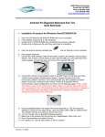
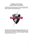
Step 5 Another message will pop up asking you to enter the name of the bike owner. This message will
be displayed every time a new key is programmed.
5
Step 6
At the end of the programming mode, a PASS or FAIL message will be displayed. If the programming is
successful, go to Step 7. If you have an error message, refer to Steps 8 or 9.
6
Step 7
After successfully programming, turn ignition off, wait 10 seconds and turn ignition on again, then run the
bike. Skip to Step 10.
7
Step 8 If during the programming you get the error message shown above, disconnect the ECM/ECU for
30 seconds, then reconnect, then begin programming again. If this message persists, remove all the fuses
and relays from the fuse box of the bike except the ECM/ECU and ignition fuse. Reprogram the ECM/ECU
and put back all the fuses.
8
Step 9 If during the programming you get this error message, disconnect the ECM/ECU for 30 seconds,
then reconnect, then begin programming again. If this message persists, then remove all the fuses and
relays from the fuse box of the bike except the ECM/ECU and ignition fuse. Reprogram the ECM/ECU and
put back all the fuses.
9
Step 10 Go to View and select Gages, then go to Communication and select Connect. As you are revving
the bike, the tracer will be moving in the front & rear map. This feature is called tracer and is showing you in
real time your exact map location based on RPM and Throttle Position.
10
Step 11 You can now change a value by double clicking on the cell and then use the + (Rich) and - (Lean)
buttons to modify values, then click Apply.
11
Step 12
use.
After making the changes to the map, go to File and select Save As and save the file for future
12
4. DIRECT LINK AUTO TUNE FEATURE STEP-BY-STEP GUIDE
Below left: Harley-Davidson serial communication interface box & cable for bikes with DELPHI
ECU/ECM
Below right: close up of Direct-Link A/D (Analog to Digital) wideband O2 sensor inputs cable, as
seen in upper right position of photo at left. Three wires are inside cable: white wire is analog input
1; black wire is analog input 2; shielded wire is ground.
Note: Power supply is not required.
LC-1 Wideband controller
This is one of the products with which Direct Link can interface. The LC-1 is a complete wideband
controller, which uses a Bosch Wideband Sensor from Innovate Motorsports. Other interface
products include the Wego II & III wide-band air/fuel ratio from Daytona Twintec.
13
Step 1
Under Options select External O2 Controller
Step 2
Choose the type of O2 controller. Options for use with the serial cable are the TR-M300, or the LC1 or LM-1, both from Innovate Motorsport. A/D output is available from Wego from Daytona
Twintec.
14
Step 4 If you are using the serial cable (with TR-M300, or the LM-1 or LC-1), you must select the
appropriate COM port for each device. If you are not using the serial cable (i.e. you are using the Wego), you
do not need to select a COM port.
Step 5
Once a map is loaded, select Auto Tune on front and rear cylinder maps.
15
Step 6 Using the mouse, select Options. First select Edit on Tracer and then select Auto Tune
(Start/Stop). You can also select Auto Tune by clicking on the Auto Tune icon located on the tool bar.
16
Step 7
As you move the throttle you will notice that the number in the cells will be changing. The green
color indicates that that cell has been changed and that you can now move to the next cell.
17