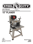
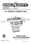
1
® User Manual Read and understand this manual before using machine. 14” HYBRID STYLE BANDSAW Model Number 50150G 50150C STEEL CITY TOOL WORKS VER. 12.19.13 ® l City Bandsaw. ee St w ne ur yo ng si ha rc THANK YOU for pu d inspected with you, an , ed st te , ed gn si de en This bandsaw has be , used and mained bl m se as ly er op pr n he the customer, in mind. W years of trouble free ith w u yo e id ov pr ill w w tained, your bandsa best machinery e th of e on by ed ck ba is service, which is why it ss. warranties in the busine ’s products in the Steel City y an m of e on st ju is w This bandsa t proof of our commitmen is d an ry ne hi ac m ng ki family of woodwor to total customer satisfa ction. cellence each and every ex r fo e riv st to ue in nt At Steel City we co . For comments er om st cu r ou u, yo of n day and value the opinio orks, please visit our web W ol To ity C l ee St or w about your bandsa works.com . site at www.steelcitytool TABLE OF CONTENTS INTRODUCTION Product Specifications ........................................................................................................................................................2 Accessories and Attachments ............................................................................................................................................2 Definition of Terms ..............................................................................................................................................................2 Feature Identification ..........................................................................................................................................................3 General Safety....................................................................................................................................................................4 Product Safety ....................................................................................................................................................................6 Electrical Requirements......................................................................................................................................................7 Grounding Instructions........................................................................................................................................................8 Unpacking & Inventory........................................................................................................................................................9 Assembly ..........................................................................................................................................................................11 Adjustments ......................................................................................................................................................................13 Operations ........................................................................................................................................................................19 Maintenance .....................................................................................................................................................................21 Troubleshooting ................................................................................................................................................................23 INTRODUCTION This user manual is intended for use by anyone working with this machine. It should be kept available for immediate reference so that all operations can be performed with maximum efficiency and safety. Do not attempt to perform maintenance or operate this machine until you have read and understand the information contained in this manual. The drawings, illustrations, photographs, and specifications in this user manual represent your machine at time of print. However, changes may be made to your machine or this manual at any time with no obligation to Steel City Tool Works. 1 PRODUCT SPECIFICATIONS Product Dimensions: Product Specifications: Cutting Capacity (Height) 6” / 152 mm Footprint 31” x 27” Cutting Capacity (Width) 13 1/2” / 330 mm Width 22” / 560 mm Blade Length 93.5” Depth 21” / 540 mm Blade Speed 2500 SFPM Height 65” / 1651 mm Minimum Blade Width 1/8” Net Weight 251 lb. / 114 kg Maximum Blade Width 3/4” Table Size 16” X 16” Table Tilt 45R, 3L Carton Type Cardboard / Metal Table Height from Floor 39” / 1015 mm Width 23” / 580 mm Wheel Diameter 14” / 356 mm Depth 22” / 560 mm Dust Port Size 4” / 102 mm Height 68” / 1727 mm Gross Weight 256 lbs. / 116 kg Shipping Dimensions: Motor Specifications: Horsepower 1 HP Amps 12.5 Volts 115 Phase Single Hertz 60 Hz RPM 1725 ACCESSORIES AND ATTACHMENTS 50400 Height Kit 50405G Fence/Rail Assembly 50411 Premium Bandsaw Blade 93 1/2” x 3/16” x 10T x .025 RK 50415 Premium Bandsaw Blade 93 1/2” x 1/2” x 3T x .032 AS There are a variety of accessories available for your Steel City Product. For more information on any accessories associated with this and other machines, please contact your nearest Steel City distributor, or visit our website at: www.steelcitytoolworks.com DEFINITION OF TERMS Blade drift: A problem that may occur when the blade begins to wander off the cutting line. Ripping: Cutting lengthwise down the workpiece with the grain of the wood. Crosscutting: Cutting across the grain of the workpiece. Set: Refers to the way in which the saw teeth are bent or positioned. Guide Bearings: Located on either side of the blade, providing stability for blade while in operation. Tracking: Refers to the position of the saw blade on the wheels while the machine is running. Resaw: The process of slicing stock to reduce its thickness. Thrust Bearing: Located behind the saw blade, providing support to the back of the blade when the saw is in operation. 2 FEATURE IDENTIFICATION B C A D I E A. Power Switch B. Tension Knob C. Flexible Lamp D. Blade Guard E. Table F. Mobile Base Caster Assembly F 3 GENERAL SAFETY ! WARNING ! WARNING TO AVOID serious injury and damage to the machine, read and follow all Safety and Operating Instructions before assembling and operating this machine. This manual is not totally comprehensive. It does not and can not convey every possible safety and operational problem which may arise while using this machine. The manual will cover many of the basic and specific safety procedures needed in an industrial environment. Exposure to the dust created by power sanding, sawing, grinding, drilling and other construction activities may cause serious and permanent respiratory or other injury, including silicosis (a serious lung disease), cancer, and death. Avoid breathing the dust, and avoid prolonged contact with dust. The dust may contain chemicals known to the State of California to cause cancer, birth defects or other reproductive harm. All federal and state laws and any regulations having jurisdiction covering the safety requirements for use of this machine take precedence over the statements in this manual. Users of this machine must adhere to all such regulations. Some examples of these chemicals are: • Lead from lead-based paints. • Crystalline silica from bricks, cement and other masonry products. • Arsenic and chromium from chemically-treated lumber. Below is a list of symbols that are used to attract your attention to possible dangerous conditions. ! This is the international safety alert symbol. It is used to alert you to potential personal injury hazards. Obey all safety messages that follow this symbol to avoid possible injury or death. ! Always operate tool in well ventilated area and provide for proper dust removal. Use a dust collection system along with an air filtration system whenever possible. Always use properly fitting NIOSH/OSHA approved respiratory protection appropriate for the dust exposure, and wash exposed areas with soap and water. DANGER Indicates an imminently hazardous situation which, if not avoided, WILL result in death or serious injury. ! 1. To avoid serious injury and damage to the machine, read the entire User Manual before assembly and operation of this machine. WARNING Indicates a potentially hazardous situation which, if not avoided, COULD result in death or serious injury. ! CAUTION ! WARNING Indicates a potentially hazardous situation, if not avoided, MAY result in minor or moderate injury. It may also be used to alert against unsafe practices. CAUTION 2. ALWAYS wear eye protection. Any machine can throw debris into the eyes during operations, which could cause severe and permanent eye damage. Everyday eyeglasses are NOT safety glasses. ALWAYS wear Safety Goggles (that comply with ANSI standard Z87.1) when operating power tools. CAUTION used without the safety alert symbol indicates a potentially hazardous situation which, if not avoided, may result in property damage. NOTICE This symbol is used to alert the user to useful information about proper operation of the machine. ! 11. DO NOT FORCE the machine to perform an operation for which it was not designed. It will do a safer and higher quality job by only performing operations for which the machine was intended. WARNING 12. DO NOT stand on a machine. Serious injury could result if it tips over or you accidentally contact any moving part. 3. ALWAYS wear hearing protection. Plain cotton is not an acceptable protective device. Hearing equipment should comply with ANSI S3.19 Standards. ! 13. DO NOT store anything above or near the machine. 14. DO NOT operate any machine or tool if under the influence of drugs, alcohol, or medication. WARNING 15. EACH AND EVERY time, check for damaged parts prior to using any machine. Carefully check all guards to see that they operate properly, are not damaged, and perform their intended functions. Check for alignment, binding or breakage of all moving parts. Any guard or other part that is damaged should be immediately repaired or replaced. 4. ALWAYS wear a NIOSH/OSHA approved dust mask to prevent inhaling dangerous dust or airborne particles. 16. Ground all machines. If any machine is supplied with a 3-prong plug, it must be plugged into a 3-contact electrical receptacle. The third prong is used to ground the tool and provide protection against accidental electric shock. DO NOT remove the third prong. 5. ALWAYS keep the work area clean, well lit, and organized. DO NOT work in an area that has slippery floor surfaces from debris, grease, and wax. 6. ALWAYS unplug the machine from the electrical receptacle before making adjustments, changing parts or performing any maintenance. 17. Keep visitors and children away from any machine. DO NOT permit people to be in the immediate work area, especially when the machine is operating. 7. AVOID ACCIDENTAL STARTING. Make sure that the power switch is in the “OFF” position before plugging in the power cord to the electrical receptacle. ! 18. KEEP protective guards in place and in working order. 19. MAINTAIN your balance. DO NOT extend yourself over the tool. Wear oil resistant rubber soled shoes. Keep floor clear of debris, grease, and wax. WARNING 20. MAINTAIN all machines with care. ALWAYS KEEP machine clean and in good working order. KEEP all blades and tool bits sharp. 21. NEVER leave a machine running, unattended. Turn the power switch to the OFF position. DO NOT leave the machine until it has come to a complete stop. 8. AVOID a dangerous working environment. DO NOT use electrical tools in a damp environment or expose them to rain or moisture. ! 22. REMOVE ALL MAINTENANCE TOOLS from the immediate area prior to turning the machine ON. WARNING 23. SECURE all work. When it is possible, use clamps or jigs to secure the workpiece. This is safer than attempting to hold the workpiece with your hands. 24. STAY ALERT, watch what you are doing, and use common sense when operating any machine. DO NOT operate any machine tool while tired or under the influence of drugs, alcohol, or medication. A moment of inattention while operating power tools may result in serious personal injury. 9. CHILDPROOF THE WORKSHOP AREA by removing switch keys, unplugging tools from the electrical receptacles, and using padlocks. 10. DO NOT use electrical tools in the presence of flammable liquids or gasses. 25. USE ONLY recommended accessories. Use of incorrect or improper accessories could cause serious injury to the operator and cause damage to the machine. If in doubt, DO NOT use it. 28. SAVE these instructions and refer to them frequently and use them to instruct other users. 29. Information regarding the safe and proper operation of this tool is also available from the following sources: 26. THE USE of extension cords is not recommended for 230V equipment. It is better to arrange the placement of your equipment and the installed wiring to eliminate the need for an extension cord. If an extension cord is necessary, refer to the chart in the Grounding Instructions section to determine the minimum gauge for the extension cord. The extension cord must also contain a ground wire and plug pin. Power Tool Institute 1300 Summer Avenue Cleveland, OH 44115-2851 www.powertoolinstitute.org National Safety Council 1121 Spring Lake Drive Itasca, IL 60143-3201 27. Wear proper clothing, DO NOT wear loose clothing, gloves, neckties, or jewelry. These items can get caught in the machine during operations and pull the operator into the moving parts. Users must wear a protective cover on their hair, if the hair is long, to prevent it from contacting any moving parts. American National Standards Institute 25West 43rd. St, 4th Floor New York, NY. 10036 ANSI 01.1 Safety Requirements For Woodworking Machines WWW.ANSI.ORG U.S. Department of Labor Regulations OSHA 1910.213 Regulations WWW.OSHA.GOV PRODUCT SAFETY 1. Serious personal injury may occur if normal safety precautions are overlooked or ignored. Accidents are frequently caused by lack of familiarity or failure to pay attention. Obtain advice from supervisor, instructor, or another qualified individual who is familiar with this machine and its operations. 5. STOP using this machine, if at any time you experience difficulties in performing any operation. Contact your supervisor, instructor or machine service center immediately. 6. Safety decals are on this machine to warn and direct you to how to protect yourself or visitors from personal injury. These decals MUST be maintained so that they are legible. REPLACE decals that are not legible. 2. Every work area is different. Always consider safety first, as it applies to your work area. Use this machine with respect and caution. Failure to do so could result in serious personal injury and damage to the machine. 7. DO NOT leave the unit plugged into the electrical outlet. Unplug the unit from the outlet when not in use and before servicing, performing maintenance tasks, or cleaning. 3. Prevent electrical shock. Follow all electrical and safety codes, including the National Electrical Code (NEC) and the Occupational Safety and Health Regulations (OSHA). All electrical connections and wiring should be made by qualified personnel only. ! 8. ALWAYS turn the power switch “OFF” before unplugging the bandsaw. ! WARNING WARNING 9. DO NOT handle the plug or bandsaw with wet hands. 4. TO REDUCE the risk of electrical shock. DO NOT use this machine outdoors. DO NOT expose to rain or moisture. Store indoors in a dry area. 10. USE accessories only recommended by Steel City. 19. ADJUST all blade guides as specifided in the operating instructions. 11. DO NOT pull the bandsaw by the power cord. NEVER allow the power cord to come in contact with sharp edges, hot surfaces, oil or grease. 20. ADJUST the upper guide to a point about 1/4” above the workpiece being cut. 12. DO NOT unplug the bandsaw by pulling on the power cord. ALWAYS grasp the plug, not the cord. 21. DO NOT cut workpieces that do not have a flat bottom without properly supporting the piece to maintain a stable position. 13. REPLACE a damaged cord immediately. DO NOT use a damaged cord or plug. DO NOT USE if the bandsaw is not operating properly, or has been damaged, left outdoors or has been in contact with water. 22. KEEP hand and fingers away from blade. 23. HOLD workpiece firmly and use a moderate feed speed. 14. DO NOT use the bandsaw as a toy. DO NOT use near or around children. 24. MAKE “relief” cuts before cutting curves. 15. ENSURE that the machine sits firmly on the floor before using. If the machine wobbles or is unstable, correct the problem by using shims or blocks prior to operation. 25. TURN OFF machine before backing the workpiece out of an incomplete cut. 26. TURN OFF the machine before removing scrap pieces. 16. MATCH the blade type and size to the workpiece being cut. 27. With the machine TURNED OFF, clean dust build-up around lower blade guides regularly. 17. MAKE SURE that the blade tension is set appropriately for the size of blade being used. 18. MAKE SURE that the blade is tracking properly by manually turning the wheels before starting the machine. ELECTRICAL REQUIREMENTS ! The switch provided with your saw is designed to function at 115 volts. The switch and saw come prewired for 115 volt operation. WARNING To reduce the risk of electric shock, follow all electrical and safety codes, including the National Electric Code (NEC) and the Occupational Safety and Health Regulations (OSHA). All electrical connections and wiring should be made by qualified personnel only. 7 GROUNDING INSTRUCTIONS ! EXTENSION CORDS WARNING ! WARNING This machine MUST BE GROUNDED while in use to protect the operator from electric shock. To reduce the risk of fire or electrical shock, use the proper gauge of extension cord. When using an extension cord, be sure to use one heavy enough to carry the current your machine will draw. In the event of a malfunction or breakdown, GROUNDING provides the path of least resistance for electric current and reduces the risk of electric shock. The plug MUST be plugged into a matching electrical receptacle that is properly installed and grounded in accordance with ALL local codes and ordinances. The smaller the gauge-number, the larger the diameter of the extension cord is. If in doubt of the proper size of an extension cord, use a shorter and thicker cord. An undersized cord will cause a drop in line voltage resulting in a loss of power and overheating. If a plug is provided with your machine DO NOT modify the plug. If it will not fit your electrical receptacle, have a qualified electrician install the proper connections to meet all electrical codes local and state. All connections must also adhere to all of OSHA mandates. ! IMPROPER ELECTRICAL CONNECTION of the equipment-grounding conductor can result in risk of electric shock. The conductor with the green insulation (with or without yellow stripes) is the equipment-grounding conductor. DO NOT connect the equipment-grounding conductor to a live terminal. USE ONLY a 3-wire extension cord that has a 3-prong grounding plug and a 3-pole receptacle that accepts the machine’s plug. If you are using an extension cord outdoors, be sure it is marked with the suffix “W-A” (“W” in Canada) to indicate that it is acceptable for outdoor use. Check with a qualified electrician or service personnel if you do not completely understand the grounding instructions, or if you are not sure the tool is properly grounded. Make certain the extension cord is properly sized, and in good electrical condition. Always replace a worn or damaged extension cord immediately or have it repaired by a qualified person before using it. Protect your extension cords from sharp objects, excessive heat, and damp or wet areas. PLUGS/RECEPTACLES ! CAUTION WARNING MINIMUM RECOMMENDED GAUGE FOR EXTENSION CORDS (AWG) 115 VOLT OPERATION ONLY Electrocution or fire could result if this machine is not grounded properly or if the electrical configuration does not comply with local and state electrical codes. 0 to 6 Amps 6 to 10 Amps 10 to 12 Amps 12 to 15 Amps MAKE CERTAIN the machine is disconnected from power source before starting any electrical work. MAKE SURE the circuit breaker does not exceed the rating of the plug and receptacle. The motor supplied with your machine is a 115 volt, 60 hertz, single phase motor. The machine should only be connected to an outlet having the same configuration as the plug. 8 25’ LONG 50’ LONG 100’ LONG 18 AWG 18 AWG 16 AWG 14 AWG 16 AWG 16 AWG 16 AWG 12 AWG 16 AWG 14 AWG 14 AWG Not recommended UNPACKING & INVENTORY ! Remove any protective materials and coatings from all of the parts and the bandsaw. After cleaning, apply a good quality paste wax to any unpainted surfaces. Make sure to buff out the wax before assembly. WARNING Compare the items to inventory figures; verify that all items are accounted for before discarding the shipping box. The machine is heavy, two people are required to unpack and lift. Use a safety strap to avoid tip over when lifting machine. ! If any parts are missing, do not attempt to plug in the power cord and turn “ON” the machine. The machine should only be turned “ON” after all the parts have been obtained and installed correctly. For missing parts, contact Steel City at 1-877-SC4-TOOL. Check shipping carton and machine for damage before unpackaging. Carefully remove packaging materials, parts and machine from shipping carton. Always check for and remove protective shipping materials around motors and moving parts. Lay out all parts on a clean work surface. SAW BODY ASSEMBLY A. Assembly NOTE: Your new SCTW Band Saw is over 90% assembled. WARNING A 9 CIRCLE CUTTER A. Pin B. Allen 5mm C. Sliding Rod D. Thumb Screw E. Lock Knob F. Base G. Block B A D F C E G TABLE A. Table B. Knobs (2) C. Insert D. Trunnion (2) E. Mounting Inserts F. Taper Pin (cast only) D B A C F E MOBILITY KIT A. Adjustable Feet (2) B. Flip Wheel Assembly C. Allen Keys 3mm, 5mm (2) D. Carriage Bolts (2) E. Nuts (2) A B D 10 E C ASSEMBLY ATTACHING MOBILE BASE ! WARNING MAKE CERTAIN THAT THE SAW IS DISCONNECTED FROM THE POWER SOURCE. The mobile base consists of one rotating adjustable caster wheel and two stationary wheels that allows you to move the bandsaw around your shop with ease. To install: 1. Remove the 3 mounting bolts that hold the bandsaw to the metal pallet. Lay the cardboard carton on the floor in a flat position. With assitance, tip the bandsaw onto the cardboard with the spine side down. SEE FIG.1 . 2. The stationary wheels have already been attached (A). Check to see that the bolts are tight in case they came loose in transport. SEE FIG.1 . 3. Fasten the caster wheel assembly (FIG.1 (B)) to the base using the two carriage bolts and nuts (see mobility kit parts list on page 10). 4. Attach the leveling feet (C) by screwing the studs into the threaded holes from the bottom of the base. Do not tighten nuts (D) at this time as the feet will need to be adjusted to match the location of the bandsaw. SEE FIG.2 . B C D A FIG.1 FIG.2 11 MOUNTING THE TABLE ! WARNING MAKE CERTAIN THAT THE SAW IS DISCONNECTED FROM THE POWER SOURCE. 1. Raise the guard all the way to the highest position and leave the blade under tension. FIG.3 (A) shown in shipping position. D 2. With the bolts hanging free (FIG.4 (B)), guide the blade through the slot in the table (FIG.5 (C)) and turn the table to guide the bolts into the openings in the trunnion bracket (FIG.6 (D)). 3. With bolts in place, turn knob (E) clockwise to tighten and repeat for the other side. SEE FIG.7 . FIG.6 4. Install the red insert into the opening (F) with detent in the slot. Please take note that the insert can go in upside down from reverse, this is your choice. SEE FIG.8 . 5. Completed assembly. SEE FIG.9 . E A FIG.7 FIG.3 F FIG.8 B FIG.4 C FIG.5 FIG.9 12 ADJUSTMENTS TABLE TILT The table on your bandsaw is designed to tilt up to 45 degrees to the right and up to 3 degrees to the left. To tilt the table: 1. Loosen both lock knobs (A) on the underside of the table. SEE FIG.15 (only one knob shown). 2. Tilt the table to the right noting that the scale (B) shows the angle of the table. 3. Retighten lock knobs when desired angle is achieved. 4. In order to tilt the table to the left and/or set the table at 90 degrees, you will need to adjust the stopping bolt under the table (A). To set the stop for the right tilting of the table, adjust (B). SEE FIG.16 5. B A FIG.17 shows square on table and against saw blade (C). B FIG.15 A C FIG.16 FIG.17 13 SETTING BLADE TENSION BLADE TRACKING The blade tension is set by using the blade tension knob. It MUST be set prior to initial operation as it plays a vital role in setup of other features of the bandsaw. It should also be checked when the blade is replaced, and from time to time as the blade will stretch after prolonged use. Keep in mind that putting too much or too little tension can cause either blade breakage (too much pressure) or poor cutting results (too little pressure). Blade tracking refers to the way the saw blade rides on the wheels while the machine is in operation. This adjustment has been set at the factory, but it is a good practice to check the tracking each time before using the machine. Tracking should also be checked after a blade change. ! ! WARNING MAKE CERTAIN THAT THE SAW IS DISCONNECTED FROM THE POWER SOURCE. WARNING MAKE CERTAIN THAT THE SAW IS DISCONNECTED FROM THE POWER SOURCE. 1. Loosen the tension on the blade by rotating knob counter clockwise. SEE FIG.18 (B) . 2. Set the blade tension by rotating the knob (B) Turning the knob clockwise increases the tension while turning the knob counterclockwise decreases the tension. 3. As you rotate the knob you will notice a red marker (C) on the inside of the scale. This is to be used as a guideline for the blade tension depending on the width of the blade. For example, if you are using a 1/8” blade, align the red marker inside the scale with the 1/8” mark on the outside of the scale. SEE FIG.19 . 1. Open the upper door exposing the top wheel of the bandsaw. 2. Rotate the wheel clockwise, by hand, and take note of the position of the blade on the wheel. The blade should ride on the center of the wheel. 3. If the blade does not ride on the center of the wheel, or starts to move towards the edge of the wheel, loosen the wingnut (A) and turn the tracking adjustment knob (B). SEE FIG.19 . NOTICE: When using the tracking adjustment knob, do so in small increments as this is a sensitive adjustment. NOTE: The scale is only recommended guideline for tensioning. Always follow the blade manufacturer’s recommendations for proper blade tension. 4. Rotate the wheel again. Repeat steps 2 through 4 until the blade rides on the center of the wheel. 5. Once proper tracking is achieved, close and secure the upper door and retighten wing nut loosened in step 3. NOTE: When the bandsaw is not in use, it is a good idea to release the tension on the blade using the knob (B) . B A C B FIG.18 FIG.19 14 ADJUSTING TABLE POSITIVE STOPS ! CAUTION DO NOT attempt to set the positive stops until you have checked and/or adjusted both the blade tension and blade tracking. Refer to SETTING BLADE TENSION and BLADE TRACKING in the ADJUSTMENTS section of this manual. SETTING 90 DEGREE STOP 1. Loosen both locking knobs (A). SEE FIG.20 (only one shown). 2. Let table rest on 90 degree stop (B). SEE FIG.21 . 3. Place square on table top and up against the saw blade (C). SEE FIG.22 . If an adjustment is necessary, tilt the table until it is square to the blade and tighten the two lock knobs (A). SEE FIG.20 . 4. Loosen hex nut (D) and adjust the 90 degree positive stop bolt (E) until it contacts the underside of the table. Retighten the nut (D). SEE FIG.21 . 5. Adjust the pointer on the bevel scale (F). SEE FIG.20 (shown off mark for your reference). SETTING 45 DEGREE STOP 1. Loosen both locking knobs (A). SEE FIG.20 (only one shown). 2. Tilt the table until the pointer reaches the 45 degree mark on the scale (I). SEE FIG.20 . 3. If an adjustment is necessary, loosen hex nut (G), adjust 45 degree stop bolt (H) until the contacts the table and then tighten (G). To make adjustment, use Allen Key 3mm from bottom side (arrow). Turn right or left to achieve 45 degrees, then tighten (G). SEE FIG.21 . B E H D I G F A FIG.20 C FIG.22 15 FIG.21 UPPER BEARING ADJUSTMENT LOWER BEARING ADJUSTMENT NOTICE: Make certain that you have followed all of the steps in the SETTING BLADE TENSION section in the adjustments section of this manual prior to starting this section. ! ! MAKE CERTAIN THAT THE SAW IS DISCONNECTED FROM THE POWER SOURCE. WARNING 1. Loosen thumbscrew (G) and slide the thrust bearing (K) until it is within .003 (arrow) of the saw blade. Equivalent to thickness of a buisness card. Once set, tighten the thumbscrew. SEE FIG.24 . 2. The guide bearings (H) should be positioned within 1/32” of the blade. If an adjustment is necessary, loosen thumb knob (I) and adjust knob (J), only one shown, until the bearing is positioned the correct distance away and behind the teeth, taking into account the thrust bearing settings. Repeat for both left and right sides. Tighten the thumb knob (I) at this time. SEE FIG.24 . 3. Spin the wheels by hand to see if more adjustments are needed. MAKE CERTAIN THAT THE SAW IS DISCONNECTED FROM THE POWER SOURCE. 1. Remove the guard by loosening the 2 Philipps screws (A). SEE FIG.23 (screw driver not supplied). 2. Loosen thumbscrew (B) for the thrust bearing (C) and slide until it is within .003 (arrow) of the saw blade. Equivalent to thickness of a buiness card. Once bearing is set, tighten the thumbscrew (B). SEE FIG.24 . 3. The guide bearings (D) should be positioned within 1/32” of the blade. If an adjustment is necessary, loosen thumbscrew (E) and adjust knob (F), only one shown, until the bearing is positioned the correct distance away and behind the teeth, taking into account the thrust bearing settings. Repeat for both left and right sides. Tighten the thumbscrews at this time. SEE FIG.24 . 4. WARNING Note: The table was removed for clarification. C B Spin the wheels by hand to see if more adjustments are needed. D F E G K A J H I FIG.23 FIG.24 16 CIRCLE CUTTING ATTACHMENT A. Drawing Pin B. Hex Wrench 5 mm FIG.25 B A C C. Thumb Screw D. Slide Rod E. Allen Screw F. D Slide Block G E G. Slide Base F H H. Knob INSTALLING CIRCLE CUTTING ATTACHMENT 1. Layout the parts on the table for easy access. SEE FIG.26 (refer and match parts from FIG.25) . 2. Place the slide base (G) around the elevation rod (X) and position the slide block (F) into position to drop into place. SEE FIG.27 . 3. With the slide block in position (F), tighten the Allen screw (E) with the hex wrench (B). SEE FIG.27 . 4. Slide the rod (D) into position through the slide base (G) by loosening the knob (H) and then tighten knob. SEE FIG.28 . 5. Loosen the thumbscrew (C) and slide the drawing pin (A) through the rod (D). SEE FIG.29 . 6. Finished assembly SEE FIG.30 . To use this attachment, place your stock on the table. With the center marked on the wood, position the drawing pin over the cross by loosening the knob and the thumbscrew. Tighten the knob and use a mallet to tap the top of the drawing pin to seat in the X cross on the wood and tighten thumbscrew. Next, turn on the bandsaw and begin to push stock through the blade to cut. For a live demonstration, check out on YouTube. X F G B E G B D H E F A FIG.26 FIG.27 FIG.30 G A D D C H FIG.28 17 FIG.29 BELT TENSION The belt tension is adjusted by moving the motor. SEE FIG.31 . 1. Loosen 4 carriage bolts and nuts ((A) two shown). Slide the motor lower in the slots (B) until desired tension is achieved. SEE FIG.31 . Approximately 1/2” of deflection at the midpoint. SEE FIG.32 (C) . Belt tension should be done at the beginning of use and checked periodically as the belt may stretch over time. A B C FIG.32 FIG.31 18 OPERATIONS ! WARNING ALWAYS wear a NIOSH/OSHA approved dust mask to prevent inhaling dangerous dust or airborne particles. ALWAYS wear eye protection. Any machine can throw debris into the eyes during operations, which could cause severe and permanent eye damage. Everyday eyeglasses are NOT safety glasses. ALWAYS wear Safety Goggles (that comply with ANSI standard Z87.1) when operating power tools. ! WARNING ! NOTICE: The following section was designed to give instructions on the basic operations of this bandsaw. However, it is in no way comprehensive of every bandsaw application. It is strongly recommended that you read books, trade magazines, or get formal training to maximize the potential of your bandsaw and to minimize the risks. WARNING MAKE CERTAIN THAT THE SAW IS DISCONNECTED FROM THE POWER SOURCE. PRE RUN CHECK G Before you begin using your new bandsaw, you should give it a thorough inspection and ask yourself the following questions: 1. Are the guide bearings above and below the table adjusted properly? 2. Is the blade tension and tracking properly set? 3. Is the unit stable? Does it rock or wobble? Are the feet adjusted? 4. Have you read all the warning associated with this bandsaw? F FIG.33 BLADE GUARD HEIGHT 1. 2. The red guard height is set by loosening the thumbscrew (A) and by using hand to raise and lower. The guard should be no higher than 1/4” above the workpiece during use. SEE FIG.34 . E A To fine tune the guard to enter the upper wheel guard housing, you may loosen the set screw (C) on the bearing assembly and elevation shaft (D). Shift and then tighten as needed. SEE FIG.34 . 3. If there is sloppiness in the elevation movement, you can adjust the set screw (E) located just below the thumbscrew. This meets with the slot in the elevation shaft. SEE FIG. 34 . 4. To adjust vertical, loosen the 2 Philipps screws (F) with driver (not supplied) shift the guard (G) and then tighten both screws. SEE FIG.33 . G D C F FIG.34 19 BLADE SELECTION PITCH Using the proper saw blade for the job you are performing will optimize the efficiency of your bandsaw and increase the quality of your work. There are some basic questions that apply when determining which type of blade to use. The unit of measure for pitch is teeth per inch. A fine pitch, meaning having more teeth per inch, will deliver a smoother cut, but will take a longer time to complete. A coarse pitch, meaning having fewer teeth per inch, will cut much faster, but leave a rougher finish. A good rule of thumb is the thicker the workpiece, the coarser the pitch should be. What type of material is to be cut? How thick is the workpiece? TOOTH SHAPE What features does the workpiece contain, i.e. bends, curves, etc.? Tooth shapes come in several basic types. Three of them are hook, skip, and variable. Skip and hook types are used to help obtain a higher feed rate when cutting thick workpieces, while variable combines the features of two types of blades. These questions will help you with determining which type of blade to use. The type of blade is determined by 5 features. They are: 1. Blade width 2. Pitch SET 3. Tooth shape 5. Blade material The term “set” refers to the way that the saw teeth are bent or positioned. Set patterns are selected depending on the type of material being cut. BLADE WIDTH BLADE MATERIAL Blades for the bandsaw are available in different standard widths. This width is measured from the rear of the blade to the tip of the tooth. In general, a wider blade is used for ripping and generally straight line cuts. The narrower blades are mainly used for cutting a workpiece with curves and bends. Bandsaw blades can be made from different types of materials. Some common materials are carbon steel, spring steel, and high speed steel. 4. Set BLADE DRIFT Blade drift occurs when the blade begins to wander off the cutting line. It can be caused by several factors. Incorrect Blade Tension Wrong Blade Type Dull Blade If you experience blade drift, check the appropriate adjustments first. If this does not correct the problem, the blade may have to be replaced. See BLADE REPLACEMENT in the MAINTENANCE section of this manual for more information. 20 MAINTENANCE GENERAL CLEANUP A. Keep the bearing guides clean and free of buildup of pitch, resin, etc. B. Remove any deposits from the wheels to help avoid vibration and premature blade breakage. C. Keep the inside of the bandsaw clear of sawdust. Occasionally vacuum out the inside of the unit or blow out the inside of the unit with air. D. Clean and grease the raising/lowering mechanism if the unit becomes difficult to move. SEE FIG.35 (A) and (arrows) . INSTALLING / CHANGING BLADES ! WARNING MAKE CERTAIN THAT THE SAW IS DISCONNECTED FROM THE POWER SOURCE. A. Remove the table insert (SEE FIG.36A) and take the tension off of the blade by rotating the knob (B) counter clockwise. SEE FIG.36 . B. Open both upper and lower doors of the bandsaw. C. Carefully remove the blade from between the upper and lower guides and remove the blade from bottom of the wheels. Slide the blade through the slot in the table to remove the old blade. D. To install, reverse the procedure. Guide the new blade through the slot in the table and place onto the center of the upper and lower wheels with the blade passing through the upper and lower bearings. Bearings may need to be reset if you change the size of the blade. E. Replace the table insert. SEE FIG.36A . NOTE: The teeth of the blade must point down and towards the front of the saw. B A FIG.35 FIG.36 21 FIG.36A REPLACING POLY-V BELT ! WARNING MAKE CERTAIN THAT THE SAW IS DISCONNECTED FROM THE POWER SOURCE. 1. Open the lower door by rotating the black knob counter clockwise (A). SEE FIG.37 . 2. Remove the 3 screws on the right side (B) and repeat on the left side with a Philipp’s driver (not supplied). SEE FIG.37 . 3. Release blade tension. Refer to instructions for CHANGING THE BLADE. Remove the blade. 4. With the belt exposed, loosen motor mount carraige bolts and slide motor in to the slots. SEE FIG.39 (B) . 5. Remove belt from upper pulley (H) and lower pulley (F). FIG.38 . 6. Remove belt by bringing up through the opening and move over the wheel starting on the left side and under the wheel and off the right side. 7. To replace, reverse the process. SEE FIG.38 . 8. Reattached the lower panel and replace the 6 Philipps screws that were removed. Install the blade and apply proper tension and tracking. Close the door and lock by clockwise turning the black knob. Slide motor into position and tighten bolts and nuts. SEE FIG.39 (B) . NOTICE: Before operating bandsaw, make sure to go back to the ADJUSTMENTS section of this manual and redo the following sections: Setting Blade Tension Blade Tracking Upper and Lower Guide Bearing Adjustments H B A F B FIG.37 FIG.38 22 FIG.39 TROUBLESHOOTING GUIDE This section covers the most common processing problems encountered in sawing and what to do about them. Do not make any adjustments until the bandsaw is unplugged and moving parts have come to a complete stop. PROBLEM LIKELY CAUSE(S) SOLUTION Saw stops or will not start. 1. Saw unplugged. 1. Check plug connections. 2. Fuse blown, or circuit breaker tripped. 2. Replace fuse, or reset circuit breaker. 3. Cord damaged. 3. Replace cord. 1. Stop not adjusted correctly. 1. Check blade with square and adjust stop. 2. Angle pointer not set accurately. 2. Check blade with square and adjust pointer. 3. Miter gauge out of adjustment. 3. Adjust miter gauge. 1. Warped wood. 1. Select another piece of wood. 2. Excessive feed rate. 2. Reduce feed rate. 3. Incorrect blade for cut. 3. Change blade to correct type. 4. Blade tension not set properly. 4. Set blade tension according to blade manufacturer’s specs. 5. Guide bearings not set properly. 5. Review guide bearing adjustment. 1. Dull blade. 1. Replace blade. 2. Blade mounted wrong. 2. Teeth should point down. 3. Gum or pitch on blade. 3. Remove blade and clean. 4. Incorrect blade for cut. 4. Change blade to correct type. 5. Gum or pitch on table. 5. Clean table. 1. Extension cord too light or too long. 1. Replace with adequate size and length cord. 2. Low shop voltage. 2. Contact your local electric company. 1. Base on uneven floor. 1. Reposition on flat, level surface. 2. Bad Poly V-belt. 2. Replace v-belt. 3. Motor mount is loose. 3. Tighten motor mount hardware. 4. Loose hardware. 4. Tighten hardware. Does not make accurate 45° or 90° cuts. Blade wanders during cut. Saw makes unsatisfactory cuts. Blade does not come up to speed. Saw vibrates excessively. 23 DATE MAINTENANCE PERFORMED REPLACEMENT COMPONENTS REQUIRED ® STEEL CITY TOOL WORKS www.steelcitytoolworks.com 1-877-SC4-TOOL (1-877-724-8665) NOTES www.steelcitytoolworks.com Steel City Tool Works, LLC Bolingbrook, IL. USA 60440 Tech Service: 1.877.724.8665