1
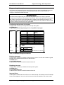
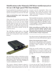
PCI 800 Series
PCI PnP Digital I/O Boards
User’s Manual for
PCI836A/C PCI848A/C PCI896A/C PCI8192A/C
Eagle Technology – Cape Town, South Africa
Copyright © 2001
www.eagle.co.za
PCI 800 Series User Manual
Eagle Technology - Data Acquisition
Digital I/O and Counter Boards
Data Acquisition and Process Control
© Eagle Technology
31-35 Hout Street • Cape Town • South Africa
Phone +27 21 423 4943 • Fax +27 21 424 4637
Email [email protected]
Eagle Technology © Copyright 2001 – www.eagle.co.za
i
PCI 800 Series User Manual
Eagle Technology - Data Acquisition
Copyright
All rights reserved. No part of this publication may be reproduced, stored in a retrieval system,
or transmitted, in any form or any means, electronic, mechanical, by photographing,
recording, or otherwise without prior written permission.
Copyright © Eagle Technology, South Africa
January 2002
Revision 1.3
Information furnished in this manual is believed to be accurate and reliable; however no
responsibility is assumed for its use, or any infringements of patents or other rights of third
parties, which may result from its use.
Trademarks and Logos in this manual are the property of their respective owners.
Product Warranty
Eagle Technology, South Africa, warrants its products from defect in material and
workmanship from confirmed date of purchase for a period of one year if the conditions listed
below are met. The product warranty will call the Eagle Technology Data Acquisition Device
short as ETDAQD.
•
•
•
The warranty does not apply to an ETDAQD that has been previously repaired, altered,
extended by any other company or individual outside the premises of Eagle Technology.
That a qualified person configure and install the ETDAQD, and damages caused to a
device during installation shall make the warranty void and null.
The warranty will not apply to conditions where the ETDAQD has been operated in a
manner exceeding its specifications.
Eagle Technology, South Africa, does not take responsibility or liability of consequential
damages, project delays, damaging of equipment or capital loss as a result of its products.
Eagle Technology, South Africa, holds the option and final decision to repair or replace any
ETDAQD. Proof of purchase must be supplied when requesting a repair.
Eagle Technology © Copyright 2001 – www.eagle.co.za
ii
PCI 800 Series User Manual
Eagle Technology - Data Acquisition
TABLE OF CONTENTS
1.
INTRODUCTION
1
Features
1
Applications
1
Key Specifications
1
Software Support
1
Contact Details
1
2.
2
INSTALLATION
Package
2
Operating System Support
2
Hardware Installation
3
Software Installation
Windows 98/2000/ME
Post installation
Windows NT
4
4
6
8
3.
9
INTERCONNECTIONS
External Connector and Accessories
9
Pin Assignments
PCI836A/C – DB37 (M) External
PCI836C – IDC20 (M) - Internal
PCI836C – DB25 (M) – External via Cable
PCI848/896/192 – IDC50 (M) Internal
PCI848/896/8192 C-Version – DB25 (M) - External
Signal Definitions
10
10
10
10
11
11
11
Pin Descriptions
Digital Inputs/Outputs (PA0-7, PB0-7, PC0-7)
External Trigger System (EXT_TRIG, EXT_TRIG_RET)
FREQ_IN and FREQ_OUT
CLK0-2
GATE0-2
OUT0-2
+5V Power Pin (+5V)
+12V Power Pin (+12V)
-12V Power Pin (-12V)
Digital Ground (DGND)
12
12
12
12
12
12
12
12
12
12
12
4.
13
PROGRAMMING GUIDE
EDR Enhanced API
Eagle Technology © Copyright 2001 – www.eagle.co.za
13
iii
PCI 800 Series User Manual
Eagle Technology - Data Acquisition
Digital Inputs/Outputs
Reading the Digital Inputs
Writing to the Digital Outputs
14
14
14
Counters
Writing the initial counter value
Reading the counter value
Configuring a counter
Controlling the counter gate
16
16
17
17
18
Programming Interrupts
Configuring the Interrupt sub-system
Enabling Interrupts
Disabling Interrupts
Interrupt Event
19
19
19
19
19
A.
22
SPECIFICATIONS
Digital Input/Output Characteristics
22
Opto-Isolator (C-Versions)
23
Counter-Timer Characteristics (C-Versions)
23
Bus Interface
23
Power Requirements
23
Dimensions
23
Connectors
24
B.
25
CONFIGURATION CONSTANTS
Query Codes
25
Error Codes
26
Digital I/O Codes
26
C.
27
COUNTER MODES
Mode 0 - Event counter
Gate function
Count value load timing
Count value writing during counting
Count value writing when the gate signal is low
27
27
27
27
27
Mode 1 – Digital one-shot
Gate function
Count value load timing
Count value writing during counting
28
28
28
28
Mode 2 – Rate Generator and Real-Time Clock
Gate function
Count value load timing
Count value writing during counting
28
28
28
28
Eagle Technology © Copyright 2001 – www.eagle.co.za
iv
PCI 800 Series User Manual
Eagle Technology - Data Acquisition
Mode 3 – Square Wave Generator
Gate function
Count value load timing
Count value writing during counting
Even number counting
Odd number counting
29
29
29
29
29
29
Mode 4 – Software Trigger Strobe
Gate function
Count value load timing
Count value writing during counting
30
30
30
30
Mode 5 – Hardware Trigger Strobe
Gate function
Count value load timing
Count value writing during counting
31
31
31
31
D.
LAYOUT DIAGRAM
32
E.
ORDERING INFORMATION
33
Eagle Technology © Copyright 2001 – www.eagle.co.za
v
PCI 800 Series User Manual
Eagle Technology - Data Acquisition
Table of Figures
Figure 4-1 EDR Enhanced Design .................................................................................................... 13
Figure 4-2 Counter-Timer Architecture............................................................................................... 16
Figure C-1 Counter-Timer Mode 0 .................................................................................................... 27
Figure C-2 Counter-Timer Mode 1 .................................................................................................... 28
Figure C-3 Counter-Timer Mode 2 .................................................................................................... 29
Figure C-4 Counter-Timer Mode 3 .................................................................................................... 30
Figure C-5 Counter-Timer Mode 4 .................................................................................................... 30
Figure C-6 Counter-Timer Mode 5 .................................................................................................... 31
Eagle Technology © Copyright 2001 – www.eagle.co.za
vi
PCI 800 Series User Manual
Eagle Technology - Data Acquisition
Table of Tables
Table 1-1 PCI800 Versions ............................................................................................................... 1
Table 2-1 Operating System Support................................................................................................... 2
Table 3-1 PCI800 Connectors............................................................................................................ 9
Table 3-2 PCI836A/C External Connector – DB37 (M) .......................................................................... 10
Table 3-3 PCI836A/C Internal Connector – IDC20 (M) .......................................................................... 10
Table 3-4 PCI836A/C External Connector via Internal Cable– DB25 (M) ................................................... 10
Table 3-5 PCI848/896/8192 IDC50 (M) Connector ............................................................................... 11
Table 3-6 PCI848/896/8192C External Connector – DB25 (M) ................................................................ 11
Table 3-7 Signal definitions ............................................................................................................. 12
Table 4-1 Port Assignments ............................................................................................................ 15
Table 4-2 Counter Assignment......................................................................................................... 16
Table 4-3 Counter Resolution .......................................................................................................... 16
Table 4-4 Counter Resolution .......................................................................................................... 17
Table 4-5 Counter Configuration....................................................................................................... 18
Table 4-6 Gate Configuration........................................................................................................... 18
Table 4-7 EDREIntX.Configure Parameters ........................................................................................ 19
Table 4-8 Event Source.................................................................................................................. 20
Table 4-9 Parameter Setup ............................................................................................................. 21
Table E-1 Ordering Information ........................................................................................................ 33
Eagle Technology © Copyright 2001 – www.eagle.co.za
vii
PCI 800 Series User Manual
Eagle Technology - Data Acquisition
1
1. Introduction
The PCI800 series are 32-bit PCI bus architecture digital input/output and counter-timer data
acquisition boards. They support 36 to 192 digital input/output lines and 3 counters. They
come in 4 basic models, PCI836, PCI848, PCI896 and PCI8192.
Features
The PCI800 series has some very unique features and are listed below:
•
•
•
•
•
•
32-bit PCI bus Revision 2.2 compliant at 33MHz.
PCI Bus 3.3V compatible.
Intel 8255 compatible digital I/O ports.
Intel 8254 compatible counter-timer.
Opto-isolated input.
Programmable interrupts.
Feature
Number of digital channels – A Version
Number of digital channels – C Version
Number of counters – A Version
Number of counters – C Version
Number of 8255 compatible ports (8-bit)
Number of high current ports (16-bit) – C Version
Number of opto-isolated inputs – A Version
Number of opto-isolated inputs – C Version
Number of interrupt sources - A Version
Number of interrupt sources - C Version
PCI 836
24
40
0
0
3
1
0
1
0
3
PCI 848
48
48
0
3
6
0
0
1
0
10
PCI 896
96
96
0
3
12
0
0
1
0
10
PCI 8192
192
192
0
3
24
0
0
1
0
10
Table 1-1 PCI800 Versions
Eagle Technology © Copyright 2001 – www.eagle.co.za
1
PCI 800 Series User Manual
Eagle Technology - Data Acquisition
Applications
The PCI800 series can be used in the following applications:
• Automation test equipment.
• TTL compatible status monitoring.
• Plant/Factory process control.
• Pulse counting.
• Frequency measurement.
• Frequency generation.
• Controlling and monitoring of any TTL compatible equipment.
Key Specifications
•
•
•
•
•
3,6,12 or 24 x 8-bit ports.
3 x 16-bit counters.
Fully programmable digital input/output system.
Fully programmable counter-timer system.
Fully programmable interrupt support.
Software Support
The PCI800 series is supported by EDR Enhanced and comes with an extensive range of
examples. The software will help you to get your hardware going very quickly. It also makes it
easy to develop complicated control applications. All operating system drivers, utility and test
software are supplied on the EDR Enhanced CD-Rom. The latest drivers can also be
downloaded from the Eagle Technology website. For further support information see the
Contact Details section.
Contact Details
Below are the contact details of Eagle Technology.
Eagle Technology
PO Box 4376
Cape Town
8000
South Africa
Telephone +27 (021) 423 4943
Fax +27 (021) 424 4637
E-Mail [email protected]
Website http://www.eagle.co.za
Eagle Technology © Copyright 2001 – www.eagle.co.za
1
PCI 800 Series User Manual
Eagle Technology - Data Acquisition
2
2. Installation
This chapter describes how to install and configure the PCI800 for the first time. Minimal
configuration is necessary; almost all settings are done through software. The PCI BIOS or
operating system will take care of all resource assignments.
Package
PCI800 package will contain the following:
• PCI800 PCI board
• Eagle Technology Software CD-Rom.
Operating System Support
The PCI800 series support the Windows NT and Windows Driver Models (WDM) driver types.
The operating systems are listed in the table below.
Board Type
PCI836A/C
PCI848A/C
PCI896A/C
PCI8192A/C
Revision
Revision 1
Revision 1
Revision 1
Revision 1
Operating Systems
Windows NT/2000/98/ME
Windows NT/2000/98/ME
Windows NT/2000/98/ME
Windows NT/2000/98/ME
Driver Type
NT Sys, WDM PnP
NT Sys, WDM PnP
NT Sys, WDM PnP
NT Sys, WDM PnP
Table 2-1 Operating System Support
Eagle Technology © Copyright 2001 – www.eagle.co.za
2
PCI 800 Series User Manual
Eagle Technology - Data Acquisition
Hardware Installation
This section will describe how to install your PCI board into your computer.
•
Switch off the computer and disconnect from power socket.
Failure to disconnect all power cables
can result in hazardous conditions, as
there may be dangerous voltage levels
present in externally connected
cables.
•
•
•
•
•
•
Remove the cover of the PC.
Choose any open PCI slot and insert PCI board
Insert bracket screw and ensure that the board sits firmly in the PCI socket.
Replace the cover of the PC.
Reconnect all power cables and switch the power on.
The hardware installation is now completed.
Eagle Technology © Copyright 2001 – www.eagle.co.za
3
PCI 800 Series User Manual
Eagle Technology - Data Acquisition
Software Installation
Windows 98/2000/ME
Installing the Windows 98/2000 device driver is a very straightforward task. Because it is plug
and play Windows will auto detect the PCI board as soon as it is installed. No setup is
necessary. You simply have to supply Windows with a device driver.
Wait until Windows detects the new hardware
Select Next
Eagle Technology © Copyright 2001 – www.eagle.co.za
4
PCI 800 Series User Manual
Eagle Technology - Data Acquisition
Select “Search for a suitable driver for my device…” and select next
Make sure only “Specify a location” is selected and select next
Select the browse button and search for the PCI800.inf file on the Eagle CD-Rom.
The driver is normally located in the <CDROM>:\EDRE\DRIVERS\WDM\PCI800
directory.
Eagle Technology © Copyright 2001 – www.eagle.co.za
5
PCI 800 Series User Manual
Eagle Technology - Data Acquisition
Select next when found.
Select next again.
When done you might have to restart your computer.
Post installation
When done with the driver installation the device manager can be open to make sure the
installation was a success.
•
•
First make sure that the driver is working properly by opening the Device Manager.
Check under the Eagle Data Acquisition list if your board is listed and working
properly. See picture below.
Eagle Technology © Copyright 2001 – www.eagle.co.za
6
PCI 800 Series User Manual
•
•
Eagle Technology - Data Acquisition
Clearly you can see that the PCI device is listed and working properly.
Further open the control panel and then the EagleDAQ folder. This dialog should list
all installed hardware. Verify your board’s properties on this dialog. See picture below
Now the first part of your installation has been completed and ready to install the EDR
Enhanced Software Development Kit.
• Run edreapi.exe found on the Eagle CD-Rom and follow the on screen instructions
Eagle Technology © Copyright 2001 – www.eagle.co.za
7
PCI 800 Series User Manual
Eagle Technology - Data Acquisition
Windows NT
The Windows NT driver supports both Windows NT4.0 and Windows 2000. It does not require
any special setup. To install the Windows NT drivers simply run edrewinnt.exe on the Eagle
CD-Rom. This will automatically install the device drivers. Restart your computer when done.
Open the EagleDAQ folder in the control panel to check if your installation was successful.
If you are running on Windows 2000 and it detects a new device simply install a default driver,
or so called placeholder. This will disable the device in the plug and play manager. The NT
driver will take control of the device.
Eagle Technology © Copyright 2001 – www.eagle.co.za
8
PCI 800 Series User Manual
Eagle Technology - Data Acquisition
3
3. Interconnections
The PCI800 series has connectors for digital I/O and counter-timers. The PCI800 range of
boards are compatible with older board like the PC(I)36C and PC192A. The PCI800 boards
make use of DB37, IDC20, IDC50 and DB25 connectors. The PCI836 is compatible with the
older PC36B/C and PCI36C. The PCI848, PC896 and PC8192 are compatible with digital I/O
connectors of the PC192A and the counter-timer connector on the PC14B.
External Connector and Accessories
Depending on the version of PCI800 board, different connectors are fitted of which some are
the same. Use the table below as reference for each type of board.
Board Type
PCI836A
PCI836C
PCI848A
PCI848C
PCI896A
PCI896C
PCI8192A
PCI8192C
DB37(M)
External
1
1
0
0
0
0
0
0
IDC20
Internal
0
1
0
0
0
0
0
0
IDC50
Internal
0
0
2
2
4
4
8
8
DB25(M)
External
0
0
0
1
0
1
1
0
Table 3-1 PCI800 Connectors
Eagle Technology © Copyright 2001 – www.eagle.co.za
9
PCI 800 Series User Manual
Eagle Technology - Data Acquisition
Pin Assignments
PCI836A/C – DB37 (M) External
The table below shows the pin assignments for the DB37(M) connector found on the PCI836A
and C. This is also compatible with the ISA PC36C and PCI36C.
Pin
1
2
3
4
5
6
7
8
9
10
11
12
13
14
15
16
17
18
19
Name
+12V_FUSED
+5V_FUSED
DGND
PA0
PA1
PA2
PA3
PA4
PA5
PA6
PA7
PB0
PB1
PB2
PB3
PB4
PB5
PB6
PB7
Pin
20
21
22
23
24
25
26
27
28
29
30
31
32
33
34
35
36
37
Name
PC3
PC2
PC1
PC0
PC4
PC5
PC6
PC7
DGND
DGND
DGND
DGND
DGND
EXT_TRIG
EXT_TRIG_RET
-12V_FUSED
NC
DGND
Table 3-2 PCI836A/C External Connector – DB37 (M)
PCI836C – IDC20 (M) - Internal
The table below shows the pin assignments for the IDC20 (M) connector found on the
PCI836C. This is also compatible with the PCI36C.
Pin
1
3
5
7
9
11
13
15
17
19
Name
DO0
DO2
DO4
DO6
DO8
DO10
DO12
DO14
DGND
+5V_FUSED
Pin
2
4
6
8
10
12
14
16
18
20
Name
DO1
DO3
DO5
DO7
DO9
DO11
DO13
DO15
DGND
+5V_FUSED
Table 3-3 PCI836A/C Internal Connector – IDC20 (M)
PCI836C – DB25 (M) – External via Cable
The table below shows the pin assignments for the DB25 (M) connector found on the
PCI836C internal ribbon cable
Pin
1
2
3
4
5
6
7
8
9
10
11
12
13
Name
DO0
DO2
DO4
DO6
DO8
DO10
DO12
DO14
DGND
+5V_FUSED
NC
NC
NC
Pin
14
15
16
17
18
19
20
21
22
23
24
25
Name
DO1
DO3
DO5
DO7
DO9
DO11
DO13
DO15
DGND
+5V_FUSED
NC
NC
Table 3-4 PCI836A/C External Connector via Internal Cable– DB25 (M)
Eagle Technology © Copyright 2001 – www.eagle.co.za
10
PCI 800 Series User Manual
Eagle Technology - Data Acquisition
PCI848/896/192 – IDC50 (M) Internal
The table below shows the pin assignments for the IDC(M) connector found on the
PCI848/896/9192A and C. This is also compatible with the ISA PC192A.
Pin
1
3
5
7
9
11
13
15
17
19
21
23
25
27
29
31
33
35
37
39
41
43
45
47
49
Name
PC7
PC6
PC5
PC4
PC3
PC2
PC1
PC0
PB7
PB6
PB5
PB4
PB3
PB2
PB1
PB0
PA7
PA6
PA5
PA4
PA3
PA2
PA1
PA0
+5V_FUSED
Pin
2
4
6
8
10
12
14
16
18
20
22
24
26
28
30
32
34
36
38
40
42
44
46
48
50
Name
DGND
DGND
DGND
DGND
DGND
DGND
DGND
DGND
DGND
DGND
DGND
DGND
DGND
DGND
DGND
DGND
DGND
DGND
DGND
DGND
DGND
DGND
DGND
DGND
DGND
Table 3-5 PCI848/896/8192 IDC50 (M) Connector
PCI848/896/8192 C-Version – DB25 (M) - External
The table below shows the pin assignments for the DB25 (M) connector found on the
PCI848C, PCI896C and PCI192C. This is also compatible with the PC14B counter-timer
connector.
Pin
1
2
3
4
5
6
7
8
9
10
11
12
13
Name
+12V_FUSED
-12V_FUSED
NC
CLK0
GATE0
OUT2
CLK1
OUT1
DGND
+5V_FUSED
NC
EXT_TRIG
FREQ_OUT
Pin
14
15
16
17
18
19
20
21
22
23
24
25
Name
NC
NC
NC
NC
OUT0
CLK2
GATE2
GATE1
NC
NC
EXT_TRIG_RET
FREQ_IN
Table 3-6 PCI848/896/8192C External Connector – DB25 (M)
Signal Definitions
This sections deal with all the signals abbreviations.
Signal
PA0-7
PB0-7
PB0-7
EXT_TRIG
EXT_TRIG_RET
DGND
+5V_FUSED
+12V_FUSED
-12V_FUSED
CLK0-2
Description
8255 PPI Port A
8255 PPI Port B
8255 PPI Port C
External Trigger to Opto-Isolator
External Trigger Return from Opto-Isolator – Can be
jumpered to digital ground.
Digital ground.
Fused +5V power supply line (PCI848C, PCI896C,
PCI8192C – MAX 200mA, PCI836 - MAX 1.5A).
Fused +12V power supply line (MAX 200mA).
Fused –12V power supply line (MAX 200mA).
External clock input
Eagle Technology © Copyright 2001 – www.eagle.co.za
11
PCI 800 Series User Manual
GATE0-2
OUT0-2
FREQ_OUT
FREQ_IN
NC
Eagle Technology - Data Acquisition
External gates
Counter outputs
Frequency output from frequency scaler
External frequency input
Not Connected
Table 3-7 Signal definitions
Pin Descriptions
Digital Inputs/Outputs (PA0-7, PB0-7, PC0-7)
These lines are connected to the 3 ports of the 8255 PPI. Each port can be configured as
either an input or an output.
External Trigger System (EXT_TRIG, EXT_TRIG_RET)
The external trigger is an optically isolated digital line that can be read from software and
trigger an interrupt. This is only available on the C-models.
FREQ_IN and FREQ_OUT
These pins relate to the frequency scaler. The output comes directly from the scaler. The
input can be used to drive the frequency scaler from a source other than the onboard crystal.
This is software selectable.
CLK0-2
These are the external clock inputs. The clock source is jumper selectable.
GATE0-2
These are the external gate inputs. The gate source is jumper selectable.
OUT0-2
These are the outputs of each counter-timer.
+5V Power Pin (+5V)
This is a +5 volt fused power pin.
+12V Power Pin (+12V)
This is a +12 volt fused power pin.
-12V Power Pin (-12V)
This is a -12 volt fused power pin.
Digital Ground (DGND)
All digital ground signals should be connected to this pin.
Eagle Technology © Copyright 2001 – www.eagle.co.za
12
PCI 800 Series User Manual
Eagle Technology - Data Acquisition
4
4. Programming Guide
The PCI800 series is supplied with a complete software development kit. EDR Enhanced
(EDRE SDK) comes with drivers for many operating systems and a common application
program interface (API). The API also serves as a hardware abstraction layer (HAL) between
the control application and the hardware. The EDRE API makes it possible to write an
application that can be used on all hardware with common sub-systems.
The PCI800 series can also be programmed at register level, but it is not recommended. A
detailed knowledge of the PCI800 series is needed and some knowledge about programming
Plug and Play PCI devices. We recommend that you only make use of the software provided
by Eagle Technology.
EDR Enhanced API
The EDR Enhanced SDK comes with both ActiveX controls and a Windows DLL API.
Examples are provided in many different languages and serve as tutorials. EDRE is also
supplied with a software manual and user’s guide.
The EDRE API hides the complexity of the hardware and makes it really easy to program the
PCI800 board. It has got functions for each basic sub-system and is real easy to learn.
Figure 4-1 EDR Enhanced Design
Eagle Technology © Copyright 2001 – www.eagle.co.za
13
PCI 800 Series User Manual
Eagle Technology - Data Acquisition
Digital Inputs/Outputs
Depending on the version that you have the PCI800 device can have up to 192 digital lines.
Please refer to your particular version for specific details.
Reading the Digital Inputs
A single call is necessary to read a digital I/O port.
API-CALL
Long EDRE_DioRead(ulng Sn, ulng Port, ulng *Value)
The serial number, port, and a pointer to variable to hold the result must be passed by the
calling function. A return code will indicate if any errors occurred.
ACTIVEX CALL
Long EDREDioX.Read(long Port)
Only the port-number needs to be passed and the returned value will either hold an error or
the value read. If the value is negative an error did occur.
Writing to the Digital Outputs
A single call is necessary to write to a digital I/O port.
API-CALL
Long EDRE_DioWrite(ulng Sn, ulng Port, ulng Value)
The serial number, port, and a value must be passed by the calling function. A return code will
indicate if any errors occurred.
ACTIVEX CALL
Long EDREDioX.Write(long Port, ulng Value)
The port number and value to be written needs to be passed and the returned value holds an
error or the value read. If the value is negative an error did occur.
Port
PCI836A
A
B
C
PCI836C
A
B
C
D
Opto
PCI848A
0A
0B
0C
1A
1B
1C
PCI848C
0A
0B
0C
1A
1B
1C
Opto
PCI896A
0A
0B
0C
1A
1B
1C
PPI No
Assigned
Number
Width
Description
0
0
0
0
1
2
8-bits
8-bits
8-bits
Port A
Port B
Port C
0
0
0
NONE
0
0
1
2
3
4
8-bits
8-bits
8-bits
16-bits
1-bit
Port A
Port B
Port C
High current output port
Opto-isolated external trigger
line
0
0
0
1
1
1
0
1
2
3
4
5
8-bits
8-bits
8-bits
8-bits
8-bits
8-bits
Port A
Port B
Port C
Port A
Port B
Port C
0
0
0
1
1
1
NONE
0
1
2
3
4
5
6
8-bits
8-bits
8-bits
8-bits
8-bits
8-bits
1-bit
Port A
Port B
Port C
Port A
Port B
Port C
Opto-isolated external trigger
line
0
0
0
1
1
1
0
1
2
3
4
5
8-bits
8-bits
8-bits
8-bits
8-bits
8-bits
Port A
Port B
Port C
Port A
Port B
Port C
Eagle Technology © Copyright 2001 – www.eagle.co.za
14
PCI 800 Series User Manual
2A
2B
2C
3A
3B
3C
PCI896C
0A
0B
0C
1A
1B
1C
2A
2B
2C
3A
3B
3C
Opto
PCI8192A
0A
0B
0C
1A
1B
1C
2A
2B
2C
3A
3B
3C
4A
4B
4C
5A
5B
5C
6A
6B
6C
7A
7B
7C
PCI8192C
0A
0B
0C
1A
1B
1C
2A
2B
2C
3A
3B
3C
4A
4B
4C
5A
5B
5C
6A
6B
6C
7A
7B
7C
Opto
Eagle Technology - Data Acquisition
2
2
2
3
3
3
6
7
8
9
10
11
8-bits
8-bits
8-bits
8-bits
8-bits
8-bits
Port A
Port B
Port C
Port A
Port B
Port C
0
0
0
1
1
1
2
2
2
3
3
3
NONE
0
1
2
3
4
5
6
7
8
9
10
11
12
8-bits
8-bits
8-bits
8-bits
8-bits
8-bits
8-bits
8-bits
8-bits
8-bits
8-bits
8-bits
1-bit
Port A
Port B
Port C
Port A
Port B
Port C
Port A
Port B
Port C
Port A
Port B
Port C
Opto-isolated external trigger
line
0
0
0
1
1
1
2
2
2
3
3
3
4
4
4
5
5
5
6
6
6
7
7
7
0
1
2
3
4
5
6
7
8
9
10
11
12
13
14
15
16
17
18
19
20
21
22
23
8-bits
8-bits
8-bits
8-bits
8-bits
8-bits
8-bits
8-bits
8-bits
8-bits
8-bits
8-bits
8-bits
8-bits
8-bits
8-bits
8-bits
8-bits
8-bits
8-bits
8-bits
8-bits
8-bits
8-bits
Port A
Port B
Port C
Port A
Port B
Port C
Port A
Port B
Port C
Port A
Port B
Port C
Port A
Port B
Port C
Port A
Port B
Port C
Port A
Port B
Port C
Port A
Port B
Port C
0
0
0
1
1
1
2
2
2
3
3
3
4
4
4
5
5
5
6
6
6
7
7
7
NONE
0
1
2
3
4
5
6
7
8
9
10
11
12
13
14
15
16
17
18
19
20
21
22
23
24
8-bits
8-bits
8-bits
8-bits
8-bits
8-bits
8-bits
8-bits
8-bits
8-bits
8-bits
8-bits
8-bits
8-bits
8-bits
8-bits
8-bits
8-bits
8-bits
8-bits
8-bits
8-bits
8-bits
8-bits
1-bit
Port A
Port B
Port C
Port A
Port B
Port C
Port A
Port B
Port C
Port A
Port B
Port C
Port A
Port B
Port C
Port A
Port B
Port C
Port A
Port B
Port C
Port A
Port B
Port C
Opto-isolated external trigger
line
Table 4-1 Port Assignments
Eagle Technology © Copyright 2001 – www.eagle.co.za
15
PCI 800 Series User Manual
Eagle Technology - Data Acquisition
Counters
The counter sub-system is supported by functions to Write, Read, Configure and controlling
the gate. There are 3 counters and 1 frequency generator. Counter-timers are only supported
by the PCI848C, PCI896C and PCI192C. The table below shows the relation of the counters
and their software assigned numbers. The figure below shows the architecture of the countertimer subsystem.
Counter
CT1
CT2
CT3
FREQ
Assigned Number
0
1
2
3
Description
Counter 0
Counter 1
Counter 2
Frequency Scaler
Table 4-2 Counter Assignment
Figure 4-2 Counter-Timer Architecture
Writing the initial counter value
A single call is necessary to write a counter’s initial load value.
API-CALL
Long EDRE_CTWrite(ulng Sn, ulng Ct, ulng Value)
The serial number, counter-number, and a value must be passed by the calling function. A
return code will indicate if any errors occurred.
ACTIVEX CALL
Long EDRECTX.Write(long Port, ulng Value)
The counter-number and a value must be passed by the calling function. A return code will
indicate if any errors occurred.
Counter
CT1
CT2
CT3
FREQ
Assigned Number
0
1
2
3
Resolution
16-bits
16-bits
16-bits
8-bits
Table 4-3 Counter Resolution
Eagle Technology © Copyright 2001 – www.eagle.co.za
16
PCI 800 Series User Manual
Eagle Technology - Data Acquisition
Reading the counter value
A single call is necessary to read a counter.
API-CALL
Long EDRE_CTRead(ulng Sn, ulng Ct, pulng Value)
The serial number, counter-number, and a reference parameter must be passed by the calling
function. A return code will indicate if any errors occurred.
ACTIVEX CALL
Long EDRECTX.Read(long Port)
The counter number must be passed by the calling function. If the return code is negative it
means an error occurred, otherwise it will be the value read from the counter.
Counter
CT1
CT2
CT3
FREQ
Assigned Number
0
1
2
3
Resolution
16-bits
16-bits
16-bits
Not supported
Table 4-4 Counter Resolution
Configuring a counter
A single call is necessary to configure a counter.
API-CALL
Long EDRE_CTConfig(ulng Sn, ulng Ct, ulng Mode, ulng Type, ulng ClkSrc, ulng
GateSrc)
The serial number, counter-number, mode, type, clock source and gate source is needed to
specify a counter’s configuration. A return code will indicate if any errors occurred.
ACTIVEX CALL
Long EDRECTX.Configure(long ct, long mode, long type, ulng source, ulng gate)
The counter-number, mode, type, clock source and gate source is needed to specify a
counter’s configuration. A return code will indicate if any errors occurred.
Only the counter mode, clock source and type parameters are used by the PCI800. The table
below shows the options for each parameter.
Parameter
Sn
Ct
Description
Serial Number
Counter Number:
0 : Counter 1
1 : Counter 2
2 : Counter 3
3 : Frequency Scaler
Mode
Counter
0
1
2
3
Mode
82c54 Mode
See 82c54 datasheet
82c54 Mode
82c54 Mode
0 : Pulse Mode – Pulse on each terminal
count
1 : Toggle Mode – Change state on each
terminal count
Type
Counter
0-2
Source
Type
0 : Binary Counting (16-bits)
1 : Binary Coded Decimal (BCD)
4 decades
3
Not supported
0 : Internal (8MHz)
1 : External (External connector)
Eagle Technology © Copyright 2001 – www.eagle.co.za
17
PCI 800 Series User Manual
Gate
Eagle Technology - Data Acquisition
Only supported by the frequency scaler.
<not used>
Table 4-5 Counter Configuration
Controlling the counter gate
A single call is necessary to control a counter’s gate. This function call is invalid for the
frequency generator (counter 3). Counter 3 does not have a gate. For counters 0-2 the gate
and clock source are selected via jumpers on the PCI800 board if supported.
API-CALL
Long EDRE_CTSoftGate(ulng Sn, ulng Ct, ulng Gate)
The serial number, counter-number and gate are needed to control a counter’s gate. A return
code will indicate if any errors occurred.
ACTIVEX CALL
Long EDRECTX.SoftGate(ulng Ct, ulng Gate)
The counter-number and mode is needed to control a counter’s gate. A return code will
indicate if any errors occurred.
These values are acceptable as a gate source.
Value
0
1
Description
Gate disabled
Gate enabled
Table 4-6 Gate Configuration
Eagle Technology © Copyright 2001 – www.eagle.co.za
18
PCI 800 Series User Manual
Eagle Technology - Data Acquisition
Programming Interrupts
The PCI800 can generate interrupts from different sources, which include digital inputs and
counters. The interrupt sub-system is totally programmable and includes functions to
configure, enable and disable interrupts.
WARNING!
Be careful when programming the interrupt sub-system because it is easy to generate
interrupts that is faster than what Windows can service. Don’t try and generate interrupt faster
than 10KHz. This will not work. Remember this is 10KHz in total, and not per source. The
PCI800 interrupt service routine will stop servicing interrupts if at any stage it is still busy with
a previous interrupt and the next one is generated.
Configuring the Interrupt sub-system
A single call is necessary to configure the interrupt sub-system.
ACTIVEX-CALL
Long EDREIntX.IntConfigure(long Source, long Mode, long Type)
Parameter
Source
Type
long
Mode
long
Type
long
RETURN
Long
Description
Source
PCI836C
PCI848C
PCI896C
PCI8192C
PPI 0 Port A Line 0
PPI 0 Port A Line 1
PPI 0 Port A Line 2
PPI 0 Port A Line 3
PPI 0 Port A Line 4
PPI 0 Port A Line 5
PPI 0 Port A Line 6
PPI 0 Port A Line 7
Counter 0 Output
Counter 1 Output
0
Port C Line 0
1
Port C Line 4
2
Opto-Isolator
3
NONE
4
NONE
5
NONE
6
NONE
7
NONE
8
NONE
9
NONE
Disable or Enable a source
0 : Disable
1 : Enable
Set the type of trigger for the interrupt
No Description
0
Rising Edge
1
Falling Edge
This parameter contains the error code return. If =0 then no
error occurred.
Table 4-7 EDREIntX.Configure Parameters
Enabling Interrupts
A single call is necessary to enable the interrupt sub-system. This will also enable the global
interrupt on the PCI800 and connect it to the PCI Bus.
ACTIVEX-CALL
Long EDREIntX.Enable
A returned error code will contain the status of the call.
Disabling Interrupts
A single call is necessary to disable the interrupt sub-system.
ACTIVEX-CALL
Long EDREIntX.Disable
A returned error code will contain the status of the call.
Interrupt Event
If interrupts are enabled an event will occur on each interrupt. The interrupt control’s interrupt
event will be triggered. The source of the interrupt will also be passed to the event handler.
Eagle Technology © Copyright 2001 – www.eagle.co.za
19
PCI 800 Series User Manual
Eagle Technology - Data Acquisition
ACTIVEX-CALL
Interrupt(long Source)
The source is the value read from the interrupt status register of the PCI800 device. The
sources are binary weighted. See table below.
Source Value
1
2
4
8
16
32
64
128
256
512
Actual source
0
1
2
3
4
5
6
7
8
9
Table 4-8 Event Source
Eagle Technology © Copyright 2001 – www.eagle.co.za
20
PCI 800 Series User Manual
Eagle Technology - Data Acquisition
Configure Ports
Port configuration on the PCI800 series boards is done automatically when the read or write
function is called. Port configuration can be done manually as well. The EDRE_Query
function can be used to configure a port. Manual configuration will cause the port to be set to
a fixed state, either input or output. Automatic port configuration will be disabled for the ports
that have been manually configured to prevent any accidental reconfiguration of the ports.
Port status can be set back to auto configuration by using the EDRE_Query function call
again.
Only port-C (see Table 4-1) can be configured as INANDOUT port. If port is configured as
INANDOUT the upper 8 bits of port-C is configured as INPUT and lower 8 bits as OUTPUT.
Configuring a Port
A single query call is necessary to configure a port status.
Code = 407
The query parameter is a 16 bits value. It consists of the port in the upper 8 bits and
port status in the lower 8 bits.
API-CALL
Long EDRE_Query(ulng Sn, ulng Code , ulng Param)
The serial number, Query code and Parameter are needed to configure port. A return code
will indicate if any errors occurred.
ACTIVEX CALL
Long EDRECTX.Query(ulng Code, ulng Param)
The Query code and Parameter is needed to configure port. A return code will indicate if any
errors occurred.
Upper 8 bits
Port number
Lower 8 bits
Value
0
1
2
3
Status
OUT
IN
INANDOUT (Only port C)
AUTO
Table 4-9 Parameter Setup
Eagle Technology © Copyright 2001 – www.eagle.co.za
21
PCI 800 Series User Manual
Eagle Technology - Data Acquisition
A
A.Specifications
Digital Input/Output Characteristics
Number of Digital Channels:
Device
PCI 836A
PCI 836C
PCI 848A
PCI 848C
PCI 896A
PCI 896C
PCI 8192A
PCI 8192C
Number of Grouped Channels:
Device
DIO
Channels
Opto
Channels
24
24
48
48
96
96
192
192
0
1
0
1
0
1
0
1
PPI
Channels
Opto
Channels
3
3
6
6
12
12
24
24
0
1
0
1
0
1
0
1
PCI 836A
PCI 836C
PCI 848A
PCI 848C
PCI 896A
PCI 896C
PCI 8192A
PCI 8192C
Compatibility:
D.C Characteristics – PPI 8255 Compatible Ports
D.C Characteristics – High Current Ports (PCI 836C)
High
Current
Channels
0
16
0
0
0
0
0
0
High
Current
Ports
0
1
0
0
0
0
0
0
TTL
Level
Input Low Voltage
Input High Voltage
Output High Voltage
Output Low Voltage
Output Current
Level
Output High Voltage
Output Low Voltage
Output Current
Eagle Technology © Copyright 2001 – www.eagle.co.za
Min
-0.5V
2.0V
2.4V
Max
0.8V
5.0V
0.45V
2mA
Min
Max
5V
0V
20mA
22
PCI 800 Series User Manual
Eagle Technology - Data Acquisition
Opto-Isolator (C-Versions)
Input Characteristics
Characteristic
Number of lines
Compatibility
Input High Voltage – LOGIC 1
Input Low Voltage – LOGIC 0
On Current
Max forward current
Description
1
TTL/ANALOG
3.1V to 28V
0V to 3V
10 mA
50 mA
Counter-Timer Characteristics (C-Versions)
Number of Channels:
3 independent counters
Resolution:
16-bits
Compatibility
82C54 / TTL
Clock Source
Jumper selectable
1. Scaled internal up to 4 MHz
2. External
Gate Source
Jumper selectable
1. Software Controlled
2. External
Interrupt Source
Counter 0,1 on Terminal Count (TC).
I/O Characteristics
Level
Input Low Voltage
Input High Voltage
Low Level Input
Current
High Level Input
Current
Output High Voltage
Output Low Voltage
Low Level Output
Current
High Level Output
Current
Min
0V
2.0V
Max
0.8V
5.25V
- 100 uA
100 uA
2.4V
0.6V
-24 mA
4 mA
Bus Interface
Bus Type
IBM PCI Compatible Revision 2.2 Compliant
Controller
Slave
Voltage
3.3V or 5V
Power Requirements
Specification
+5V Internal Typical
+5V External (DB37)
+5V Internal (IDC20 HC PORT)
+5V External (IDC50)
+5V External (DB25)
+12V External (DB25 & DB37)
+12V External (DB25 & DB37)
PCI836A/C
350 mA
1.5A Fused
200 mA
None
None
200 mA
200 mA
PCI848A/C
400 mA
None
None
200 mA
200 mA
200 mA
200 mA
PCI896A/C
450 mA
None
None
200 mA
200 mA
200 mA
200 mA
PCI8192A/C
500 mA
None
None
200 mA
200 mA
200 mA
200 mA
Dimensions
PCI836A/C
PCI848A/C
122 mm x 82 mm
161 mm x 105 mm
Eagle Technology © Copyright 2001 – www.eagle.co.za
23
PCI 800 Series User Manual
Eagle Technology - Data Acquisition
PCI896A/C
PCI8192A/C
208 mm x 105 mm
302 mm 105 mm
Connectors
PCI836A
PCI836C
PCI848A
PCI848C
PCI896A
PCI896C
PCI8192A
PCI8192C
DB37 (M) External
DB37 (M) External & IDC20 (M) Internal
2 x IDC50 (M) Internal
2 x IDC50 (M) Internal & DB25 (M) External
4 x IDC50 (M) Internal
4 x IDC50 (M) Internal & DB25 (M) External
8 x IDC50 (M) Internal
8 x IDC50 (M) Internal & DB25 (M) External
Eagle Technology © Copyright 2001 – www.eagle.co.za
24
PCI 800 Series User Manual
Eagle Technology - Data Acquisition
B
B.Configuration Constants
Query Codes
Name
APIMAJOR
APIMINOR
APIBUILD
APIOS
APINUMDEV
BRDTYPE
BRDREV
BRDYEAR
BRDMONTH
BRDDAY
BRDSERIALNO
DRVMAJOR
DRVMINOR
DRVBUILD
ADNUMCHAN
ADNUMSH
ADMAXFREQ
ADBUSY
ADFIFOSIZE
ADFIFOOVER
ADBUFFSIZE
ADBUFFOVER
ADBUFFALLOC
ADUNREAD
ADEXTCLK
ADEXTTRIG
ADBURST
ADRANGE
DANUMCHAN
DAMAXFREQ
DABUSY
DAFIFOSZ
CTNUM
CTBUSY
DIONUMPORT
DIOQRYPORT
DIOPORTWIDTH
DIOCFG
INTNUMSRC
INTSTATUS
INTBUSCONNECT
INTISAVAILABLE
INTNUMTRIG
Value
1
2
3
4
5
10
11
12
13
14
15
20
21
22
100
101
102
103
104
105
106
107
108
109
110
111
112
113
200
201
202
203
300
301
400
401
402
407
500
501
502
503
504
Description
Query EDRE API major version number.
Query EDRE API minor version number.
Query EDRE API build version number.
Query EDRE API OS type.
Query number of devices installed.
Query a board’s type.
Query a board’s revision.
Query a board’s manufactured year.
Query a board’s manufactured month.
Query a board’s manufactured day.
Query a board’s serial number.
Query a driver’s major version number.
Query a driver’s minor version number.
Query a driver’s build version number.
Query number of ADC channel.
Query number of samples-and-hold channels.
Query maximum sampling frequency.
Check if ADC system is busy.
Get ADC hardware FIFO size.
Check for FIFO overrun condition.
Check software buffer size.
Check for circular buffer overrun.
Check if software buffer is allocated.
Get number of samples available.
Get status of external clock line – PCI30FG.
Get status of external trigger line – PCI30FG.
Check if burst mode is enabled.
Get ADC range.
Query number of DAC channels.
Query maximum DAC output frequency.
Check if DAC system is busy.
Get DAC FIFO size.
Query number of counter-timer channels.
Check if counter-timer system is busy.
Query number of digital I/O ports.
Query a specific port for capabilities.
Get a specific port’s width.
Configure port as IN, OUT, or INANDOUT port
Query number of interrupts sources.
Queries interrupt system’s status.
Connect interrupt system to bus.
Check if an interrupt is available.
Check number times interrupted
Eagle Technology © Copyright 2001 – www.eagle.co.za
25
PCI 800 Series User Manual
Eagle Technology - Data Acquisition
Error Codes
Name
EDRE_OK
EDRE_FAIL
EDRE_BAD_FN
EDRE_BAD_SN
EDRE_BAD_DEVICE
EDRE_BAD_OS
EDRE_EVENT_FAILED
EDRE_EVENT_TIMEOUT
EDRE_INT_SET
EDRE_DA_BAD_RANGE
EDRE_AD_BAD_CHANLIST
EDRE_BAD_FREQUECY
EDRE_BAD_BUFFER_SIZE
EDRE_BAD_PORT
EDRE_BAD_PARAMETER
EDRE_BUSY
EDRE_IO_FAIL
EDRE_BAD_ADGAIN
EDRE_BAD_QUERY
EDRE_BAD_CHAN
EDRE_BAD_VALUE
EDRE_BAD_CT
EDRE_BAD_CHANLIST
EDRE_BAD_CONFIG
EDRE_BAD_MODE
EDRE_HW_ERROR
EDRE_HW_BUSY
EDRE_BAD_BUFFER
EDRE_REG_ERROR
EDRE_OUT_RES
EDRE_IO_PENDING
Value
0
-1
-2
-3
-4
-5
-6
-7
-8
-9
-10
-11
-12
-13
-14
-15
-16
-17
-18
-19
-20
-21
-22
-23
-24
-25
-26
-27
-28
-29
-30
Description
Function successfully.
Function call failed.
Invalid function call.
Invalid serial number.
Invalid device.
Function not supported by operating system.
Wait on event failed.
Event timed out.
Interrupt in use.
DAC value out of range.
Channel list size out of range.
Frequency out of range.
Data passed by buffer incorrectly sized
Port value out of range.
Invalid parameter value specified.
System busy.
IO call failed.
ADC-gain out of range.
Query value not supported.
Channel number out of range.
Configuration value specified out of range.
Counter-timer channel out of range.
Channel list invalid.
Configuration invalid.
Mode not valid.
Hardware error occurred.
Hardware busy.
Buffer invalid.
Registry error occurred.
Out of resources.
Waiting on I/O completion
Value
0
1
2
3
Description
Port is an output.
Port is an input.
Port can be configured as in or out.
Port is an input and an output.
Digital I/O Codes
Name
DIOOUT
DIOIN
DIOINOROUT
DIOINANDOUT
Eagle Technology © Copyright 2001 – www.eagle.co.za
26
PCI 800 Series User Manual
Eagle Technology - Data Acquisition
C
C.Counter Modes
Mode 0 - Event counter
Output operation
The output is low after configuration. The count value is loaded on the first clock pulse. The
output is low until the counter becomes 0.
Gate function
High enables counting, low disables counting. The gate does no effect the output.
Count value load timing
The count value is only loaded on the first falling edge of the clock pulse. The first clock pulse
does not decrement the count value. Thus the output will be high after (N+1).
Count value writing during counting
The count value write is a 2-byte process. The counting stops after the first byte is written.
The output will go low after this. After the next byte is written the count value will be loaded
again and the output will go high after N+1 clocks.
Count value writing when the gate signal is low
The count value is only written the first clock after the gate goes high again.
Figure C-1 Counter-Timer Mode 0
Eagle Technology © Copyright 2001 – www.eagle.co.za
27
PCI 800 Series User Manual
Eagle Technology - Data Acquisition
Mode 1 – Digital one-shot
Output operation
The output is high after configuration. The output is low until the counter becomes 0. The
count value is loaded after a gate trigger. Once it is high it stays high until one clock pulse
after a gate trigger.
Gate function
A positive edge reloads the counter. The gate does no effect the output.
Count value load timing
After the configuration and count value is written, the output will go low on a negative clock
pulse succeeding a gate trigger. This will last for N clocks.
Count value writing during counting
This does not affect the output until a gate pulse triggers it.
Figure C-2 Counter-Timer Mode 1
Mode 2 – Rate Generator and Real-Time Clock
Output operation
The output is high after configuration. The output is high until the counter becomes 1. The
output goes low for one clock and then high again. The count value is reloaded again.
Gate function
High enables counting, low disables counting. If the gate is set low when the output is low, the
output is set high immediately. At the following edge succeeding a high gate pulse the count
value is reloaded again. This can be used for synchronization.
Count value load timing
After the configuration and count value is written, the output will go high on a negative clock
pulse. This will last for N clocks and clock and then go low.
Count value writing during counting
The count value does not affect the current operation. The old value will be loaded if no new
value is written. Otherwise the new value will be used on the next trigger or cycle.
Eagle Technology © Copyright 2001 – www.eagle.co.za
28
PCI 800 Series User Manual
Eagle Technology - Data Acquisition
Figure C-3 Counter-Timer Mode 2
Mode 3 – Square Wave Generator
Output operation
The output is high after configuration. The output is high until the counter reaches half of its
count value. The output goes low for the remainder of the count value. The process repeats
its self again.
Gate function
High enables counting, low disables counting. If the gate is set low when the output is low, the
output is set high immediately. At the following edge succeeding a high gate pulse the count
value is reloaded again. This can be used for synchronization.
Count value load timing
After the configuration and count value is written, the output will go high on a negative clock
pulse.
Count value writing during counting
The count value does not affect the current operation. The old value will be loaded if no new
value is written. Otherwise the new value will be used on the next trigger or cycle.
Even number counting
Output is initially high. The count value is loaded and is decremented by 2 by consecutive
clock pulses. When the counter reaches 2 the output is set to low. The count value is then
reloaded and decremented by 2 per clock. When it reaches 2 the count value is reloaded and
the output set to high again. The process then repeats.
Odd number counting
The output is initially high. The initial value minus 1 is loaded. The value is then decremented
by 2 consecutive clock pulses. When the counter becomes 0 the output goes low. The initial
value minus 1 is then loaded again. The value is then decremented by 2 by consecutive clock
pulses. When the counter is 2 the output goes high again. The initial value minus 1 is loaded
again. The operation repeats itself again.
Eagle Technology © Copyright 2001 – www.eagle.co.za
29
PCI 800 Series User Manual
Eagle Technology - Data Acquisition
Figure C-4 Counter-Timer Mode 3
Mode 4 – Software Trigger Strobe
Output operation
The output is high after configuration. When the counter becomes 0 the output goes low for 1
clock period and then high again. The count sequence starts after the count value is written.
Gate function
High enables counting, low disables counting. The gate signal does not affect the output.
Count value load timing
After configuration and the initial count value is written the output is high for N=count clocks.
The initial count value does not get decremented.
Count value writing during counting
On the next clock pulse the new count value will be loaded and therefore start a new
operation. This means that the operation is retriggered by software.
Figure C-5 Counter-Timer Mode 4
Eagle Technology © Copyright 2001 – www.eagle.co.za
30
PCI 800 Series User Manual
Eagle Technology - Data Acquisition
Mode 5 – Hardware Trigger Strobe
Output operation
The output is high after configuration. When the counter becomes 0 the output goes low for 1
clock period and then high again. The count sequence is triggered by rising edge on the gate
pulse.
Gate function
The count value is loaded on a negative clock pulse succeeding a gate trigger. The gate
pulse does not affect the output.
Count value load timing
After the configuration and count value is written, the output will go high on a negative clock
pulse succeeding a trigger. This will last for N clocks and then go low for 1 clock pulse.
Count value writing during counting
A new count value does not affect the current operation. Only a trigger can load new value.
Figure C-6 Counter-Timer Mode 5
Eagle Technology © Copyright 2001 – www.eagle.co.za
31
PCI 800 Series User Manual
Eagle Technology - Data Acquisition
D
D.Layout Diagram
Eagle Technology © Copyright 2001 – www.eagle.co.za
32
PCI 800 Series User Manual
Eagle Technology - Data Acquisition
E
E. Ordering Information
For ordering information please contact Eagle Technology directly or visit our website
www.eagledaq.com. They can also be emailed at [email protected].
Board
PCI 836A
PCI 836C
PCI 848A
PCI 848C
PCI 896A
PCI 896C
PCI 8192A
PCI 8192C
Description
24 channel digital I/O card
40 channel digital I/O card
48 channel digital I/O card
48 channel digital I/O card and 3 counters
96 channel digital I/O card
96 channel digital I/O card and 3 counters
192 channel digital I/O card
192 channel digital I/O card and 3 counters
Table E-1 Ordering Information
Eagle Technology © Copyright 2001 – www.eagle.co.za
33