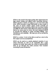
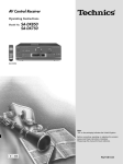
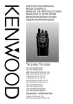
1
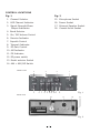
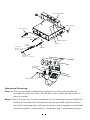
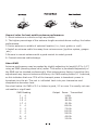
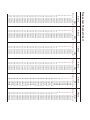
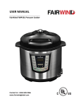
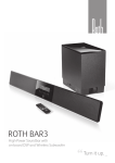
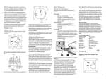
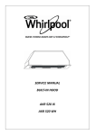
Operation
Manual
ARGO 300
240 Channel Mobile
AM / FM
Transceiver
General Description
This Model is a combination transmitter-receiver designed primarily for mobile use.
It employs the very latest technology to provide 240channels of operation by means of digital frequency synthesis with PLL (phase-locked-loop) circuitry.
The use of PLL assures a precise on-frequency operation on every channel in both transmit and receive mode. This model also includes many other features which
will provide greater operating convenience and assure optimum communications
under a wide range of conditions.
Operable on 240 channels divided into six groups of 40 channels.
Full noise reduction features - ANL and noise blanker.
2 modes of operation - AM, FM - selectable with switch.
RF power output switchable in 2 ways for required communication range.
External speaker jack for an extra sound source.
Electrically floating cliassis for negative ground operation without switching.
A high-sensitivity dynamic microphone equipment.
CAUNTION
FOR REPLACEMENT OF THE FUSE
IN DC POWER CABLE, PLEASE BE SURE
TO USE 2A FUSE.
2
Specifications
General
* Channel
: 240 channel (40CH X 6)
* Frequency composition
: Digital phase locked loop synthesizer
* Modulation mode
: AM/FM
* Frequency range
: Band A 26.065 ~ 26.505 Mhz
〃
B 26.515 ~ 26.955
〃
〃
C
26.965 ~ 27.405
〃
〃
D
27.415 ~ 27.855
〃
〃
E
27.865 ~ 28.305
〃
〃
F
28.315 ~ 28.755
〃
* Channel spacing
: 10 kHz
* Antenna impeadance
: 50 Ohm
* Power supply source
: 13.8 Volt DC(Only negative ground)
* Operating temperature
: -10℃ ~ +50℃
* Dimensions
: 160(W) X 55(H) X 210(D)mm
* Weight
: 1,100 g
Receiver
* Sensitivity
: AM
FM
1 uV,
S/N
10dB
1 uV, S/N
20dB
* Selectivity
: 60 dB
* Squelch range
: 0.2 uV ~ 500 uV
* IF
: 1 st 10.695 MHz ,2nd 455 KHZ
* Audio output power
: 2 watts at 8 Ohm
* Sprious response
: 50 dB
Transmitter
* RF output power
: AM/FM High 7 watt
Low 4 watt
* Frequency stability
:
0.005%
* Modulation capability
: AM 100%, FM
* Sprious emission
: 60 dB
3
2.5 Khz deviation max.
CONTROL LOCATIONS
Fig. 1
Fig. 2
1. Channel Selector
15. Microphone Socket
2. LED Channel Indicator
16. Power Socket
3. Signal Strength/Powe
17. External Speaker Socket
Output Indicators
18. Coaxial Acrial Socket
4. Band Selector
5. On / Off-Volume Control
6. Receive Indicator
7. Squelch Control
8. Transmit Indicator
9. RF Gain Control
10. AM Indicator
11. FM Indicator
12. R F power switch
13. Model selector Switch
14. ANL + NB /Off Switch
FRONT VIEW
4
5
3
6
7
8
2
9 10 11 12 13
REAR VIEW
18
1
Fig. 1
14
17
16
15
Fig. 2
4
Operating Controls and Features
1. Channel selector
A 40-detent rotary, switch to select any of 240 channels in conjunction with the
Band Selector switch.
Window above this switch indicates the channel selected using an LED (Light-emitting-diode)digital readout.
2.Channel indicator
A digital LED display to show channel selected.
Turned off when operating PA.
3.S/RF indicator
When an incoming signal is received the RX indicator will illuminate. and the signal
indicator will illuminate to monitor the relative strength of the signal. The strength
of the incoming signal will depend on the performance of the transmitter and aerial,
your distance from it and the nature of the surrounding area, not on your set’
s
ability to receive the transmitted signal.
Power output is registered by the LED indicators.
4.Band Selector
Selects a group of 40 channels in six positions - A, B, C, D, E or F (240 in all).
5.Off/Volume Control
Varies the sound output form the speaker. Also incorporates an on-off switch at the
extremely counterclockwise position.
6.RX indicator
Lights up when receiving.
7.Squelch Control
Used to eliminate any annoying background noise when no signals are present. The
degree of sensitivity to incoming signals is adjustable. When the Squelch control
is rotated to the fully clockwise position, it provides maximum squelch, in the fully
counterclockwise position, it provides minimum squelch.
8.TX indicator
Lights up when transmitting.
9.RF Gain Control
Selects RF Gain (receiver sensitivity) of the transceiver in variations.
MAX. In this position, the receiver section provides maximum sensitivity so that it
can pick up even weak signals.
Normally this switch should be placed in this position.
MIN. In this position, the receiver sensitivity is minimum, and the receiver will pick
up only the strong signals. May be used when receiving strong (close) signals which
are causing overload in receiving sound.
10. AM indicator
Lights up when operating AM
11. FM indicator
Lights up when operating FM
5
12. Power Selecto r
Enables you to select the RF power output of the transceiver in 2 ways.
High . In this position the transceiver produces full rated RF power for maximum
communication range.
LOW. In this position, the minimum R F power output is obtained, may be used for
short range communication.
13. Mode switch
Selects the mode of reception and transmission -AM (amplitude modulation).
FM (frequency modulation)
14.ANL + NB/Off Switch
In the upper position the ANL is activated lower position the ANL is off and in
together with the NB(noise blanker).
15.Microphone jack
Accepts plug form the microphone supplied. The jack has a locating key inside and
allows the plug inserted in only one way. Do not force the plug but align key way
properly onto the jack.
16. 13.8 V DC jack
13.8 V DC power for the transceiver supplied through this socket (using DC power
cable supplied).
17.Exermal Speaker jack
Used to connect an external speaker (8 Ohm 4 W) as an extra sound source.
Insertion of the plug from a speaker will silence the internal speaker automatically.
18. Antenna
Accepts a PL 259 type coaxial connector from the antenna lead-in cable.
Installation
Safety and convenience are the primary factors in deciding exactly where to locate
your transceiver. The transceiver is designed for ease in control accessibility .Be sure
that the unit is located so that it does not interfere with the driver or impair access to
any controls. Connecting cables must be routed and secured in such a controls.
Interference from either the operation of the brake, accelerator or other controls.
Interference from either the unit or connecting cables may contribute to the loss of
control of the vehicle.
The transceiver is designed for use with either negative or positive ground electrical
systems.
6
MOUNTING BRACKET
MOUNT SCREW 2
COAXIAL PLUG
WIREPLUG FROM EXT SP
TAPPING SCREW 3
WASHER 3
2A FUSE
HOLDER
12V Battery
Positive (+) Terminal
PLUS (+) WIRE
DC PLUG
MINUS(—)WIRE
12V Battery
Negative (—) Terminal
MICROPHONE
BRACKET
TAPPING SCREW 2 WASHER 2
Mechanical Mounting
Step 1: Use the mounting bracket as a template for marking the location of
screwholes under your dash. Use an awl, nail or other pointed object to
mark the metal.
Step 2: Drill a 3.2mm hole for each screwhole in the mounting bracket. Attach the
bracket to the dash with the machine screws provided. Extreme caution
should be exercised when drilling into dash to avoid damage to underdash
electronic ignition, cruise control, instrument and / or accessory wiring.
7
Step 1: With negative ground system, connect the red wire (one with in-line fuse
holder) to either the (a) fuse block, (b) cigarette lighter, or (C ) directly to
the positive post on the battery . Usually, the fuse block is the most convenient connecting point. It is also possible to connect to the Accessory
terminal on the fuse block or ignition switch, so that your CB unit automatically goes off, preventing accidental battery drainage. Then tightly
connect the black wire directly to the vehicle’
s metal frame.
Step 2: With positive ground system, reverse the wires, connecting the red/ fuseholder wire to the frame, the black wire to your DC power source. A light or
meter can be a good aid in locating a suitable power source and ground.
In either case, a good, direct metal-to-metal ground is essential for optimum performance.
Connect your antenna system to the antenna connector, If you are using an
external speaker or a PA speaker, connect it to the appropriate jack one
unit rear panel.
CB Antennas
Note: The licence requires that equipment which have provision for the connection
of an external antenna shall not be connected to other than a single element rod or
wire antenna not exceeding 1.5m in overall length.
For best reception and transmission, your radio should use an antenna especially
designed for a frequency of 27.7 MHz. Antennas are purchased separately and supplied with assembly and installation instructions, mounting hardware, and a coaxial
antenna cable fitted with a fully assembled standard connector (type PL-259) for
quick connection to your transceiver. CB antennas are available in many sizes and
styles. Base loaded quarter-wave antennas are most popular because they require
less space than full quarter-wave types and are easily installed.
These antenna types physically shorter but electrically equivalent to full quarte rwave whip antennas. We advise the use of base loaded whips of less than 1.5 meters.
The antenna’
s mounted location on the vehicle affects the operation of the radio.
Transmission and reception characteristics vary for different antenna locations, Three of the most popular antenna mountings are shown on next page.
Roof mount - The antenna mounted on roof represents a transmission/reception
range closest o ideal.
Front cowl mount - The radiation pattern is slightly greater in the direction of the
rear bumper opposite the side on which the antenna is mounted. Provides case in
antenna mounting.
Rear deck mount - The radiation pattern is strongest in the direction of the front
bumper opposite the side on which the antenna is mounted.
8
Roof Mount
Front Cowl Mount
Rear Deck Mount
General rules for best mobile antenna performanc e
1. Mount antenna on vehicle as high as possible.
2. The higher percentage of the antenna length mounted above rooftop, the better
performance.
3.Centre antenna in middle of selected location (i.e., boot, gutter or roof ).
4.Install an antenna cable line away from noise sources (ignition system, gauges
,etc.).
5.Be sure to mount antenna with a good mental-to-metal ground.
6. Prevent antenna cable damage.
About SWR
Antenna performance may be peaked by slightly adjusting its length(1/8〃to 1 /4〃)
using an SWR (standing wave ratio) meter. This meter is purchased separately or
the SWR can be checked professionally. Most antennas are factory-tuned,but this
adjustment may improve antenna efficiency. An SWR reading below 3:1 is desired,
as this indicates that over 75% of the transmit power is broadcast power is
broadcast into the air. The rest is‘reflected ’back into your transceiver and
dissipated as harmless heat.
See chart below. An SWR of 2:1 or below is good, 2.5 or even 3 is usually not user
noticeable or significant.
SWR Reading
1
:1
1.3 :1
1.5 :1
1.7 :1
2
:1
3
:1
4
:1
5
:1
6
:1
10 :1
Output
9
Power Transmitted
100%
98.3%
96.0%
93.3%
89.0%
75.0%
64.0%
58.0%
49.0%
33.0%
Channel Selection
The transceiver is capable of operation on 240 channels which are divided into 6
groups of 40 channels - A,B,C,D,E and F. These groups are selected with the Band
Selector switch as the following.
Band switch
Position
A
B
C
D
E
F
Frequency
26.065 to
26.515 to
26.965 to
27.415 to
27.865 to
28.315 to
Range
26.505
26.955
27.405
27.855
28.305
28.755
MHz
MHz
MHz
MHz
MHz
MHz
After the band to which the channel you desire to operate belongs is selected, rotate
the channel selector to find the channel. Rotating the channel selector clock-wise or
counterclockwise by 1 detent will tune the transceiver 10 kHz upscale or downscale.
i to operate on 27.405 MHz first set the Band selector switch to `c`,
C If you desire
then turn the channel selector to the position at which the channel readout shows
‘40 ’
.
Operation
(1) Turn the Volume control clockwise to apply power to the transceiver. The LED
display should be illuminated.
(2) Rotate the Squelch control counterclockwise fully.
(3) Select the mode of reception AM, FM.
(4) Set the RF Gain control maximum position.
(5) Select the channel desired.
(6) To transmit, depress the transmit switch on microphone, to receive, release
the switch.
RF Gain Control Ajustment
Normally, this control should be set to Max. Position to provide maximum receiver
sensitivity for long range reception. However, When communicating with a nearby
station, you may find that the strong signal from this station may cause overloading
of your receiver. In such a case. You can sue this control to reduce the receiver Sensitivity and thus prevent any overloading and distortion that may occur as a result of
the extremely strong incoming signals. First set the switch to center and if this position will not provide a sufficient reduction of overloading condition, set to minimum
Position.
10
Channel
1
2
3
4
5
6
7
8
9
10
11
12.
13.
14.
15.
16.
17.
18.
19.
20.
21.
22.
23.
24.
25
26.
27.
28.
29.
30.
31.
32.
33.
34.
35.
36.
37.
38.
39
40
Frequency
26.515
26.525
26.535
26.555
26.565
26.575
26.585
26.605
26.615
26.625
26.635
26.655
26.665
26.675
26.685
26.705
26.715
26.725
26.735
26.755
26.765
26.775
26.805
26.785
26.795
26.815
26.825
26.835
26.845
26.855
26.865
26.875
26.885
26.895
26.905
26.915
26.925
26.935
26.945
26.955
MHz
B-Band
Frequency/Channel Chart
A-Band
MHz
Channel Frequency
26.065
1
26.075
2
26.085
3
26.105
4
26.115
5
26.125
6
26.135
7
26.155
8
26.165
9
10 26.175
11 26.185
12. 26.205
13. 26.215
14. 26.225
15. 26.235
16. 26.255
17. 26.265
18. 26.275
19. 26.285
20. 26.305
21. 26.315
22. 26.325
23. 26.355
24. 26.335
25 26.345
26. 26.365
27. 26.375
28. 26.385
29. 26.395
30. 26.405
31. 26.415
32. 26.425
33. 26.435
34. 26.445
35. 26.455
36. 26.465
37. 26.475
38. 26.485
39 26.795
40 26.505
Frequency
26.965
26.975
27.985
27.005
27.015
27.025
27.035
27.055
27.065
27.075
27.085
27.105
27.115
27.125
27.135
27.155
27.165
27.175
27.185
27.205
27.215
27.225
27.255
27.235
27.245
27.265
27.275
27.285
27.295
27.305
27.315
27.325
27.335
27.345
27.355
27.365
27.475
27.385
27.395
27.405
MHz
C-Band
Channel
1
2
3
4
5
6
7
8
9
10
11
12.
13.
14.
15.
16.
17.
18.
19.
20.
21.
22.
23.
24.
25
26.
27.
28.
29.
30.
31.
32.
33.
34.
35.
36.
37.
38.
39
40
Frequency
27.415
27.425
27.435
27.455
27.465
27.475
27.485
27.505
27.515
27.525
27.535
27.555
27.565
27.575
27.585
27.605
27.615
27.625
27.635
27.655
27.665
27.675
27.705
27.685
27.695
27.715
27.725
27.735
27.745
27.755
27.765
27.775
27.785
27.795
27.805
27.815
27.825
27.835
27.845
27.855
MHz
D-Band
Channel
1
2
3
4
5
6
7
8
9
10
11
12.
13.
14.
15.
16.
17.
18.
19.
20.
21.
22.
23.
24.
25
26.
27.
28.
29.
30.
31.
32.
33.
34.
35.
36.
37.
38.
39
40
E-Band
MHz
Channel Frequency
27.865
1
27.875
2
27.885
3
27.905
4
27.915
5
27.925
6
27.935
7
27.955
8
27.965
9
10 27.975
11 27.985
12. 28.005
13. 28.015
14. 28.025
15. 28.035
16. 28.055
17. 28.065
18. 28.075
19. 28.085
20. 28.105
21. 28.115
22. 28.125
23. 28.155
24. 28.135
25 28.145
26. 28.165
27. 28.175
28. 28.185
29. 28.195
30. 28.205
31. 28.215
32. 28.225
33. 28.235
34. 28.245
35. 28.255
36. 28.265
37. 28.275
38. 28.285
39 28.295
40 28.305
F-Band
MHz
Channel Frequency
28.315
1
28.325
2
28.335
3
28.355
4
28.365
5
28.375
6
28.385
7
28.405
8
28.415
9
10 28.425
11 28.435
12. 28.455
13. 28.465
14. 28.475
15. 28.485
16. 28.505
17. 28.515
18. 28.525
19. 28.535
20. 28.555
21. 28.565
22. 28.575
23. 28.605
24. 28.585
25 28.595
26. 28.615
27. 28.625
28. 28.635
29. 28.645
30. 28.655
31. 28.665
32. 28.675
33. 28.685
34. 28.695
35. 28.705
36. 28.715
37. 28.725
38. 28.735
39 28.745
40 28.755