1
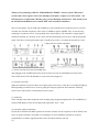
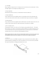
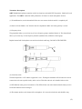
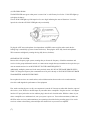
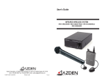
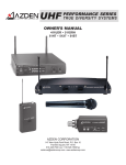
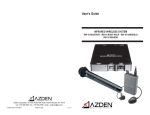
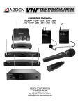
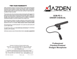
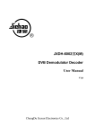
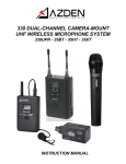
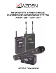
UHF PERFORMANCE SERIES TRUE DIVERSITY SYSTEMS OWNERS MANUAL 411UDR 411DRH 41HT 41HT3 41XT 41BT AZDEN CORPORATION 147 New Hyde Park Road Franklin Square, NY 11010 516.328.7500 vox 516.328.7506 fax [email protected] www.azdencorp.com Thank you for purchasing AZDENS PERFORMANCE SERIES wireless system. UHF wireless systems yield a better signal to noise ratio and improved frequency response over VHF systems. The UHF band is less crowded than VHF thus giving you less likelihood of interference. This manual covers the 411UDR and 411DRH receivers and the 41BT, 41XT and 41HT transmitters. Receiver Descriptions: The 411UDR and 411DRH are crystal controlled, PLL synthesized receivers with 63 on-board user selectable frequencies with a range of 794MHz to approx. 806MHz. They are true diversity, containing two separate receivers, each operating on the same frequency. The transmitters output signal is monitored constantly by a diversity circuit, which switches automatically to the receiver with the stronger RF signal. This allows wireless performance that is virtually drop-out free, even under the most adverse conditions. Both receivers feature a 1/4-inch and XLR output jacks and volume adjustment. 9 10 4 8 1 2 7 3 6 5 1 4 (1) Power LED and on/off switch (411DRH only) After plugging in the 411DRH, depress the on/off switch to turn unit on and illuminate the Power LED. The 411DRs Power LED will illuminate as soon as the unit is plugged in. (2) Antenna A-B LEDs When the transmitter is turned on and is in reception range of the receiver, either the A or B LED will light up RED, depending on which receiver circuit is getting the strongest signal from the transmitter. Flickering between the A and B LED is a normal function of the system. (3) Peak LED These will flash if the audio component of the incoming signal is approaching distortion. The 411DRH has a 7 segment LED display to show the incoming audio signal from -20 to + 6 dB. (4) Antennas, antenna connections On both the 411UDR and 411DRH, position the antennas vertically for best reception. On the 411UDR, when not in use put the antennas in the holder to avoid damage. On the 411DRH the antennas are connector mounted (BNC) so that the supplied antennas can be disconnected and/or removed. (1) (5) 12 Volt Input Plug the supplied AC adapter into the 12 volt input on the receiver then into an AC electrical outlet. Use only the adapter supplied, as other adapters may damage the receiver. (6) Output Adjustment Rotate this knob clockwise to increase, or counterclockwise to decrease volume level. (7) Output (unbalanced) Using a suitable audio cable (not supplied) connect the 1/4-inch phone jack end to the audio output on the receiver, and connect the other end of the cable to the suitable mic/line input of an audio mixer or amplifier. (8) Output (balanced) Using a suitable audio cable (not supplied) connect the XLR connector to the audio output on the receiver, and connect the other end of the cable to the suitable mic/line input of an audio mixer or amplifier. (9) & (10) Frequency select The group knob (9) allows you to select any of seven frequency groups (numbered from 0-6). The channel knob (10) allows you to select any of nine frequency channels (numbered 0-8) within the selected group. Any receiver/transmitter pair must be on the same group and frequency to operate properly. Be sure that both the transmitter and the receiver are OFF before selecting/changing the frequency. When using more than one system, all receivers and transmitters must be set to the same group to avoid intermodulation distortion while all transmitter/receiver pair must be on different frequencies. (11) Rack ears If you wish to use one or two 411DRHs in a standard 19" rack you must attach the rack ears (HR-1 or HR-2 purchased separately) by attaching the ears with the four machine screws (two per side near front). The HR-2 also requires the attachment of a joining plate underneath the two units. HR-1 (2) HR-2 The following feature is for the 411DRH only. (12) Squelch adjust This adjusts the point at which the receiver will shut off or squelch the incoming radio signal when it becomes too weak. Turning the control clockwise raises the threshold, allowing more signal to enter, and turning the control counter-clockwise lowers the threshold, letting in less signal. When operating multiple systems all receivers and transmitters must be on the same group Example: 4 systems operating simultaneously. System #1 System #2 System #3 System #4 Group Channel Group Channel Group Channel Group Channel Receivers 2 4 2 5 2 6 2 7 Transmitters 2 4 2 5 2 6 2 7 To change the frequency that a transmitter, receiver pair is already on YOU MUST TURN OFF BOTH TRANSMITTER AND RECEIVER OFF FIRST! (3) Transmitter Descriptions: 41HT Handheld microphone transmitter with 63 on-board user selectable UHF frequencies. Ideal for all vocal applications. The 41HT3 is identical in RF performance. It features an Audix microphone element. (1) To install batteries, turn the bottom half of the mic case counter-clockwise until it is completely off. (2) Insert two fresh alkaline AA batteries into the compartment. Make sure battery polarity is correct. (3) Frequency select The group knob allows you to select any of seven frequency groups (numbered from 0-6). The channel knob allows you to select any of nine frequency channels (numbered 0-8) within the selected group. Replace bottom half of microphone case and turn clockwise until snug. DO NOT OVER TIGHTEN. 6 (4) 2 Position switch The bottom position is Off and the top position is On. Turning the transmitter Off will cause the receiver to mute due to the tone squelch circuitry at the receiver. This allows the mic to be handled with no noise. (5) LED Indicator turns green when turned on. This LED will also turn red to indicate that the battery level is low and the batteries must be changed. (6) The antenna attaches to the bottom of the microphone. It is screwed on clockwise and should be snug. (4) 41BT body-pack transmitter with 63 on-board user selectable UHF frequencies. Ideal for use with lavaliere and headset microphones. The MP-1 instrument cable will also allow you to use the 41BT with electric guitars and basses. Please note: For use with instruments the gain structure of the 41BT must me modified at the factory. (1) Open the battery compartment lid by sliding it down and raising it. (2) Insert one fresh alkaline 9-volt battery into the compartment. Make sure battery polarity is correct. (3) Frequency select. The group knob allows you to select any of seven frequency groups (numbered from0-6). The channel knob allows you to select nine frequency channels (numbered 0-8) within the selected group. (4) Power and standby switches The power On and Off switch enables and disables all transmitter functions while the audio switch On and Standby turn the audio off and on. Switching the transmitter to Standby will cause the receiver to mute due to the tone squelch circuitry at the receiver. This allows the microphone to be handled with no noise. (5) LED Indicator turns green when turned on. This LED will also turn red to indicate that battery level is low and the battery must be changed. (6) Audio input Level Control enables you to adjust the input level of the microphone or musical instrument. Turn clockwise to increase, or counter-clockwise to decrease the input level. A small screwdriver is supplied to make these adjustments. The level control is factory-preset in the center position. (5) 41XT plug-in XLR transmitter with 63 on-board user selectable UHF frequencies. Ideal for use with dynamic microphones with XLR output. (1) Open the battery compartment lid by sliding it down and raising it (2) Insert one fresh alkaline 9-volt battery into the compartment. Make sure battery polarity is correct. (3) Frequency select The group knob allows you to select any of seven frequency groups (numbered from 0-6). The channel knob allows you to select any of nine frequency channels (numbered from 0-8) within the selected group. (4) Power and Audio switches The power On and Off switch enables and disables all transmitter functions while the Audio switch On and Off turn just the transmitters Audio signal on and off. Switching the Audio to Off will cause the receiver to mute due to the tone squelch circuitry in the receiver. This allows the microphone to be handled with no noise. (5) Audio input LEVEL control This enables you to adjust the input level of the microphone. Turn clockwise to increase, or counter-clockwise to decrease the input level. A small screwdriver is supplied to make adjustments. (6) (6) LED INDICATORS The POWER LED turns green when power is turned On or red if battery level is low. If this LED lights up red replace the battery. The AF PEAK LED lights up if the input level is set to high, indicating the onset of distortion. Lower the input level so that the AF PEAK LED lights only occasionally. To plug the 41XT onto a microphone (low impeadance with XRL connector) first make certain the the locking-ring is turned fully up (rotate counter-clockwise). Then plug the 41XT fully into the microphones XLR connector and tighen by rotating the ring fully down (clockwise). OPERATING THE SYSTEM: Because this a frequency agile system, meaning that you choose the frequency of both the transmitter and receiver via the group and channel controls, we cannot stress enough that any transmitter/receiver pair that you want to transmit and receive on MUST BE SET TO THE SAME FREQUENCY! Additionally, multiple systems used in the same proximity must ALL BE ON THE SAME GROUP SELECTION! To change the frequency that a transmitter/receiver pair is already on YOU MUST TURN OFF BOTH TRANSMITTER AND RECEIVER FIRST! Do not place the receiver on a metal surface, and avoid obstructions between the receiver and transmitter, since this could degrade the performance of the equipment. First, make sure that the power to all your components is turned off. Connect an audio cable from the output of the receiver (1/4 or XLR) to a mic/line input on your audio mixer or amplifier. Plug the receivers AC adapter into the 12V input jack on the receiver and then plug it into the AC electrical outlet. With the volume of your mixer or amplifier set to minimum level, turn your systems power on. Turn on the transmitter(s). Make sure all LEDs on the receiver(s) and transmitter(s) are operating as described in the preceding pages. Now set the receivers volume to the midway point and adjust the volume level on your mixer or amplifier. (7) 41BT with Lavaliere or Headset: With someone talking into the microphone, turn the volume on the mixer or amplifier to the desired level. If there is too much, or not enough gain, lower or raise the volume on the receiver. If the sound is distorted, lower the input gain on the transmitter. 41BT with Instrument cable for electric guitars or basses (MP-1): Plug the cable into the guitar or bass. Set the instrument volume to the midway point. While playing the instrument, turn the volume on the mixer or amplifier to the desired level. If there is too much, or not enough gain, lower or raise the volume on the receiver. If the sound is distorted, lower the input gain (6) on the transmitter. 41XT: With someone talking into the microphone, turn the volume on the mixer or amplifier to the desired level. If there is too much, or not enough gain, lower or raise the volume on the receiver. If the sound is distorted, lower the input gain on the transmitter. 41HT: With someone talking/singing into the microphone, turn the volume on the mixer/amplifier to the desired level. If there is too much, or too little gain, adjust the volume on the receiver. If the sound is distorted, move the microphone further away from the sound source. Make sure that the LED is green when the mic/transmitter is turned On. When the battery is low, the LED turns red indicating that the battery needs to be changed. NOTES: - All Performance Series transmitters will work continuously for approximately 6-8 hours using an alkaline battery. - Remove the battery if the transmitter will not be used for a long period of time. - Do not use or store the system in areas of high temperatures or humidity. - Do not use this system near a broadcast station, airport, or airplanes, it may cause interference. If you are interfering with other transmissions you must turn off the system. - These systems contain no user serviceable parts. If unauthorized service is performed it may void the warranty. (8) Specifications Overall: Frequency Range: UHF 63 ch.(793-806MHz) Frequency Response: 20Hz to 20kHz Audio Distortion: less than 1% Dynamic Range: better than 100dB S/N Ratio: better than 95dB Operating Temperatures: 0 to 45 Operating Range: 100m under ideal conditions Oscillator: PLL synthesized Tone Squelch Frequency: 32.768kHz Diversity Type: True Space Diversity 41BT Transmitter: Type of Emission: FM Antenna: External Antenna Pre-emphasis: 50 ms MAX Input Level: -10dBm(Mic) +7dBm(MP-1) Microphone Unit: Lav or Headset RF Output Power: 15mW (50mW MAX) Input Impedance: 2.2K (Mic) 680K (MP-1) Audio Adj Range: m/2 Battery: 9V Battery Life: 6 to 8 hours with Alkaline Battery Dimensions: 100(H) 62(W) 22(D) mm Weight: 92g (without battery) FCC Notes: These systems conform to part 74 and part 15 of the FCC rules, and you should contact the FCC office for filing forms. (9) 41HT/41HT3 Transmitter: Type of Emission: FM Antenna: Internal Antenna Microphone Unit: Unidirectional Dynamic RF Output Power: 10m W (50mW MAX) Input Impedance: 8K Audio adj Range: m/2 Battery:2 1.5V (AA) Battery Life: 6 to 8 Hours with Alkaline Battery Dimensions: 56(D) 242(L) mm Weight: 250g (without battery) 41XT Transmitter: Type of Emission: FM Antenna: Internal Antenna Pre-emphasis: 50 ms MAX Input Level: -7dBm Microphone Unit: Dynamic Microphones RF Output Power: 15mW (50mW MAX) Input Impedance: 6K Audio Adj Range: m/2 Battery: 9V Battery Life: 6 to 8 hours with Alkaline Battery Dimensions: 40 x 40 x 99(L) mm Weight: 152g (without battery) UHF FREQUENCY CHART CHANNEL GRP 0 1 2 3 4 5 6 7 8 0 794.500 795.750 797.750 798.000 799.500 800.500 802.375 804.7850 805.875 1 794.375 795.625 797.625 797.875 799.375 800.375 802.250 804.625 805.750 2 793.750 795.000 797.000 797.250 798.750 799.750 801.625 804.000 805.125 3 794.250 795.500 797.500 797.750 799.250 800.250 802.125 804.500 805.625 4 794.125 795.375 797.375 797.625 799.250 800.125 802.000 804.375 805.500 5 794.000 795.250 797.250 797.500 799.000 800.000 801.875 804.250 805.375 6 793.875 795.125 797.125 797.375 798.875 799.875 801.750 804.125 805.250 (10)