1
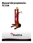
100381
REV F, ECO 14-0098
Owner’s Manual
M200
Waste Compactor
™
www.radiaproducts.com
™
Contents
OVERVIEW AND SAFETY FEATURES . . . . . . . . . . . 3
SET UP
Unpacking. . . . . . . . . . . . . . . . . . . . . . . . . . . . . . . . . . . 4
Selecting the Location. . . . . . . . . . . . . . . . . . . . . . . . . . 4
Preparing to Compact. . . . . . . . . . . . . . . . . . . . . . . . . . 4
Inspecting the Unit. . . . . . . . . . . . . . . . . . . . . . . . . . . . . 4
Installing the Compactor Bag . . . . . . . . . . . . . . . . . . . . 4
OPERATING THE UNIT
Powering up the Unit. . . . . . . . . . . . . . . . . . . . . . . . . . . 5
Operation. . . . . . . . . . . . . . . . . . . . . . . . . . . . . . . . . . . . 5
Functions of the Indicator Lights. . . . . . . . . . . . . . . . . . 5
Emptying the Unit . . . . . . . . . . . . . . . . . . . . . . . . . . . . . 5
MAINTENANCE AND SERVICE
Preventive Maintenance Schedule. . . . . . . . . . . . . . . . 6
Cleaning the Compaction Plate. . . . . . . . . . . . . . . . . . . 6
Lockout/Tag out Procedure. . . . . . . . . . . . . . . . . . . . . . 7
Lockout/Tag out Checklist. . . . . . . . . . . . . . . . . . . . . . . 8
TROUBLESHOOTING . . . . . . . . . . . . . . . . . . . . . . . . . 9
SCHEMATICS
Wiring Harnesses . . . . . . . . . . . . . . . . . . . . . . . . . . . . . 11
Electrical Schematic . . . . . . . . . . . . . . . . . . . . . . . . . . . 12
REPLACEMENT PARTS
Ordering Info. . . . . . . . . . . . . . . . . . . . . . . . . . . . . . . . . 13
Cabinet Bottom. . . . . . . . . . . . . . . . . . . . . . . . . . . . . . . 14
Cabinet Middle . . . . . . . . . . . . . . . . . . . . . . . . . . . . . . . 15
Cabinet Top. . . . . . . . . . . . . . . . . . . . . . . . . . . . . . . . . . 16
Compactor Hydraulics. . . . . . . . . . . . . . . . . . . . . . . . . . 17
Load Door Assembly. . . . . . . . . . . . . . . . . . . . . . . . . . . 18
Bin Door Assembly. . . . . . . . . . . . . . . . . . . . . . . . . . . . 19
Panels. . . . . . . . . . . . . . . . . . . . . . . . . . . . . . . . . . . . . . 20
Bin Assembly. . . . . . . . . . . . . . . . . . . . . . . . . . . . . . . . . 21
WARRANTY. . . . . . . . . . . . . . . . . . . . . . . . . . . . . . . . . 22
2
™
M200 Compactor Operation and Maintenance Manual
With just a little preventive maintenance and regular cleaning, we are sure your M200 compactor will
provide many years of trouble-free operation.
Please read this manual carefully before installing or servicing the equipment.
OVERVIEW AND SAFETY FEATURES
The M200 compactor can save thousands of dollars over its life by reducing
trash hauling expenses and labor. It can reduce the volume of solid waste by as
much as 90%.
The compactor consists of a powerful hydraulic pump coupled to a 1.5”
diameter cylinder that generates 1 ton of compaction force.
The M200 compactor utilizes a high capacity waste bin and a
durable, puncture resistant bag. When the loading door is opened and then
closed, the compaction cycle initiates automatically.
This equipment has built-in safety features to protect you and your employees.
Each door is equipped with a safety switch that prevents compaction if any of
the doors are open. In addition, the waste loading door has a lock feature that
keeps it from being opened during compaction.
Waste Door
Lower Bin Door
Safety limit switch for
the lower bin door
3
Safety limit switch for
the load door
August 2005
™
M200 Compactor Operation and Maintenance Manual
SET UP
Unpacking
Refer to included document #100382 Set-Up Guide for unpackaging instructions.
Selecting the Location
The correct location of the Compactor will make it more useful as well as easier to operate and
service.
• Make sure there is a 110 volt, 20 amp circuit available and within electrical cord distance—
DO NOT USE AN EXTENSION CORD.
• Make sure there is enough clearance to remove the waste bin when the lower door is open
completely.
Preparing to Compact - IMPORTANT!
Before operating the compactor, you must remove the red plug from
the hydraulic pump fluid reservoir and replace it with the breather
valve cap taped to the machine. Then, install the top cover to the
compactor using the screws taped to the inside of the cover. Refer
to the included 100382 Set-up Guide for detailed instructions.
Inspecting the Unit
1. Remove the packing materials from the unit. Inspect for any damage that may have been missed
when the unit was delivered and report it to Radia Products™ customer service.
Each Compactor comes with the following:
• One (1) Starter Package of specially designed Compactor Bags
• One (1) Waste Bin
2.
3.
4.
5.
To set up the unit, open the lower door by sliding the latching bolt up and to the left.
Remove the plastic waste bin from the compactor.
Remove the package of bags from the bin and set them aside.
Install a bag onto the waste bin using the instructions below
Installing the Compactor Bag
1. Pull the cart from the unit using the attached handle.
2. Remove a single bag from the starter package and place it in the bin.
3. Fold the excess over the outside edge of the bin as shown in the figure below and then fold
it back up to form a cuff. This will help prevent liquids from flowing over the bag during the
compaction cycle.
4. Place the elastic cord over the bag and under the bin lip to hold the bag in place, as shown in the
photo.
5. Lift and push the bin completely into the compactor.
6. Close the lower door and slide the latching bolt down
and to the right to secure the door closed.
4
™
M200 Compactor Operation and Maintenance Manual
Powering Up the Unit
The electrical cord is located on the back of the unit. Plug it into a grounded outlet. Note:
The standard compactor is wired to operate on 110-120 volts/20 amps, single phase
electrical power.
Operation
1. Rotate the handle on the waste loading door.
2. Open the door and place trash in the compactor.
3. Close the load door and turn the handle to latch the door closed.
4. Once the door closes, compaction automatically starts.
5. The load door is locked until the compaction plate retracts to its home position.
Functions of the indicator lights
• The green light indicates that the machine is compacting
• The orange light indicates that the waste bin is
full
• The red light indicates that an error has
occurred
Emptying the Unit
1. Open the lower bin door of the compactor.
2. Pull waste bin from the unit.
3. Pull the sides of the bag up and secure with a twist tie (not provided) or by tying a knot.
4. If desired, use the bin to transport the bagged waste to the dumpster.
5. Remove the bag and dispose of the waste.
6. When the bin has been emptied, install a new bag in the bin.
7. Slide the waste bin back into the compactor and close the lower bin door.
5
August 2005
™
M200 Compactor Operation and Maintenance Manual
MAINTENANCE AND SERVICE
Clean top of plate
Wipe down outside of cabinet
Clean inside of cabinet
Check hydraulic fluid level*
Check for loose fasteners, etc.
Daily
X
Weekly
Monthly
Quarterly
X
X
X
X
*To check fluid level, the compaction plate must be all the way up. Hydraulic fluid should be 2/3
the way up the sides of the see through tank. If the fluid level is low, it can be replenished by adding
Dexron ATF transmission fluid, available at most auto parts stores. Make sure to filter the fluid to
avoid getting foreign particles into the hydraulic components of the compactor, as this could affect
the life expectancy as well as the warranty of your machine.
Cleaning the Compaction Plate
From time to time, trash may become lodged on top of the compaction plate. This may cause the
unit to malfunction unless it is removed. We recommend you check the plate whenever you empty
the compactor.
1. Open the lower door and remove the waste bin.
2. Close the lower door and open then close the load door to start a compaction cycle.
3. After a few seconds, UNPLUG THE UNIT to stop the compaction plate.
4. Open the lower door and clean paper and debris from the top of the plate.
5. Close the lower door and plug the compactor back in to retract the compaction plate.
6. Open the lower door and replace the waste bin.
7. Close the lower door and slide the latch to lock it in place.
Compaction Supplies
You can keep your new compactor operating efficiently by only using genuine Radia Products™
replacement bags and parts
• 100 count box of replacement bags made of heavy 3-mil, metallocene polyethylene, which
reduces punctures and tears and prevents leaks
• Poly bonnets help keep the compaction plate clean (not included)
• Optional TC50 Transport Cart with hoist to lift heavy waste loads into dumpster
6
™
M200 Compactor Operation and Maintenance Manual
Compactor Lockout/Tagout Procedures
RESPONSIBILITIES:
Owner/Employer – Implementation of the lockout/tagout procedure and enforcement of its provisions is the
responsibility of the employer. It is a further responsibility of the employer to ensure that all personnel are informed and
trained in the application of the procedure.
Operator/Employee – Each individual working on equipment covered by this procedure has the responsibility of
conforming to the applicable provisions.
Procedure:
1. Notify all affected employees you will be locking out a compactor and let them know the reason why. A
lockout/tagout checklist form shall be utilized to assure all sources of energy are isolated. The completed
lockout/tagout checklist must be retained as long as the equipment is down for service and/or maintenance.
2. Standard shutdown: If the compactor is operating, shut it down by the normal stopping procedures. Close the
access door and wait for compaction cycle to finish. Turn machine power switch to off position.
3. Disconnect: Unplug compactor.
Energy Type/Magnitude
115 volt electrical
Isolating Device
Power cord
Location
Back of machine
Procedure
Turn off machine and unplug
4. Stored Energy Release: Although it could fall at any time, once hydraulic pressure is relieved, the ram plate WILL fall
due to gravity and so must be blocked or restrained. To relieve pressure hold hose and rock gently while slowly loosening
the fitting. Wear safety glasses and keep hands away from fitting while loosening to prevent injury.
Hazard
Ram plate may fall due to gravity
Equipment Needed
Placement
Block or restraining device
Beneath ram plate
Hydraulic fluid pressure --- C500, LP1000 = 2500 psi --- M200, R200 = 1200 psi
5. Compactor can be locked out by placing a lockable cover over the electrical plug while repairs are made. Place a tag
that states “Danger – do not operate” or equivalent on the front of the compactor near the controls.
6. Lockout/tagout Assurance Tests: After ensuring no personnel are exposed, and the compactor is unplugged, attempt to
start a compaction cycle to make certain the equipment will not operate.
Control(s) to try
Open and close load door, start button (if applicable)
Procedure to verify isolation
Attempt to start compaction cycle
7. The compactor is now locked out.
Restoring Machines or Equipment to Normal Operations:
1. After all servicing and/or maintenance is completed and equipment is ready for normal operations, check the area
around the machine or equipment to ensure that no one is exposed.
2. After all tools have been removed from the machine or equipment, guards have been reinstalled and employees are in
the clear, remove all lockout devices, plug in the power cord to restore energy to the machine or equipment.
7
August 2005
™
M200 Compactor Operation and Maintenance Manual
LOCKOUT/TAGOUT CHECKLIST
1.
Employee Notification
I have notified all affected employees that a lockout is required for this piece of equipment.
Date:
Time:
Signature:
2.
Shutdown
I understand why, after following normal procedures, the equipment is to be shut down.
Date:
Time:
Signature:
3.
Disconnection of Power Source
I have checked all operating switches and unplugged the compactor. I have blocked or restrained
the ram plate.
Date:
Time:
Signature:
4.
Lockout
I have locked out or tagged out the energy isolating devices with locks and/or tags designated for this
purpose.
Date:
Time:
Signature:
5.
Safety Double Check
After ensuring that no employees are exposed, and as a check on having disconnected all energy
sources, I have operated the start button or other normal operating control to make certain that the
equipment will not operate, and returned the operating control to neutral or off.
THE EQUIPMENT IS NOW LOCKED OUT
August 2005
8
™
Troubleshooting
Problem
The waste loading door
won’t open and the red light
is repeatedly flashing a twoflash pattern
The red light is repeatedly
flashing a three-flash
pattern
Machine either won’t
compact properly or doesn’t
shut off immediately at the
end of compaction; red light
is repeatedly flashing a
four-flash pattern
Machine won’t compact
properly; red light is
repeatedly flashing a fiveflash pattern
9
Cause
Solution
The waste load door is open
Close the load door
Trash stuck in load chute –
load door can’t close
Clear trash from the load chute
Load door sensor isn’t sensing
the door being closed
Check electrical connections to the load
door sensor
Load door sensor defective
Replace Load door sensor
Lower bin door is open
Close the lower bin door
The magnetic sensor on the
lower bin door isn’t sensing the
door
Check electrical connections to the sensor
The magnetic sensor for the
bin door is defective
Replace magnetic sensor
Compaction plate is obstructed
from getting to “Home” position
Unplug machine and clear debris from
compaction plate area
The “Home” limit switch isn’t
being triggered at the end of
compaction
Check to make sure the guide rod that triggers
the “Home” switch isn’t loose. If it is loose,
tighten the fasteners holding the ram plate to
the guides rods and hydraulic cylinder. Use
Blue 246 Loctite on the screws.
Check electrical connections to the “Home”
limit switch
The “Home” limit switch is
defective
Replace the limit switch
Pressure switch on the
hydraulic cylinder is not
working
Check electrical connections to the pressure
switch at the top of the hydraulic cylinder
Pressure switch is defective
Replace the pressure switch
Solenoid valve on the power
unit isn’t working correctly
Check electrical connections to the solenoid
valve
Solenoid valve is defective
Replace solenoid coil and valve
™
Troubleshooting
Problem
Cause
Solution
Machine won’t compact, red light
is repeatedly flashing a sevenflash pattern
Pump contactor relay isn’t working
Check electrical connections to the
pump contactor relay
Pump contactor relay is defective
Replace pump contactor relay
Waste bin was full when power to
compactor was turned on
Check waste bin and empty if
needed
The “Full Bin” limit switch is
defective
Replace “Full Bin” limit switch. The
switch can simply be disconnected
in the short term to allow compactor
to operate, but will not notify user
when full until switch is replaced.
Machine is unresponsive, red
light is repeatedly flashing an
eight-flash pattern
Check that machine is plugged in
Compactor is unresponsive – no
error light
No power to compactor
Check wall circuit breaker
Unplug machine and check fuse on
control panel inside compactor
Compactor has power but won’t
compact trash – no error light
Low hydraulic fluid level
Check fluid level in pump reservoir
and add fluid as necessary. Fluid
reservoir should be approximately
¾” full when cylinder is at the home
position
Compactor won’t compact trash,
amber light is turned on
Waste bin is full
Empty the waste bin to reset the Full
light
“Full Bin” limit switch is set too low
Raise the “Full Bin” limit switch
“Full Bin” limit switch is defective
Replace the “Full Bin” limit switch.
The waste bin is very full but
amber light never turns on
10
™
Wiring Diagrams
Wiring Harnesses
500315
LOAD DOOR
MAG SWITCH
TO J4
500460 PLUG HOUSING
2X 500461 MALE PINS
8 7 6 5 4 3 2 1
8
2
16 15 14 13 12 11 10 9
2
8
16
PINS 1, 4, 7, 9, 14, 15 UNUSED
13 11 JB1 5 3
12 10 8 6
2
500572 HARNESS B
JB3
2X 5784940 3/16 MALE TERMINAL
8 RED
2, BLACK
500315
BIN DOOR
MAG SWITCH
8, RED
3 BLUE
16 BLACK
500333 RED LIGHT
ERROR
12 RED
16 BLACK
500373 GREEN LIGHT
COMPACTING RUN
11 GREEN
16 BLACK
500374 AMBER LIGHT
FULL INDICATOR
6 BLUE
10 ORANGE
8 RED
500316
BIN FULL SWITCH
NC
900216
EXTENDED
PRESSURE
SWITCH
16 BLACK NO
NO
13 BLUE
NC
500316
RAM UP SWITCH
NO
8 RED NO
5 BLUE
500454 HARNESS A
500453 CONTROL PANEL
4X 900465 MOUNTING STANDOFFS
TO J1
22
23 BROWN
23
24
24 BROWN
500359
MAIN
POWER
SWITCH
16
22 BLUE
500520
DC COIL
900224
PUMP
DIRECTION
VALVE
16 BLUE
2X 5786244 1/4 MALE TERMINAL
TO J2
GREEN
WHITE
27
26
28
GROUND
W2 U2 V2
U1 V1 W1
500508
HYDRAULIC
POWER
UNIT W/DC
COIL
BLACK
500456 PLUG HOUSING
3X 500457 MALE PINS
TO J3
BLACK
500464 CORD, POWER UNIT
WHITE
25
26
27
GREEN
500462 RECEPTACLE HOUSING
3X 500463 FEMALE PINS
11
500396
POWER CORD
™
Wiring Diagrams
Electrical Schematic
12
™
Ordering Information
How to Order Replacement Parts
Replacement parts can be ordered from Radia Products™ by mail, telephone, or
FAX:
Radia Products™
14900 21st Ave North
Plymouth, MN 55447
763-852-1820
800-543-8722
763-852-181 (FAX)
If you need help in determining the proper part(s) to order, call 1-800-543-8722
and ask for Customer Service.
Always indicate the Model No. and Serial No. of the machine when ordering
replacement parts.
General Parts Replacement Policies
While your machine is under warranty, do not attempt on-site repair or parts
replacement without first contacting Radia Products™ CO. (to protect your
warranty). After the warranty expires, on-site servicing and parts
replacement are available from Radia Products™. Contact
Customer Service for arrangements and costs. Subsequent service cost
quotations may be affected unless Radia Products™ replacement parts (or their
approved equivalent) are used.
Restocking Fee
A restocking fee will be charged on all unused parts which are returned.
13
™
Exploded Views
Cabinet Bottom
2
1
3
1
2
3
PART NO.
900214
9783244
9780343
DESCRIPTION
Fixed Caster
Carriage Bolt ¼-20 x .75
Nut, Nylon Lock ¼-20
PART NUMBERS LISTED MAY ONLY BE AVAILABLE IN KIT FORM OR AS AN ASSEMBLY
14
™
Exploded Views
Cabinet Middle
9
6
5
8
7
7
1
2
14
4
11
16
17
10
2
15
20
12
19
18
13
4
5
3
5
1
2
3
4
5
6
7
8
9
10
PART NO.
900571
9780182
500315
9786300
9783595
9786277
9783605
500316
9782407
900468
DESCRIPTION
Full Switch Bracket
Nut, Nylock 5/16-18
Magnetic Proximity Switch
Screw, Flat Hd, Ph #4-40 x .75
Nut, Nylon Lock #4-40
Screw, Pan Hd, Ph #4-40 x .75
Washer, Flat #4-40
Limit Switch
Screw, Hex 5/16-18 x .75
Latch, Door Lock
3
11
12
13
14
15
16
17
18
19
20
PART NO.
900469
900470
900472
9780193
9781823
9100731
9786475
9786476
900560
9786474
DESCRIPTION
Bronze Flanged Bearing
Steel Bushing
Torsion Spring
Nut, Nylock 3/8-16
Washer, Flat 1/4-20
Washer, Flat 3/8-16
Washer, Wave 1/2-13
Bolt, Shoulder 3/8-16 x .625
Steel Ball Bearing
Washer, SS 3/8-16
PART NUMBERS LISTED MAY ONLY BE AVAILABLE IN KIT FORM OR AS AN ASSEMBLY
15
™
Exploded Views
Cabinet Top
1
2
3
4
5
6
7
8
9
10
PART NO.
900253
9784886
500316
500401
500403
500402
5782445
9783595
9786277
9783605
DESCRIPTION
Main Frame Weldment
Strain relief bushing
Limit Switch
LED, Red
LED, Amber
LED, Green
Power Switch
Nut, Nylon Lock #4-40
Screw, Pan Hd, Ph #4-40 x .75
Washer, Flat #4-40
PART NUMBERS LISTED MAY ONLY BE AVAILABLE IN KIT FORM OR AS AN ASSEMBLY
16
™
Exploded Views
Hydraulics
12
15
17
17
3
1
10
4
7
10
8
4
14
9
10
6
10
16
5
6
13
2
11
1
2
3
4
5
6
7
8
9
10
11
PART NO.
500508
900191
900216
900245
900254
900255
900310
900311
9785565
9785472
9786289
DESCRIPTION
Hydraulic 750W 1-Stage Power Unit
Ram Plate
Pressure Switch – 1000 PSI
Guide Rod Bushing
Hydraulic Cylinder
Guide Rod
Power Unit Mounting Block
Power Unit Damping Pad
Screw, SHCS, M10X1.5 x 60mm
Retaining Ring, C-Style, Ext, Ø1.50
Screw, Flat Hd, Socket ½-13 x 1.25
12
13
14
15
16
17
PART NO.
500453
9780192
9780193
900088
900368
900385
NOT SHOWN
900391
900392
11
11
DESCRIPTION
Control Panel Assembly
Screw, Hex 3/8-16 x 1.50
Nut, Nylon Lock 3/8-16
Hydraulic Fitting, 90°
Hydraulic Fitting, Straight
Hydraulic Fitting, Straight
Hydraulic Hose, 22”
Hydraulic Hose, 22”
PART NUMBERS LISTED MAY ONLY BE AVAILABLE IN KIT FORM OR AS AN ASSEMBLY
17
™
Exploded Views
Load Door Assembly
7
2
1
5
8
4
3
8
10
11
6
9
PART NO.
1 900551
2900183
3 900552
4 900553
5 900471
6900203
7 900204
8 9781840
9 9786263
10 9782055
11 9784042
DESCRIPTION
Load Door
Latch
Bracket – Right
Bracket – Left
Lock Bracket
Hinge
Latch Cam
Nut, Keps #8-32
Blind Rivet, Ø.156 - .126-.187 Thk
Washer, Lock #10, External Teeth
Screw, Pan Hd, Ph #10-32 x .375
PART NUMBERS LISTED MAY ONLY BE AVAILABLE IN KIT FORM OR AS AN ASSEMBLY
18
™
Exploded Views
Bin Door Assembly
6
3
5
7
8
1
2
4
PART NO.
1900186
2 900201
3900202
4 9786263
5 9786265
6 9786266
7 9786296
8 9786297
DESCRIPTION
Latch
Bin Door
Hinge
Blind Rivet, Ø.156 - .126-.187 Thk
Screw, Button Hd, #6-32 x .25
Nut, Acorn #6-32
Screw, Flat Hd, Ph #10-32 x .375
Nut, Acorn #10-32
PART NUMBERS LISTED MAY ONLY BE AVAILABLE IN KIT FORM OR AS AN ASSEMBLY
19
™
Exploded Views
Panels
3
4
5
1
5
2
1
2
3
4
5
PART NO.
900180
900181
900189
9786284
9786497
DESCRIPTION
Front Panel
Back Panel
Top Cover, Dome
Screw, Pan Hd, Ph #8-18 x .50 Self-Threading
Screw, Phllips TF, Ph #10-16 X .75 LG
PART NUMBERS LISTED MAY ONLY BE AVAILABLE IN KIT FORM OR AS AN ASSEMBLY
20
™
Exploded Views
Bin Assembly
2
1
4
6
3
5
1
2
3
4
5
6
PART NO.
900165
900166
900205
900451
9784698
9159200
NOT SHOWN
900251
DESCRIPTION
Lower Molded Bin
Upper Molded Bin
Bin Caster
Waste Bin Handle
Screw, Hex ¼-20 x .50
Screw, Hex ¼-20 x .75
Bin Cord, Small
PART NUMBERS LISTED MAY ONLY BE AVAILABLE IN KIT FORM OR AS AN ASSEMBLY
21
™
Compactor Standard Warranty
Equipment
Radia Products™ warrants (parts and labor) it’s Commercial Trash
Compactor equipment, accessories and parts against defective material or
workmanship for a period of one year after date of first delivery provided that Buyer
sends to Radia Products™ notice of the defect within thirty (30) days of its
discovery and clearly establishes that (i) the equipment, accessories or parts have
been properly maintained and operated within the limits of rated and normal usage
and (ii) the defect did not result in any manner from the intentional or negligent action
or inaction of Buyer. If buyer cannot establish that conditions (i) and (ii) have been
met, then this warranty shall not cover the alleged defect. Failure to give notice of
defect within such period shall be a waiver of the Warranty and any assistance
rendered thereafter shall not extend or revive it. This warranty shall not cover misuse,
alteration, abuse, negligence, accident, acts of God, sabotage or any item on which
serial numbers have been altered, defaced or removed, but shall be limited to repair
or replacement by Radia Products™ of those parts which, upon inspection by Radia
Products™, appear to have been defective in material or workmanship. This warranty
is limited to the Buyer and is not assignable or otherwise transferable without the
consent of Radia Products™.
This warranty is expressly in lieu of and excludes all other warranties, express or
implied, (including any warranty of merchantability and fitness of any product or
goods for a particular purpose) and all other obligations or liabilities on Radia
Products™ parts, and Radia Products™ neither assumes nor authorizes
any other person to assume for Radia Products™ any other liability in
connection with the sale of Radia Products™. There are no warranties which extend
beyond the description on the face hereof.
Limitations of Remedy
It is agreed that the liability of Radia Products™ shall be limited exclusively to the
remedies of repair or replacement of defective parts covered by the warranty set forth
in the paragraph Warranty on Equipment above and that such repair and replacement
shall be Buyer’s sole and exclusive remedy. Radia Products™
shall not have any liability whatsoever for loss of use or for any other incidental,
consequential or other damages or losses resulting from a breach of warranty
such as, but not by way of limitation, labor costs, loss of profits, loss of use of other
equipment, third party repairs, personal injury, emotional or mental distress, improper
performance of work penalties of any kind, loss of service of personnel, or any other
damages or losses which may be experienced by the Buyer.
August 2005
™
Contact Information
For sales or service, please contact
Customer Service:
Radia Products™
Attn: Compactor Dept.
14900 21st Ave N
Plymouth, MN 55447
U.S. Tel. 800.543.8722
International 763.852.1820
Fax 763.852.1811
[email protected]
™
www.radiaproducts.com.com
Copyright 2014 Radia Products™ Company. All rights reserved.