1
CC2430
9
Using SmartRF®04EB for prototyping
SmartRF®04EB includes a debug and programming interface. The debug interface is
controlled by 2 communication pins. On the SmartRF®04EB the interface is controlled by the
USB MCU. This allows both programming and an emulator interface using the USB port.
Table 1 on page 8 shows which pins on the MCU that are used for various peripheral
functions. P10 and P11 pin-row connectors can be used to connect the SmartRF®04EB to
another PCB or prototyping board.
9.1
Using SmartRF®04EB as an In-Circuit Emulator (ICE)
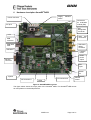
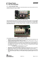
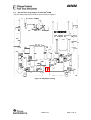
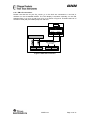
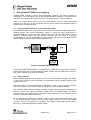
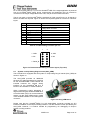
The SmartRF®04EB can be used as ICE both for devices connected to the EM socket and for
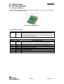
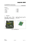
external systems with custom applications. Figure 14 shows the main components on
SmartRF®04EB when it’s used as ICE. Please notice that if the SmartRF®04EB is used to
debug an external system, the EM shall be removed, and vice versa. It is strongly
recommended to use the SOC_DEM in the EM connector slot when the SmartRF®04EB is
used to debug an external system, please see section 9.3.
Figure 14: SmartRF®04EB used as ICE
If several SmartRF®04EB boards are connected to the USB ports simultaneously a selection
window will display the connected SmartRF®04EBs, and the user can select which device to
load. This is valid for all Chipcon PC software.
9.2
Debug interface
When designing applications with Chipcon SoC’s it is recommended to include a pin header
or test points to allow in-circuit emulation or programming using SmartRF®04EB or other
programming tools.
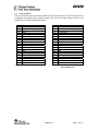
The pin-out used on the SmartRF®04EB is explained in Table 4. The connector includes 4
SPI control signals. These are currently not used, but they are included for flexibility.
The SmartRF®04EB includes a voltage converter to support programming and debugging of
external systems with different operating voltage than the SmartRF®04EB. The debug
connector (P14, “SoC debug/ flash”) includes two VDD connections on pin 2 and pin 9. The
function is different for these connections.
Pin 2 VDD supplies voltage to the voltage converter. This pin should be connected to VDD,
on the external board to assure that the correct supply voltage is used for the voltage
converter. This pin must always be connected. The voltage on the target system must be
above 2.7 V when debugged from SmartRF®04EB.
SWRU133
Page 21 of 31