1
TNT4882 Programming Considerations
3.
Chapter 4
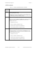
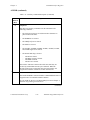
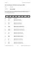
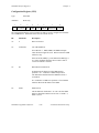
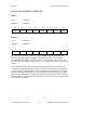
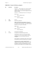
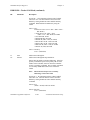
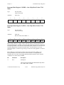
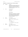
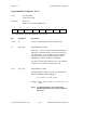
Write the proper value to the Configuration Register (CFG) to establish the condition
for the transfer. Set the TLCHLTE bit to enable the TNT4882 to HALT when an
enabled ISR2, ISR1, or Interrupt Status Register 0 (ISR0) interrupt condition sets.
For GPIB reads, set the IN bit. For GPIB writes—that is, the TNT4882 is the
Talker—clear the IN bit. Set the 16/8N bit to enable the TNT4882 to use both
FIFOs. For GPIB writes, set CCEN to enable the TNT4882 to assert EOI on the last
byte of the transfer.
4.
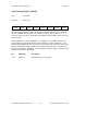
Load the two's complement of the GPIB transfer count into the Count Registers
(CNTs). For GPIB writes, the GPIB transfer count is the number of bytes that will
be sent to the Listener. For GPIB reads, the GPIB transfer count is the maximum
number of bytes that the TNT4882 expects to receive.
5.
ISA pin configuration only: Enable DMA, if needed, by setting the Direct Memory
Access Enable (DMAEN) bit in the Accessory Write Register (ACCWR).
In most ISA systems, you should limit the time DRQ may remain asserted. Set the
TMOE and TIM bits in the CFG register to enable a time limit on the assertion of
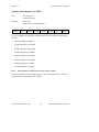
DRQ. Write to the TIMER (offset IE hex) to set the time limit.
6.
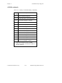
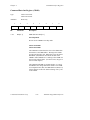
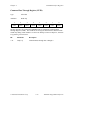
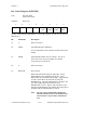
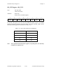
Enable the desired interrupt bits in IMR0, IMR1, and IMR2. For GPIB writes, set
the Error Interrupt Enable (ERR IE) bit in IMR1 to detect no Listener errors. For
GPIB reads, set the End Received Interrupt Enable (END IE) bit to detect whether
the Talker has sent an END byte before the TNT4882 has expected. Write 0 to the
DMA Output Enable (DMAO) bit and the DMA Input Enable (DMAI) bit of IMR2
and set the Timeout Interrupt Enable (TO IE) bit in IMR0, if desired.
7.
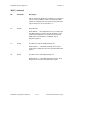
Send the GO command by writing 04 hex to the CMDR.
8.
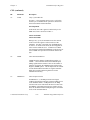
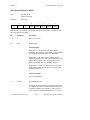
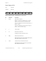
Enable the appropriate interrupts in IMR3, if you are using interrupts. Set the GPIB
Transfer Status Interrupt Enable (DONE IE) bit to interrupt on the normal
completion of a GPIB transfer. Set the TLCINT IE bit to enable interrupts from
ISR0, ISR1, or ISR2. For GPIB writes, set the Not Full FIFO Interrupt Enable
(NFF IE) bit; for GPIB reads, set the Not Empty FIFO Interrupt Enable (NEF IE) bit.
9.
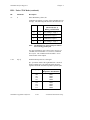
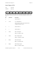
ISA pin configuration only: Enable hardware interrupts by setting the INTEN bit in
the INTR register.
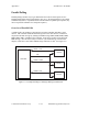
Conducting the Transfer
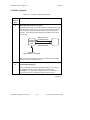
When the transfer has been initialized, data must then be transferred between the system
memory and the GPIB. You must coordinate the data transfer between the system
memory and the FIFOs of the TNT4882; the TNT4882 manages transfers between the
FIFOs and the GPIB. You can transfer data between the system memory and the FIFOs
in two ways: programmed I/O and DMA.
TNT4882 Programmer Reference
4-8
© National Instruments Corp.