1
OP6228 Module
3.1.4.13
Window offset................................................................................................................................................. 23
3.1.4.14
Find trigger...................................................................................................................................................... 23
3.2
OP6228’S CONFIGURATION GUI...................................................................................................................................... 24
3.2.1
Enable ..................................................................................................................................................................... 24
3.2.2
Gain ........................................................................................................................................................................ 24
3.2.3
Offset (V)................................................................................................................................................................. 24
4
THE OP6228 SIMULINK MODEL .................................................................................................................................... 25
4.1
4.2
4.3
5
TD.MDL ........................................................................................................................................................................... 25
CURRENT SENSOR BLOCK ................................................................................................................................................. 25
OPVIRTUALSCOPE ........................................................................................................................................................... 26
FREQUENTLY ASKED QUESTIONS & APPLICATIONS OF THE OP6228............................................................. 30
5.1
5.2
A.
FREQUENTLY ASKED QUESTIONS ..................................................................................................................................... 30
APPLICATIONS OF THE OP6228 MODULE .......................................................................................................................... 34
APPENDIX I - CUSTOMIZING THE GUI ................................................................................................................... 35
A.1.
A.2.
A.3.
A.4.
A.5.
INPUT: ID..................................................................................................................................................................... 35
INPUT: SCOPE ELEMENTS ............................................................................................................................................. 35
INPUT: FILE MANAGEMENT .......................................................................................................................................... 35
OUTPUT: WAVEFORM GRAPH ...................................................................................................................................... 35
REQUIRED CONTROLS................................................................................................................................................... 35
B.
APPENDIX II – BITSTREAM HISTORY..................................................................................................................... 36
C.
APPENDIX III – MEZZANINES AND CONNECTORS ............................................................................................. 37
List of figures
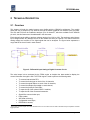
Figure 1 - OP6228 connected with optional OP5511 through an OPAL # 113-0327 cable ................................................... 5
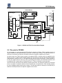
Figure 2 - Differential Input Analog to Digital Converter Circuit ............................................................................................. 8
Figure 3 - OP6228 and FPGA Functional Block Diagram ..................................................................................................... 9
Figure 4 - OP5511’s front panel connectors........................................................................................................................ 12
Figure 5 - J1 25-pin connector (Front view) ........................................................................................................................ 12
Figure 6 - J2 4-pin connector (Front view) .......................................................................................................................... 13
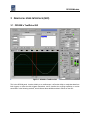
Figure 7 - OP6228’s TestDrive GUI .................................................................................................................................... 15
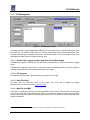
Figure 8 - File Management GUI......................................................................................................................................... 16
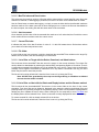
Figure 9 - System Information and Trigger Settings GUI .................................................................................................... 18
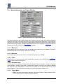
Figure 11 - Scope................................................................................................................................................................ 20
Figure 12 - Display GUI....................................................................................................................................................... 21
Figure 12 - OP6228’s Configuration GUI ............................................................................................................................ 24
Figure 13 - Address bar example ........................................................................................................................................ 30
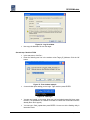
Figure 14 - Log On window ................................................................................................................................................. 31
Figure 15 - Run window example........................................................................................................................................ 31
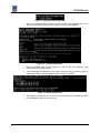
Figure 16 - QNX login ......................................................................................................................................................... 31
Figure 17 - Opening the flashing utility................................................................................................................................ 32
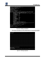
Figure 18 - Flashing utility menu ......................................................................................................................................... 32
Figure 19 - Bitstream selection............................................................................................................................................ 32
Figure 20 - Flashing confirmation........................................................................................................................................ 33
Figure 21 - Flashing completed........................................................................................................................................... 33
Figure 22 - OP6228 with OP5340 on section A .................................................................................................................. 37
Figure 23 - OP6228 with DIN 96-pin connectors labeled .................................................................................................... 37
Current Sensor Module v1.9.doc
Page 3 / 37