1
User’s Manual
FWA-36X0
Network Appliances
1
Copyright Notice
This document is copyrighted, 2002, by Advantech Co., Ltd. All rights are reserved.
Advantech Co., Ltd. reserves the right to make improvements to the products described
in this manual at any time without notice.
No part of this manual may be reproduced, copied, translated or transmitted in any
form or by any means without the prior written permission of the original manufacturer.
Information provided in this manual is intended to be accurate and reliable. However,
the original manufacturer assumes no responsibility for its use, nor for any
infringements upon the rights of third parties that may result from its use.
Acknowledgements
z
z
z
z
AWARD is a trademark of AWARD Software, Inc.
IBM and PC are trademarks of International Business Machines Corporation
Intel, Pentium III and Tualatin are trademarks of Intel Corporation
Windows NT 4.0 and Windows 2000 are trademarks of Microsoft Corporation
All other product names or trademarks are properties of their respective owners.
CE Notification
FWA-3600, FWA-3660 and FWA-36XXXXX developed by Advantech Co., Ltd. have
passed the CE test for environment specifications when shielded cables are used for
external wiring. We recommend the use of shielded cables.
2
Product Warranty
Advantech warrants to you, the original purchaser, that each of its products will be free
from defects in materials and workmanship for one year from the date of purchase.
This warranty does not apply to any products which have been repaired or altered by
persons other than repair personnel authorized by Advantech, or which have been
subject to misuse, abuse, accident or improper installation. Advantech assumes no
liability under the terms of this warranty as a consequence of such events.
Because of Advantech’s high quality-control standards and rigorous testing, most of our
customers never need to use our repair service. If an Advantech product is defective, it
will be repaired or replaced at no charge during the warranty period. For
out-of-warranty repairs, you will be billed according to the cost of replacement
materials, service time and freight. Please consult your dealer for more details.
If you think you have a defective product, follow these steps:
1. Collect all the information about the problem encountered. For example, CPU speed,
Advantech products used, other hardware and software used, etc. Note anything
abnormal and list any on-screen messages you get when the problem occurs.
2. Call your dealer and describe the problem. Please have your manual, product, and any
helpful information readily available.
3. If your product is diagnosed as defective, obtain an RMA (return merchandise
authorization) number from your dealer. This allows us to process your return more
quickly.
4. Carefully pack the defective product, a fully completed Repair and Replacement
Order Card and a photocopy proof of purchase date (such as your sales receipt) in a
shippable container. A product returned without proof of the purchase date is not
eligible for warranty service.
5. Write the RMA number visibly on the outside of the package and ship it prepaid to
your dealer.
3
Packing List
You should find the items listed below in the server package. If anything is missing or
damaged, please consult with your vendor for resolution.
z
z
z
z
z
z
1 CPU heat sink
1 Console cable
1 HDD flat cable
4 Screw Sinks for HDD drive
1 CD Title-Driver & Manual
1 Warrant Card
Technical Support and Sales Assistance
If you have any technical questions about the FWA-3600 series products, please visit
our support website at http://www.advantech.com.tw/support
For more information about Advantech products and sales information, please visit:
http://www.advantech.com.
4
Table of Contents
CHAPTER 1 INTRODUCTION.................................................. 7
1.1 About the FWA-3600 Series..............................................................................7
1.2 Specification ......................................................................................................8
1.2.1 FWA-3660 Specification
8
1.2.2 FWA-3600 Specification
9
1.3 The Motherboard of FWA-3600 Series ..........................................................10
1.3.1 Component Side
10
1.3.2 Solder Side
11
1.3.3 Pin Definition of Motherboard (POD-9578) Connectors
12
1.4 The mechanism of FWA-3600 Series.............................................................20
1.5 Operating Systems..........................................................................................24
CHAPTER 2 INSTALLATION AND CONFIGURATION ......... 26
2.1 Install CPU and heat-sink ...............................................................................26
2.2 Console Redirection........................................................................................29
CHAPTER 3 DRIVER INSTALLATION................................... 32
3.1 Install VGA Driver ............................................................................................34
3.1.1 Driver Installation for WIN 2000
34
3.1.2 Driver Installation for Linux
35
3.2 Install LAN Driver ............................................................................................38
3.2.1 Driver Installation for WIN 2000/XP
38
3.2.2 Driver Installation for Linux
39
CHAPTER 4 WATCHDOG TIMER AND LAN BYPASS......... 41
4.1 Watchdog Timer Programming ......................................................................41
4.2 LAN Bypass Function .....................................................................................42
CHAPTER 5 LCM.................................................................... 45
5.1 General Information ........................................................................................45
5.1.1 - Introduction
45
5.2 LCM-100S Hardware Installation....................................................................46
5.3 LCM-100S Demo Tool........................................................................................1
5.4 LCM-100S Operation Examples .......................................................................1
5.5 Operation Procedure.........................................................................................2
5.6 LCM-100S Command.........................................................................................3
CHAPTER 6 BIOS SETUP........................................................ 6
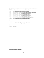
6.1Function Keys.....................................................................................................6
5
6.2 Main Menu ..........................................................................................................7
6.2.1 Standard CMOS Features
8
6.2.2 Advanced BIOS Features
12
6.2.3 Advanced Chipset Features
15
6.2.4 Integrated Peripherals
16
6.2.5 Power Management Setup
19
6.2.6 PnP/PCI Configurations
24
6.2.7 PC Health Status
26
6.2.8 Frequency/Voltage Control
27
6.2.9 Load Optimized Defaults
28
6.2.10 Set Password
29
6.2.11 Save & Exit Setup
30
6.2.12 Exit without Saving
31
CHAPTER 7 LAN EXPANSION.............................................. 32
6
Chapter 1 Introduction
1.1 About the FWA-3600 Series
A Rackmount powerful Network Appliance, the FWA-36X0 is specifically designed for
Internet secure connectivity. It is and is suitable for SOHO (Small Office, Home Office),
SMB (Small Medium Business), and ROBO (Remote Office, Branch Office) segments.
Designed within the Intel® Pentium/ Celeron processor, it has high performance that can
meet the requirement needed of firewall appliance. The system supports a Compact Flash
used in installing OS and Firewall/VPN application, which totally avoids the service
disruption caused by hard disk’s mechanical/magnetic failures. In addition, the FWA-36X0
can support system memory up to 512 MB SDRAM. Both the Compact Flash card and
SDRAM can be accessed and replaced for software upgrade through an easily removable
cover. Designed with the Plug-and-Serve concept in mind, the FWA-36X0 offers Maximum
10/100 Mbps auto-sensing Fast Ethernet ports in the front panel for WAN1, WAN2, LAN,
and DMZ connections. There are eight LED indicators on the front panel display that
monitors LAN activities and LAN link speed (10 M or 100 M bit per second). Also on the
front panel for easy access is a 9-pin, RS-232 serial port for local system management,
maintenance, and diagnostics. A LCD module can be programmed to show system messages.
The FWA-36X0 reserves a place for an optional 3.5” IDE HDD, which can be installed for
storing event log and user data. It meets FCC and CE compliance. For some special network
appliance applications, it is necessary to require the LAN bypass function. FWA-3600 series
reserves manufacture option for the 2 LAN ports. Meanwhile, FWA-3600 series is equipped
with a watchdog timer that resets the CPU or generates an interrupt if processing comes to a
standstill for whatever reason. This feature ensures system reliability in industrial standalone,
or unmanned, environments. The detail will be discussed later. The console re-direction
function of FWA-3600 series allows users to set CMOS parameter via consol port. The
FWA-3600 series supports Windows 2000/XP and Linux OS. Here, we also provide a
hardened Linux OS in driver CD. The hardened Linux is useful, but it is not guaranteed
because each customer has different requirement.
7
1.2 Specification
1.2.1 FWA-3660 Specification
Process
Memory
Ethernet
Drive Bay
Cooling
Management
Miscellaneous
Adapter Power
Requirement
Environment
Physical
CPU
Max. Speed
L2 Cache
Chipset
BIOS
Technology
Max. Capacity
Interface
Controller
Connector
3.5”HDD
Fan
Console
Control
CompactFlash
Socket
LCD module
Input
Output
Intel® Pentium III/ Celeron
1.26GHz/1.2GHz
512KB, 256KB/256KB, 128 KB
Intel 815E
Award 2 Mb Flash
PC-133/100 SDRAM
512 MB
10/100 Base-TX
Intel 82559ER x 3, ICH2 x 1
RJ-45 x 4
1
2 (15 CFM/each)
RS-232 x1
Power switch
1
Temperature
Humidity
Dimension
(W x H x D)
Weight
0 ~ 40 °C (32 ~ 104 °F)
1
AT PS, AC 90 ~ 264 V full range @ 47 ~ 63 Hz
180 W (w/PFC)
Operating
Non-Operating
-20 ~ 75 °C (-4 ~ 167 °F)
5 ~ 85 %@ 40 °C (104 °F) 5 ~ 95 %
426 x 44.4 x 280 mm cube
4.5Kg
8
1.2.2 FWA-3600 Specification
Process
Memory
Ethernet
Drive Bay
Cooling
Management
Miscellaneous
Adapter Power
Requirement
Environment
Physical
CPU
Max. Speed
L2 Cache
Chipset
BIOS
Technology
Max. Capacity
Interface
Controller
Connector
3.5”HDD
Fan
Console
Control
CompactFlash
Socket
LCD module
Input
Output
Intel® Pentium III/ Celeron
1.26GHz/1.2GHz
512KB, 256KB/256KB, 128 KB
Intel 815E
Award 2 Mb Flash
PC-133/100 SDRAM
512 MB
10/100 Base-TX
Intel 82559ER x 3
RJ-45 x 3
1
2 (15 CFM/each)
RS-232 x1
Power switch
1
Temperature
Humidity
Dimension
(W x H x D)
Weight
0 ~ 40 °C (32 ~ 104 °F)
1
AT PS, AC 90 ~ 264 V full range @ 47 ~ 63 Hz
180 W (w/PFC)
Operating
Non-Operating
-20 ~ 75 °C (-4 ~ 167 °F)
5 ~ 85 %@ 40 °C (104 °F) 5 ~ 95 %
426 x 44.4 x 280 mm cube
4.5Kg
9
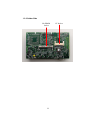
1.3 The Motherboard of FWA-3600 Series
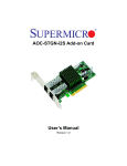
1.3.1 Component Side
10 11
1
2
3
12
4
5
13
6
7
14
8
15
9
1: CN2 & CN3- PCI BUS pin header for LAN expansion
2: CN5- Provide 8 GPIO
3: keyboard and mouse connector
4: COM1- Console Port
5: COM2- pin header
6: RJ45 LAN4 connector (ICH2)
7: RJ45 LAN3 connector (Intel 82559ER)
8: RJ45 LAN2 connector (Intel 82559ER)
9: RJ45 LAN1 connector (Intel 82559ER)
10: PCI slot
11: IDE connector (44pin)
12: Relay for LAN Bypass- LAN3 and LAN4 (manufacture option)
13: VGA pin header
14: FC-PGA370 socket for FC-PGA and FC-PGA2 CPU only
15: Power Connector
10
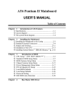
1.3.2 Solder Side
SO-DIMM
Socket
11
CF Socket
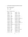
1.3.3 Pin Definition of Motherboard (POD-9578) Connectors
CN1 System FAN-2 connector
Pin-1 => FAN plus signal
Pin-2 => +12V
Pin-3 => GND
CN2,CN3 PCI signal connector
CN3 Pin-1 => NC
CN3 Pin-2 => NC
CN3 Pin-3 => NC
CN3 Pin-4 => +12V
CN3 Pin-5 => GND
CN3 Pin-6 => TMS
CN3 Pin-7 => NC
CN3 Pin-8 => TDI
CN3 Pin-9 => +5V
CN3 Pin-10 => +5V
CN3 Pin-11 => +5V
CN3 Pin-12 => INTA#
CN3 Pin-13 => INTB#
CN3 Pin-14 => INTC#
CN3 Pin-15 => INTD#
CN3 Pin-16 => +5V
CN3 Pin-17 => NC
CN3 Pin-18 => GNTE#
CN3 Pin-19 => REQE#
CN3 Pin-20 => VIO (Select by J1)
CN3 Pin-21 => SUS 3.3V
CN3 Pin-22 => #PGNT5
CN3 Pin-23 => GND
CN3 Pin-24 => GND
CN3 Pin-25 => GND
CN3 Pin-26 => GND
CN3 Pin-27 => WOL2
CN3 Pin-28 => #PREQ5
CN3 Pin-29 => GND
CN3 Pin-30 => PCIRST
CN3 Pin-31 => PCICLK
CN3 Pin-32 => VIO (Select by J1)
CN3 Pin-33 => GND
CN3 Pin-34 => GNTD#
CN3 Pin-35 => REQD#
CN3 Pin-36 => GND
CN3 Pin-37 => VIO (Select by J1) CN3 Pin-38 => SUS 5V
CN3 Pin-39 => AD31
CN3 Pin-40 => AD30
CN3 Pin-41 => AD29
CN3 Pin-42 => +3.3V
CN3 Pin-43 => GND
CN3 Pin-44 => AD28
CN3 Pin-45 => AD27
CN3 Pin-46 => AD26
CN3 Pin-47 => AD25
CN3 Pin-48 => GND
CN3 Pin-49 => +3.3V
CN3 Pin-50 => AD24
CN3 Pin-51 => C/BE3#
CN3 Pin-52 => IDSEL (AD28)
CN3 Pin-53 => AD23
CN3 Pin-54 => +3.3V
CN3 Pin-55 => GND
CN3 Pin-56 => AD22
CN3 Pin-57 => AD21
CN3 Pin-58 => AD20
CN3 Pin-59 => AD19
CN3 Pin-60 => GND
12
CN2 Pin-1 => +3.3V
CN2 Pin-2 => AD18
CN2 Pin-3 => AD17
CN2 Pin-4 => AD16
CN2 Pin-5 => C/BE2#
CN2 Pin-6 => +3.3V
CN2 Pin-7 => GND
CN2 Pin-8 => FRAME#
CN2 Pin-9 => IRDY#
CN2 Pin-10 => GND
CN2 Pin-11 => +3.3V
CN2 Pin-12 => TRDY#
CN2 Pin-13 => DEVSEL#
CN2 Pin-14 => GND
CN2 Pin-15 => GND
CN2 Pin-16 => STOP#
CN2 Pin-17 => PLOCK#
CN2 Pin-18 => +3.3V
CN2 Pin-19 => PERR#
CN2 Pin-20 => SDONE
CN2 Pin-21 => +3.3V
CN2 Pin-22 => SBO
CN2 Pin-23 => SERR#
CN2 Pin-24 => GND
CN2 Pin-25 => +3.3V
CN2 Pin-26 => PAR
CN2 Pin-27 => C/BE1#
CN2 Pin-28 => AD15
CN2 Pin-29 => AD14
CN2 Pin-30 => +3.3V
CN2 Pin-31 => GND
CN2 Pin-32 => AD13
CN2 Pin-33 => AD12
CN2 Pin-34 => AD11
CN2 Pin-35 => AD10
CN2 Pin-36 => GND
CN2 Pin-37 => GND
CN2 Pin-38 => AD9
CN2 Pin-39 => AD8
CN2 Pin-40 => C/BE0#
CN2 Pin-41 => AD7
CN2 Pin-42 => +3.3V
CN2 Pin-43 => +3.3V
CN2 Pin-44 => AD6
CN2 Pin-45 => AD5
CN2 Pin-46 => AD4
CN2 Pin-47 => AD3
CN2 Pin-48 => GND
CN2 Pin-49 => GND
CN2 Pin-50 => AD2
CN2 Pin-51 => AD1
CN2 Pin-52 => AD0
CN2 Pin-53 => VIO(Select by J1) CN2 Pin-54 => VIO (Select by J1)
CN2 Pin-55 => ACK64#
CN2 Pin-56 => REQ64#
CN2 Pin-57 => +5V
CN2 Pin-58 => +5V
CN2 Pin-59 => +5V
CN2 Pin-60 => +5V
CN4 Power & HDD LED connector
Pin-1 => HDD LED+
Pin-2 => HDD LEDPin-3 => Power LED+
Pin-4 => Power LED13
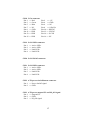
CN5 Digital I/O connector
Pin-1 => IO0
Pin-2 => IO1
Pin-3 => IO2
Pin-4 => IO3
Pin-5 => IO4
Pin-6 => IO5
Pin-7 => IO6
Pin-8 => IO7
Pin-9 => GND
Pin-10 => GND
CN6 Reset button connector
Pin-1 => GND
Pin-2 => Reset signal
CN7 FAN failure LED connector
Pin-1 => FAN fail LED+
Pin-2 => FAN fail LED-
CN8 IDE connector
Pin-1 => IDE Reset
Pin-3 => D7
Pin-5 => D6
Pin-7 => D5
Pin-9 => D4
Pin-11 => D3
Pin-13 => D2
Pin-15 => D1
Pin-17 => D0
Pin-19 => GND
Pin-21 => DRQ
Pin-23 => IOW
Pin-25 => IOR
Pin-27 => IORDY
Pin-29 => DACK
Pin-31 => IRQ14
Pin-33 => A1
Pin-35 => A0
Pin-37 => CS1#
Pin-39 => Active
Pin-2 => GND
Pin-4 => D8
Pin-6 => D9
Pin-8 => D10
Pin-10 => D11
Pin-12 => D12
Pin-14 => D13
Pin-16 => D14
Pin-18 => D15
Pin-20 => NC
Pin-22 => GND
Pin-24 => GND
Pin-26 => GND
Pin-28 => Cable Select
Pin-30 => GND
Pin-32 => NC
Pin-34 => Reserved
Pin-36 => A2
Pin-38 => CS3#
Pin-40 => GND
14
Pin-41 => +5V
Pin-43 => GND
Pin-42 => +5V
Pin-44 => NC
CN9 Print port connector
Pin-1 => STB#
Pin-2 => AFD#
Pin-3 => D0
Pin-4 => ERR#
Pin-5 => D1
Pin-6 => INIT#
Pin-7 => D2
Pin-8 => SLIN
Pin-9 => D3
Pin-10 => GND
Pin-11 => D4
Pin-12 => GND
Pin-13 => D5
Pin-14 => GND
Pin-15 => D6
Pin-16 => GND
Pin-17 => D7
Pin-18 => GND
Pin-19 => ACK#
Pin-20 => GND
Pin-21 => BUSY
Pin-22 => GND
Pin-23 => PE
Pin-24 => GND
Pin-25 => SLCT
Pin-26 => GND
CN10
Pin-1
Pin-2
Pin-3
System FAN-1 connector
=> FAN plus signal
=> +12V
=> GND
CN11
Pin-1
Pin-2
Pin-3
Pin-4
Pin-5
Pin-6
Pin-7
Pin-8
Keyboard & PS2 Mouse connector
=> GND
=> +5V
=> MSDATA signal
=> MSCLK signal
=> GND
=> +5V
=> KBDATA
=> KBCLK
15
CN12
Pin-1
Pin-3
Pin-5
Pin-7
Pin-9
CN13
Pin-1
Pin-2
Pin-3
Pin-4
Pin-5
Pin-6
Pin-7
Pin-8
Pin-9
USB connector
=> +5V
=> USB0=> USB0+
=> USB_GND
=> GND
Pin-2 => +5V
Pin-4 => USB1Pin-6 => USB1+
Pin-8 => USB_GND
Pin-10 => NC
COM1 D-SUB connector
=> DCD
=> RXD
=> TXD
=> DTR
=> GND
=> DSR
=> RTS
=> CTS
=> RI
CN14 Reserved
CN15
Pin-1
Pin-2
Pin-3
Pin-4
LAN4 LED connector
=> Active LED+
=> Active LED=> Link LED+
=> Link LED-
CN16
Pin-1
Pin-3
Pin-5
Pin-7
Pin-9
COM2 connector
=> DCD
Pin-2 => DSR
=> RXD
Pin-4 => RTS
=> TXD
Pin-6 => CTS
=> DTR
Pin-8 => RI
=> GND
Pin-10 => NC
CN17 LAN4 RJ-45 connector
16
CN18 VGA connector
Pin-1 => Red
Pin-3 => Green
Pin-5 => Blue
Pin-7 => NC
Pin-9 => GND
Pin-11 => GND
Pin-13 => GND
Pin-15 => GND
CN19
Pin-1
Pin-2
Pin-3
Pin-4
Pin-2 => +5V
Pin-4 => GND
Pin-6 => NC
Pin-8 => S-DATA
Pin-10 => HSYNC
Pin-12 => VSYNC
Pin-14 => S-CLK
Pin-16 => NC
LAN3 LED connector
=> Active LED+
=> Active LED=> Link LED+
=> Link LED-
CN20 LAN3 RJ-45 connector
CN21
Pin-1
Pin-2
Pin-3
Pin-4
LAN2 LED connector
=> Active LED+
=> Active LED=> Link LED+
=> Link LED-
CN22 ATX power On/Off button connector
Pin-1 => Power On/Off signal
Pin-2 => GND
CN23
Pin-1
Pin-2
Pin-3
ATX power suspend 5V and PS_ON signal
=> Suspend 5V
=> GND
=> PS_ON signal
17
CN24 LAN2 RJ-45 connector
CN25
Pin-1
Pin-2
Pin-3
CPU FAN-2 connector
=> FAN plus signal
=> +12V
=> GND
CN26 LAN1 RJ-45 connector
CN27
Pin-1
Pin-2
Pin-3
Pin-4
LAN1 LED connector
=> Active LED+
=> Active LED=> Link LED+
=> Link LED-
CN29
Pin-1
Pin-2
Pin-3
Pin-4
Pin-5
Pin-6
Pin-7
EBX Power connector
=> +5V
=> GND
=> GND
=> NC
=> NC
=> GND
=> +5V
J1 PCI VIO select
Pin-1 => +5V
Pin-2 => VIO
Pin-3 => +3.3V
Pin-1,2 closed => PCI VIO select +5V
Pin-2,3 closed => PCI VIO select +3.3V
18
J2
L3, L4 by pass control
--------------------------------------------------------------------------------Pins Auto Detect* by GPIO
Always enable
----------------------------------------------------------------------------------1-3 Closed
Closed
open
3-5 NA
NA
open
2-4 Closed
NA
NA
4-6 NA
Closed
NA
* Default setting
J3 LAN3, LAN4 Bypass signal select (When J2 Pin-1,2 closed)
Pin-1,2 closed => When Power on , Relay auto on
Pin-2,3 closed => Relay On/Off control by ICH GPO23
J4 CMOS Clear jumper
Pin-1,2 closed => Normal
Pin-2,3 closed => Clear CMOS data
J5 Firmware Hub Lock jumper
Pin-1,2 closed => Firmware Hub write enable
Pin-1,2 open => Firmware Hub read only
PCI Bus difference:
A9 => #PGNTE
A11 => #PGNT5
A14 => #PREQ5
A19 => Suspend 5V
B10 => #PREQE
B11 => Suspend 3.3V
B14 => WOL1
(Normal is RSV)
(Normal is RSV)
(Normal is RSV)
(Normal is RSV)
(Normal is RSV)
(Normal is #PRSNT2)
(Normal is RSV)
19
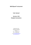
1.4 The mechanism of FWA-3600 Series
The FWA-3600 series has an internal Compact Flash card. The system only
supports PIII/Celeron processor (FC-PGA/FC-PGA2) with one SO-DIMM
socket, which supports up to 512MB PC-133 SDRAM SO-DIMM. The system
comes with an external AC adapter.
1
2
34
5
6
78
1: LCD Module (LCM-100S)
2: Console port
3: LAN4 Connector (RJ-45)
4: LAN3 Connector (RJ-45)
5: LAN2 Connector (RJ-45)
6: LAN1 Connector (RJ-45)
7: LAN Link LED
8: LAN Activity LED
Cross table for LAN port definition
LAN4
LAN3
LAN2
Eth0
Eth3
Eth2
N/A
DMZ
LAN
FWA-3600
DMZ
LAN
WAN1
FWA-3660
20
LAN1
Eth1
WAN
WAN2
Firewall/VPN LAN Port Definition
DMZ Port
The DMZ port connector is RJ-45 and supports 10/100BaseTX Ethernet
(10 Mbps/100 Mbps on a twisted pair cable). This port connects
non-secured/ untrusted devices.
LAN Port
The LAN port connector is RJ-45 and supports 10/100BaseTX Ethernet
(10 Mbps/100 Mbps on a twisted pair cable). This port connects to
secured/trusted devices.
WAN Port
The WAN port connector is RJ-45 and supports 10/100BaseTX Ethernet
(10 Mbps/100 Mbps on a twisted pair cable). This port connects to the
external network of Internet.
Console Port
The console port supports a data terminal equipment (DTE) interface
(cable included) with 8 data bits, no parity, and 1 stop bit, the default
speed is 38400 bps.
DMZ LED
When the cable is connected to the DMZ, the LED is orange. When the
FWA-3600 series receives the data, the above LED flashes green.
LAN LED
When the cable is connected to the LAN, the LED is orange. When the
FWA-3600 series receives data, the above LED flashes green.
WAN LED
When the cable is connected to the WAN, the LED is orange. When the
FWA-3600 series receives data, the above LED flashes green.
Power LED (PWR)
The PWR LED is green under normal conditions.
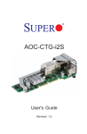
21
1
2
3
4
1: Power Supply
2: 3.5” HDD mounting bracket
3: System FANs
4: CPU socket
22
1
2
3
1: Remove the cover to order to install Compact Flash card and SO-DIMM
2: Compact Flash installed (Optional)
3: SO-DIMM SDRAM installed (Optional)
23
1.5 Operating Systems
The FWA-3600 series support Windows 2000, Windows XP and Linux OS.
There is a hardened Linux OS in driver CD. Please take a look at driver CD for
more detail information. Please remember that the hardened Linux OS is not
guaranteed to meet with your requirement. In order to let users easy to develop
their own software on the platform, it is recommended that users can purchase
the following optional items:
Optional Accessory
No
1
2
3
4
5
6
Item Description
Power cable
USB cable
parallel cable
VGA port cable
keyboard/ PS2 mouse cable
Flat Cable 44P 50cm:
44P/40P/40P(Idiot-Proof)
24
Part number
1703080101
1703100260
1700260250
1701160101
1700060200
1701440500
25
Chapter 2 Installation and Configuration
2.1 Install CPU and heat-sink
Raise the retaining lever of CPU socket to a position perpendicular to the socket up.
Orient the CPU to the socket correctly so that the pins match the receptacles. Insert
the CPU in the socket so that the pins fully insert.
26
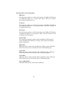
After a CPU has been installed, you will need to install the proper cooling device
for the CPU. The platform comes with one high efficiency heat-sink that sits on the
top of an installed CPU and clip onto the CPU socket. Before heat-sink installation,
please take out the heat-spread glue as below. Paint the heat-spread glue on the
CPU die evenly as previous picture.
Take out the heat-spread glue.
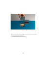
Place the clip to hold the protrusion on the side of CPU socket.
27
Place the clip to hold the protrusion on another side of CPU socket. Use a screw
driver for help to Press the spring clip over the protrusion so that it snaps in place.
Note: Without thermal glue, system will overheat.
28
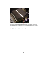
2.2 Console Redirection
Use the null-modem cable (console cable) to connect the client’s COM1 port to
the console port of FWA-600 series. The other end of cable connects with
another PC running Windows 98/2000/XP.
To set up a Windows OS system:
1.
Run a console client management program such as HyperTerminal
6.X to configure the console port connection.
2.
HyperTerminal 6.X is applied in the following example:
29
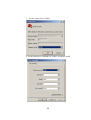
3. Set the connection to COM1.
4. Set the baud rate to 38400bps for COM1. It emulates ANSI.
30
Port settings to be configured:
Bits per second
Data bits
Parity
Stop bits
Flow control
38400 (bps)
8
None
1
None
The screen shows Client performs Hyperterminal in remote site.
31
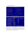
Chapter 3 Driver Installation
The FWA-3600 series supports several Operating Systems including
Microsoft Windows 2000/XP and Linux 6.x/7.x.
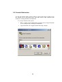
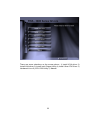
In the driver bank CD disc, there are some options as below when running
“Setup” or CD auto-run.
32
There are some selections on the screen above: 1) Install VGA driver 2)
Install LAN driver 3) Install Intel Chipset Utility 4) Install Ultra ATA Driver 5)
Hardened Linux 6) LCD-100S Utility 7) Manual
33
3.1 Install VGA Driver
Since the platform doesn’t provide external VGA port, it is recommended
to turn off the VGA such that the system performance will be increased.
Click “Install VGA driver” selection. There is one folder- “Win2000”
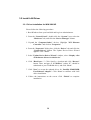
3.1.1 Driver Installation for WIN 2000
1. Open “Win2000” folder.
2. Excute”setup.exe"
3. Restart your computer when the installation has completed.
34
3.1.2 Driver Installation for Linux
Intel i810 / i815 Graphic Driver Installation Notes
* A. Download and read the Intel Graphic Release Notes
(http://support.intel.com)
B. Download two RPM files from support.intel.com
I810Gtt-0.2-4.src.rpm and XFCom_i810-1.2-3.i386.rpm
* Prerequisities
a. XFree86 3.3.6
b. Kernel version 2.2.x or higher with sources
c. glibc 2.1 or higher
d. gcc
35
** RedHat 6.2 includes all of them **
* The following steps are done in Redhat 6.2
A. Compile and install the kernel module
mkdir /810
# copy two rpm files (I810Gtt-0.2-4.src.rpm
XFCom_i810-1.2-3.i386.rpm) to /810
cd /810
rpm --recompile I810Gtt-0.2-4.src.rpm
A. Verify that the module has been correctly loaded
cat /proc/modules | grep agpgart
# A line starting with "agpgart" should be produced
B. XFCom i810 Server Installation
(1) Verify the XFree86 version
/bin/sh -c 'X -version 2>&1 |head -2'
# the version has to be 3.3.6
(2) Install the XFXom_i810 server
cd /810
rpm -Uvh XFCom_i810-1.2-3.i386.rpm
36
C. Use Xconfigurator to setup the XF86Config file
su -c Xconfigrator
D. Start X windows
startx
37
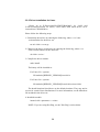
3.2 Install LAN Driver
3.2.1 Driver Installation for WIN 2000/XP
Please follow the following procedure:
1. Boot Windows from your hard disk and log in as Administrator.
2. From the “Control Panel”, double-click the “System” icon, select the
“Hardware” tab, and click the “Device Manager” button.
3. Expand the “Computer\Other” devices. Highlight "PCI Ethernet
Controller" and click on "Properties".
4. From the “Properties” dialog box, click the “Driver” tab and click the
“Update Driver” button. The Update Device Driver Wizard
appears. Click “Next”.
5. In the "Update Device Driver Wizard" window, select “Display a list
of the known drivers for this device”.
6. Click “Hard have…”. Click Specify a location and click “Browse”
button. Then, navigate to “F:\82559er” (where “F” should be
substituted as your CD-ROM drive), and click “Next”.
7. Click “Next” to accept the updated driver for “Intel(R) GD82559ER
Fast Ethernet Adapter”. Click “Next” to continue with LAN
driver installation.
8. Follow the instructions on the screen. Click “Finish” to complete
installation.
38
3.2.2 Driver Installation for Linux
Please go to E:\Driver\lan\562\LINUX\Red-hat62 for LAN1 and
E:\Driver\lan\559er\linux for LAN2, LAN3 and LAN4 when driver CD is
inserted into CD-ROM drive.
Please follow the following steps:
1. Untar/unzip the archive by entering the following, where x.x.x is the
version number for the driver tar:
tar xfz e100-x.x.x.tar.gz
2. Change to the driver src directory by entering the following, where x.x.x
is the version number for the driver tar:
cd e100-x.x.x/src/
3. Compile the driver module:
make install
The binary will be installed as:
For Linux 2.2.x systems:
/lib/modules/[KERNEL_VERSION]/net/e100.o
For Linux 2.4.x systems:
/lib/modules/[KERNEL_VERSION]/kernel/drivers/net/e100.o
The install locations listed above are the default locations. They may not be
correct for certain Linux distributions. For more information, see the ldistrib.txt
file included in the driver tar.
4. Install the module:
insmod e100 <parameter>=<value>
NOTE: If you are using Hot Plug, see the "Hot Plug" section below.
39
5. Assign an IP address to the interface by entering the following, where <x>
is interface number:
ifconfig ethx <IP_address>
6. Verify that the interface works. Enter the following, where <IP_address>
is the IP address for another machine on the same subnet as the interface
that is being tested:
ping <IP_address>
NOTE: In order to see link messages and other Intel driver information on
your console, you must set the dmesg level up to six. This can be done
by entering the following on the command line:
dmesg -n 6
If you wish to see all messages issued by the driver, including debug
messages, set the dmesg level to seven.
40
Chapter 4 Watchdog Timer and LAN Bypass
4.1 Watchdog Timer Programming
The FWA-3600 series is equipped with a watchdog timer that resets the CPU
or generates an interrupt if processing comes to a standstill for whatever
reason. This feature ensures system reliability in industrial standalone, or
unmanned, environments.
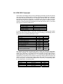
In order to program the watchdog timer, you must write a program which
writes I/O port address 443 (hex). The output data is a value of time interval.
The value range is from 01(hex) to 3E(hex), and the related time interval is 1
sec. to 62 sec.
Data
01
02
03
04
.
.
.
3E
Time Interval
1 sec.
2 sec.
3 sec.
4 sec.
62 sec.
After data entry, your program must refresh the watchdog timer by rewriting
the I/O port 443 (hex) while simultaneously setting it. When you want to
disable the watchdog timer, your program should
read I/O port 443 (hex).
41
The following example shows how you might program the watchdog timer in
BASIC:
10
20
30
40
50
60
70
80
1000
.
.
.
1070
2000
.
.
.
2090
REM Watchdog timer example program
OUT &H443, data REM Start and restart the watchdog
GOSUB 1000 REM Your application task #1
OUT &H443, data REM Reset the timer
GOSUB 2000 REM Your application task #2
OUT &H443, data REM Reset the timer
X=INP (&H443) REM Disable the watchdog timer
END
REM Subroutine #1, you application task
RETURN
REM Subroutine #2, you application task
RETURN
4.2 LAN Bypass Function
42
The motherboard for FWA-3600 series is POD-9578. The POD-9578
reserves LAN Bypass hardware. That means the standard platform does not
own the function. It belongs to customized project.
Here, POD-9578 uses ICH2 GPO23 to control relay ON/OFF for LAN bypass
function. Customers can set default LAN Bypass or normal in CMOS
parameter. After BIOS booting and OS booting, customers can set LAN
BYPASS status via programming ICH2 GPO23. Please read ICH2 datasheet
put in driver CD to design your AP (Application Software). The LAN Bypass
operation procedure is described as the following for reference only. The
procedure should be inserted into customer’s AP.
J2
L3, L4 by pass control
--------------------------------------------------------------------------------Pins Auto Detect* by GPIO
Always enable
----------------------------------------------------------------------------------1-3 Closed
Closed
open
3-5 NA
NA
open
2-4 Closed
NA
NA
4-6 NA
Closed
NA
* Default setting
LAN BYPASS FUNCTION OPERATION PROCEDURE
START
43
LAN3 bypass LAN4
(Hardware Default via CMOS
setting)
Power ON
BIOS Booting
OS Booting
Customer AP Enable
Reset System
by Watchdog
AP set LAN3 and LAN4 isolation
AP Enable watchdog Timer and set
Timer
No
No
Set Watchdog
Timer?
Yes
Set Watchdog Timer
44
Yes
Time out
Chapter 5 LCM
5.1 General Information
5.1.1 - Introduction
The major purpose of this module is to provide an easier man-machine interface for
those computing systems in which applications friendly operation is a “must”. In
traditional computing system design, proprietary keypad and LCD display interfaces
are implemented and these interfaces are usually different from system to system.
The design goals of this interface are:
A. A single interface fore both LCD display and keypad is required.
B. This interface should be available in every computing system
C. The communication implementation should be OS independent.
Our solution is to use “Serial port” as the interface for both LCD display and keypad. A
simple protocol is further defined so that applications can directly communicate with
this module no matter what the operating system is.
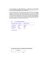
There are only two connectors in this module, as shown in Fig 5.1; power connector
and serial port connector.
Power connector
Serial port
connector
Figure 5.1
The power source into this module is 5volt only. There are only three pins being used
in the serial port interface:
Pin 2: TxD
Pin 3: RxD
Pin 5: Ground
5.1.2 In another word, this serial port is defined as DCE, therefore, we can use
straight-through cable to connect it to serial port of most computers because
they are defined as DTE.
45
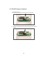
5.2 LCM-100S Hardware Installation
The installation steps are:
A. Connect the power cable to the power connector of this module.
Figure 5.2
B. Connect the straight-through cable between serial port of this module and
computer.
Figure 5.3
46
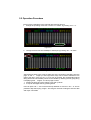
5.3 LCM-100S Demo Tool
It is a tool for DOS and can be run in Windows environment as well. There are two
areas in this Demo/testing tool. The upper area is for editing / sending command /
data, as figure 5.4 shows. The upper area consists of a couple of pages; every page
can store up to ten command / data strings. The first byte of every command / data
string specifies the length of this string. The second byte and the rest are the content
to be sent out and are entered in Hexadecimal format. Detailed function of the tool will
be shown after pressing “ALT + F1” keys. To exit the demo tool program, “ALT+ X”
can be pressed.
Figure 5.4
1
5.4 LCM-100S Operation Examples
There pages of examples are stored as default data of this demo tool. The stored
contents are as following:
A. The first page (page 0)
F1: ASCII code of string “CD”
F2: Command string to shift the string to right hand side for 3 characters
F3: Command string to shift the string to right hand side for 3 characters.
F4: Command string to shift the string to right hand side for 3 characters.
F5: Command string to request the key-pad status. A response command will be
showed after this request command.
F6: Command string to shift the string to left hand side for 3 characters.
F7: Command to position the cursor to the bottom line, shift the string to right hand
side for 2 characters and ASCII code of string "abcd”.
F8: command string to shift the string to left hand side for 3 characters.
F9: Command string to request the key-pad status.
F10: Command to clear screen.
B. The first page (page 1)
F1: ASCII code of character “A”.
F2: ASCII code of character “L”.
F3: ASCII code of character "b”.
F4: Command string to request the key-pad status. A response command will be
shown after this request command.
F5: Clear screen command.
F6: Command to position the cursor at the beginning of the second column.
F7: Command to position the cursor at the beginning of the first column.
F8: ASCII code of string “ABCDEFGHIJ”
F9: Command to scroll the displayed string to left hand side for one character.
F10: Command to scroll the displayed string to right hand side for one character.
C. The second page (page 2)
F1: Command to position the cursor to the upper and left hand side Conner.
F2: Command to hide displayed string
F3: Command to hide cursor and show hidden string
F4: Command to blink block cursor
F5: Command to show underline
F6: Command to move the cursor to left hand side for one character
F7: Command to move the cursor to right side for one character
F8: ASCII code of character “B”
F9: ASCII code of character “C”
F10: ASCII code of character
5.5 Operation Procedure
There are two parameters to be changed after entering this tool.
1. Change the operating mode from “monitor” to” CC232” by pressing “ALT + 0”.
Figure 5.5
2. Change the baud rate from 9600bps to 2400 bps by pressing “ALT + B” twice
Figure 5.6
After these two steps, user is free to select one of the command / data string from the
page “0” and “1”. “Page Up” and “Page Down” keys can be used to switch from one
page to the other. Once one of “F1” to “F2” key is pressing, the corresponding stored
string will be send immediately which can be verified by checking the out-going string
in displaying area. “Page 0” is a demo page to show:
1. Display the string and move it back / forth and up/ down
2. A loop to interrogate the key pressing status
User can press “Alt” +” F10” so that it will loop between F1 and F10. “Alt” + “0” can be
pressed to stop the looping. “Page 1” and “Page 2” are a list of strings to send out data
and major commands.
5.6 LCM-100S Command
LCM-100S is and intelligent device which will display those data received from RS232
port and reply key pressing status to polling command from RS232 port. There are
command and data from RS232 port. To distinguish between data and commands,
the LCD/key-pad Module recognizes a command prefix, 254 (Hex 0FE). The byte
following “254” will be processed as a command. For example, to clear the screen,
send the command prefix (254) followed by the LCD clear-screen code (1). The valid
data range is as following table shows.
Valid data range
0~7
48 ~ 57 (30 ~ 39 Hex)
65 ~ 90 (41 ~ 5A Hex)
97 ~ 122 (61 ~7A Hex)
Other ASCII characters
Displayed characters
Customized icon 0~7
0~9
A~Z
A~z
{ } , / + - [ ] ….etc.
To get the key pressing status, a “read key” command can be issued to this module
which will check the key-pressing status and reply accordingly. The following are the
command and corresponding Decimal/Hex value:
Functions/commands
Clear screen
Home cursor
Blank display (retaining data)
Hide cursor & display blanked characters
Turn on (blinking block cursor)
Show underline cursor
Move cursor 1 character left
Move cursor 1 character right
Scroll 1 character left
Scroll 1 character right
Set display address (position the cursor) location
Set character-generator address
Decimal/Hex
1/01
2/02
8/08
12/0C
13/0D
14/0E
16/10
20/14
24/18
28/1C
128(Hex080) +
Location
64(Hex 040) +
address
Remark
Note 1
Note 2
The LCD/key-pad module will check the status of every key and reply with status
command accordingly. The replied message from LCD/key-pad module consists of a
header and a status byte. The header byte is 253 (Hex0FD). The high nibble (with the
most significant bit) of the status byte is “4” or “5” and the low nibble (with the least
significant bit) of the status byte is used to indicate key pressing status of the key-pad
module. There are five keys in this module- upper arrow, down arrow, left arrow, right
arrow, enter (ENT), The relationship between the function key, corresponding status
bit, and status byte is as following table.
Function key
Up arrow
Down arrow
Left arrow
Right arrow
Enter
Corresponding status bit
(0100 0001)
(0100 0010)
(0100 0100)
(0100 1000)
(0101 0000)
Status byte
41 (H)
42 (H)
44 (H)
48 (H)
50 (H)
More than one key can be pressed at the same time so that there may be more than
one “1”s in the low nibble of status byte. For example, if Up and Down arrow keys are
pressed at the same time while ” ready key” command being received, the replied
status will be Hex043”.
Note 1:
This command can be used to place the cursor at any location. The corresponding
address for each character on the screen is as following:
For 16X2 Display Address
Character
Location
Address
1
00
40
2
01
41
3
02
42
4
03
43
5
04
44
6
05
45
7
06
46
8
07
47
9
08
48
10
09
49
11
0A
4A
12
0B
4B
13
0C
4C
14
0D
4D
15
0E
4E
16
0F
4F
The addresses of characters at the same row are continuous, so moving cursor
commands can be applied to shift the cursor position back and forth. However, the
address of characters between upper and lower row are discontinuous. To change
cursor position between upper row and lower row, this command will be applied.
Note 2:
This command can be used to create customized icon. The starting address is 64 and
every character will take 8 bytes to create a 5 (width) x 7 (height) resolution picture, as
shown in following:
CG RAM MAPPING
CG RAM Address
5 4
High
0
0
0
0
.
.
.
.
.
.
1
1
3
2
Low
0
0
0
0
0
1
1
1
1
0
0
0
0
1
1
1
1
1
. .
. .
. .
0
0
0
0
1
1
1
1
1
1 0
0
0
1
1
0
0
1
1
0
0
1
1
0
0
1
1
.
.
.
0
0
1
1
0
0
1
1
0
1
0
1
0
1
0
1
0
1
0
1
0
1
0
1
.
.
.
0
1
0
1
0
1
0
1
Character Pattern
(CG RAM data)
7 6 5 4 3 2 1
High
Low
0 1 1 0
1 0 0 1
0 0 1 0
0 1 0 0
* * *
1 1 1 1
0 0 0 0
0 0 0 0
0 0 0 0
1 1 1 1
1 0 0 0
1 0 1 0
1 0 1 1
* * *
1 0 1 0
1 0 0 0
1 1 1 1
0 0 0 0
. . . . . . . .
. . . . . . . .
. . . . . . . .
1 1 1 1
1 0 0 0
1 1 1 0
1 0 0 0
* * *
1 0 1 1
1 0 0 0
1 1 1 1
0 0 0 0
0
0
0
0
0
0
0
0
0
1
1
1
1
1
1
1
0
.
.
.
1
1
1
1
1
1
1
0
ÅCharacter
Pattern
Å Cursor
ÅCharacter
Pattern
Å Cursor
ÅCharacter
Pattern
Å Cursor
To show the customized icon, just send the data between “0” to ”7” to this module. For
example, this module will display the customized icon at location 64 to 71 upon
receiving data ”0”; it will display the customized icon at location 72 to 79 upon
receiving data “1”.
There is a built-in watch dog timer in the module. This module will reset itself and send
out “reset packet” (0FDH, 0EH) there after.
The input must be a standard RS232 or inverted TTL signal. The RS232 setup is:
Baud rate: 2400 bps
Parity: None
Data bits: 8
Stop bit: 1
The following are default setup after LCD module initiated:
1. 2-line display mode; every character is 5 x 8 dots.
2. Display on; cursor off; cursor blink off.
3. Display will be cleared
4. Shift right for entry mode.
5. Set address counter to “00” (cursor position to 0)
6. In entry mode
Chapter 6 BIOS Setup
Award BIOS ROM has a built-in Setup program that allows users to modify the
basic system configuration. This type of information is stored in battery-backed
RAM (CMOS RAM), so that it retains the Setup information when the power is
turned off.
You should be able to use the BIOS optimized default settings as they come
from the factory. If you want to check or alter BIOS settings, run the CMOS Setup
Utility by pressing the “Del” key command during the POST. If you think the
settings need to be refreshed, run the Setup Utility, choose the “Load Optimized
Defaults “ option from the main menu, save and reboot.
6.1Function Keys
The Function Keys are located at the bottom of CMOS setup screen. The keys
allow users to navigate then main setup menu. The following table lists describe
their functions.
Key
Esc
↑or ↓
← or →
Enter
F10
Function Description
Jump to Exit menu or return to the main menu
from sub-menu
Move the cursor to the up or down between fields
Select the menu item to the left or the right
Select menu item
Save & Exit Setup
The Function keys of sub-menu are described as below:
Key
Esc
↑or ↓
← or →
PU/PD
+/Enter
F1
F5
F7
F10
Function Description
Jump to Exit menu or return to the main menu from sub-menu
Move the cursor to the up or down between fields
Select the menu item to the left or the right
Modify the value or setting
Modify the value or setting
Select the menu item
Display the General Help screen from anywhere in the BIOS Setup
Load Previous Values
Load Optimized Defaults
Save the setting
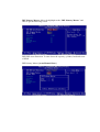
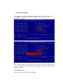
6.2 Main Menu
When the Setup program is accessed, the following screen appears. Move arrow
keys to the appropriate place you will setup and press “Enter” for selection.
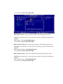
6.2.1 Standard CMOS Features
Choose the “Standard CMOS Features” option from main menu. The
“Standard CMOS Features” allows users to configure system components such
as date, time, hard disk drive and floppy drive types showed in the screen below:
Date (mm:dd:yy): Set the system date. The format is month, day and year. Move
to proper place by arrow keys in order to modify the values by Page Up/+ Key or
Page Down/- Key.
Time (hh:mm:ss): change internal clock.
IDE Primary Master: Move the highlight to the “IDE Primary Master” and
enter to get the following screen.
IDE HDD Auto-Detection: To auto-detect the capacity, cylinder, head and sector
of HDD
IDE Primary Master: [Auto/Manual/None]
Access Mode: [Auto/Large/LBA/CHS]
IDE Primary Slave: Choose the option then get the following three items.
IDE HDD Auto-Detection: To auto-detect the capacity, cylinder, head and sector
of HDD
IDE Primary Slave: [Auto/Manual/None]
Access Mode: [Auto/Large/LBA/CHS]
IDE Secondary Master: Choose the option then get the following three items.
IDE HDD Auto-Detection: To auto-detect the capacity, cylinder, head and sector
of HDD
IDE Secondary Master: [Auto/Manual/None]
Access Mode: [Auto/Large/LBA/CHS]
IDE Secondary Slave: Choose the option then get the following three items.
IDE HDD Auto-Detection: To auto-detect the capacity, cylinder, head and sector
of HDD
IDE Secondary Slave: [Auto/Manual/None]
Access Mode: [Auto/Large/LBA/CHS]
Drive A: Set the type of floppy drive installed by Page Up Key and Page Down.
Halt On: Set system halt on when specified item occurs.
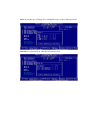
6.2.2 Advanced BIOS Features
Virus Warning: Allows you to choose the virus warning feature for IDE hard disk
boot sector protection. If this function is enabled and someone attempt to write data
into this area, BIOS will show a warning message on screen and alarm beep.
CPU Internal Cache [Enabled/ Disabled]
External Cache [Enable/Disable]
CPU L2 Cache ECC checking [Enabled/ Disabled]
Processor Number Feature [Enable/Disable]
Quick Power On Self Test (POST) [Enabled/Disabled]: Allows the system to
skip certain tests while booting. This will decrease the time needed to boot the
system.
First Boot Device [Floppy/SCSI/CD-ROM/HDD/LAN/Disabled]: Select your
boot device priority
Second Boot Device [Floppy/SCSI/CD-ROM/HDD/LAN/Disabled]: Select your
boot device priority
Third Boot Device [Floppy/SCSI/CD-ROM/HDD/LAN/Disabled]: Select your
boot device priority
Boot Other Device [Enabled/Disabled]: Select your boot device priority
Swap Floppy Drive [Enabled/Disabled]: If the system has two floppy drives,
choose physical drive B to logical drive A and vice versa.
Boot Up Floppy Seek [Enabled/Disabled]: Enable-During POST, BIOS will
determine if the floppy disk drive installed is 40 or 80 tracks. A 360 KB type drive
is 40 tracks; while 720 KB, 1.2 MB, and 1.44 MB type drives are all 80 tracks.
Disable- BIOS will not search for the floppy drive type by track number.
Boot on NumLock status [On/Off]: Select power on state for NumLock.
Gate A20 Option [Fast/Normal]: Fast- let chipset control Gate A20; Normal-a
pin in keyboard controller controls Gate A20. Default is set “Fast”.
Typematic Rate Setting [Enabled/Disabled]: Keystrokes repeat at a rate
determined by keyboard controller. When enabled, the typematic rate and
typematic delay can be selected.
Typematic Rate (Chars/Sec): BIOS accepts the following input values
(characters/second) for typematic rate: 6, 8, 10, 12, 15, 20, 24 and 30.
Typematic Delay (msec): Typematic delay is the time interval between the
appearances of two consecutive characters, when holding down a key. The input
values for this category are: 250, 500, 750, 1000 (msec).
Security Option [System/Setup]: The setting determines whether the system will
boot up if the password is denied. Access to Setup is, however, always limited.
System- The system will not boot, and access to Setup will be denied if the correct
password is not entered at the prompt. Setup- The system will boot, but access to
Setup will be denied if the correct password is not entered at the prompt.
OS/2 selection for DRAM > 64MB[Non-OS2/ OS2]: Select OS2 if you are
running OS/2 Operating System with greater than 64MB of RAM on the system.
Console Redirection [Enable/Disable]
Baud Rate [38400/19200/14400/9600/…]
6.2.3 Advanced Chipset Features
System BIOS Cacheable [Enable/ Disable]
Video BIOS Cacheable [Enable/ Disable]
Power supply Type [AT/ATX]: Default set “AT”
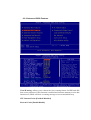
6.2.4 Integrated Peripherals
On-Chip Primary PCI IDE [Enabled/Disabled]: The system provides an
onboard on-chipset PCI IDE controller that supports Dual Channel IDE. A
maximum of 4 IDE devices can be supported. If user installed the Off-Board PCI
IDE controller, the user must choose which channels to disable. This will depend
on the channel used in the PCI Off-Board add-on card.
IDE Primary Master/Slave PIO [Auto/Mode0/Mode 1-4]
Each channel has both a master and a slave, making four IDE devices possible.
Because each IDE device may have a different Mode timing (0,1,2,3,4), it is
necessary for these to be independent. The default setting “Auto” will allow
auto-detection to ensure optimal performance.
IDE Primary Master/Slave UDMA [Auto/Disabled]
On-Chip Secondary PCI IDE [Enabled/Disabled]
IDE Secondary Master/Slave PIO [Auto/Mode0/Mode 1-4]
IDE Secondary Master/Slave UDMA [Auto/Disabled]
USB Controller [Enabled/Disabled]
USB Keyboard Support [Enabled/Disabled]: Choosing “Enabled” will allow
the system to use USB keyboard without device driver.
Init Display First [PCI slot/ AGP]
Onboard LAN chip #1 [Enable/ Disable]
Onboard LAN chip #2 [Enable/ Disable]
Onboard LAN chip #3 [Enable/ Disable]
Onboard LAN chip #4 [Enable/ Disable]
LAN Bypass Control [Enable/Disable]: for model with LAN bypass function
only.
IDE HDD Block Mode [Enabled/Disabled]: Enabled allows the Block mode
access for the IDE HDD
Onboard FDC Controller [Enabled/Disabled]: The system has an on-board
Super I/O chip with a FDD controller that supports a FDD Drive for 360K/
720K/1.2M/1.44M. Choose “Enabled” to use the on-board FDD controller for
accessing the FDD. Otherwise choose ”Disabled” to use the off-board FDD
controller.
Onboard Serial Port 1
[Auto/Disable/(3F8/IRQ4)/(2F8/IRQ3)/(3E8/IRQ4)/(2E8/IRQ3)]
Onboard Serial Port 2
[Auto/Disable/(3F8/IRQ4)/(2F8/IRQ3)/(3E8/IRQ4)/(2E8/IRQ3)]
The system has an On-board Super I/O chipset with 2 serial ports. The On-board
serial ports can be selected as:
Auto
Disable
3F8/IRQ4
COM 1 uses IRQ4
2F8/IRQ3
3E8/IRQ4
COM 2 uses IRQ3
COM 3 uses IRQ4
2E8/IRQ3
COM 4 uses IRQ3
ECP Mode Use DMA: In ECP Mode Use DMA, you can select DMA channel 1
or DMA channel 3. Leave this field on the default setting.
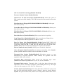
6.2.5 Power Management Setup
ACPI function [Enabled/ Disabled]
ACPI Suspend Type
Power Management:
Suspend Mode:
Video Off Option:
Video Off Method:
Switch Function:
MODEM Use IRQ:
HDD Off After:
Power Button Override:
Power State Resume Control:
PM Wake Up Events:
6.2.6 PnP/PCI Configurations
Reset Configuration Data [Disabled/Enabled]: Default is Disabled. Select
Enabled to reset Extended System Configuration Data (ESCD) when you exit
Setup if you have installed a new add-on and the system reconfiguration has caused
such a serious conflict that the OS cannot boot.
Resources Controlled by [Auto/Manual]: BIOS can automatically configure all
the boot and plug & play compatible devices. If you choose Auto, you cannot
select IRQ, DMA and memory base address fields, since BIOS automatically
assigns them.
PCI/VGA Palette Snoop [Disabled/Enabled]: Some display cards that are
nonstandard VGA, such as graphics accelerators or MPEG Video Cards, may not
show colors properly. The setting Enabled should correct this problem. Otherwise,
leave this on the setup default setting of Disabled. Recommend set Disabled.
6.2.7 PC Health Status
The system can monitor system voltage, CPU voltage, CPU temperature, system
temperature, CPU fan speed and system fan speed.
6.2.8 Frequency/Voltage Control
Auto Detect DIMM/PCI Clk [Enable/ Disable]
Spread Spectrum [Enable/ Disable]
6.2.9 Load Optimized Defaults
The option allows you to load the optimized default values for each of the
parameters on the Setup menus. When this option is pressed, a confirmation is
requested. Select “Y” to load the optimized default values. Select “N” or Press
“Esc“ to discard the selection.
6.2.10 Set Password
The option allows you to set or change user password. To set the user password,
press “Enter”. Type password and press “Enter”. You can type up eight
alphanumeric characters.
If the CMOS is good or if this option has been used to change the default password,
the user is asked for the password stored in the CMOS. The screen will display the
following message:
Confirm Password:
Input the current password and press “Enter”.
6.2.11 Save & Exit Setup
Once you finish your selection, choose the option to save the values you
selected to CMOS RAM. The CMOS RAM is sustained by an on board backup
battery and stays on even system is turned off. Once the option is selected, a
confirmation is asked. Select “Y” to save changes and exit.
6.2.12 Exit without Saving
The option should only be used if you do not want to save the changes you
have made to the Setup program. If you have made changes to the fields, the
system will ask for confirmation before existing. Select “Y” then the system will
keep previous values.
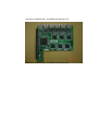
Chapter 7 LAN Expansion
POD-9578 can support maximum 4 LAN ports. With LAN expansion board, system
will offer up to 10 10/100Mbit Fast Ethernet ports.
Expansion LAN Board with 2 10/100Mbit Fast Ethernet Ports
Expansion LAN Board with 4 10/100Mbit Fast Ethernet Ports
Expansion LAN Board with 6 10/100Mbit Fast Ethernet Ports