1
!!"#$%&'#
()*+,-#.)/+0*#11#
!"#$%&&'(2#(,34-#5,6)-)7#897+,#8:;3+<+)-#6+=>#.(5#
!<<)?=/#
#
#
#
#
#
#
#
#
#
#
#
#
#
#
#
#
@)4:#A#&B2#
C90,#D4/=)334*,/#
(4*7-4#E9F,G#
H-)=?>)*#I+J)-4#
!
!
!
"!
"#$%&!'(!)'*+&*+,!
-.&/0+12&!3044#56777777777777777777777777777777777777777777777777777777777777777777777777777777777777777777777777777777777777777778#
8!"&/9*1/#%!'$:&/+12&,!#*;!5&<015&4&*+, 77777777777777777777777777777777777777777777777777777777777777777777777=#
878!>0;1'!>4?%1(1/#+1'*!30$,6,+&4 77777777777777777777777777777777777777777777777777777777777777777777777777777777777777777777 =#
87=!@1A1+#%!31A*#%!B5'/&,,1*A!30$,6,+&4 77777777777777777777777777777777777777777777777777777777777777777777777777777777777 =#
87C!B'D&5!E#*#A&4&*+!36,+&47777777777777777777777777777777777777777777777777777777777777777777777777777777777777777777777777777 =#
87F!E'*1+'51*A!30$,6,+&477777777777777777777777777777777777777777777777777777777777777777777777777777777777777777777777777777777777777 C#
=!"&/9*'%'A6!G&,/9 7777777777777777777777777777777777777777777777777777777777777777777777777777777777777777777777777777777777C#
=78!B5&21'0,!H'5I,!J!3141%#5!B5':&/+, 777777777777777777777777777777777777777777777777777777777777777777777777777777777777777 C#
KL&L&#(+:+34-#5-,M)?=/LLLLLLLLLLLLLLLLLLLLLLLLLLLLLLLLLLLLLLLLLLLLLLLLLLLLLLLLLLLLLLLLLLLLLLLLLLLLLLLLLLLLLLLLLLLLLLLLLLLLLLLLLLLLLLLLLLLLLLLLLLLLLLLLLLLLLL N#
KL&LK#D,::)-?+43#8:;3+<+)-#5-,79?=/ LLLLLLLLLLLLLLLLLLLLLLLLLLLLLLLLLLLLLLLLLLLLLLLLLLLLLLLLLLLLLLLLLLLLLLLLLLLLLLLLLLLLLLLLLLLLLLLLLLLLL B#
=7=!3'%#5!B#*&%, 7777777777777777777777777777777777777777777777777777777777777777777777777777777777777777777777777777777777777777777777777777777777 K#
KLKL&#D-O/=433+*)#(+3+?,*#5P/ LLLLLLLLLLLLLLLLLLLLLLLLLLLLLLLLLLLLLLLLLLLLLLLLLLLLLLLLLLLLLLLLLLLLLLLLLLLLLLLLLLLLLLLLLLLLLLLLLLLLLLLLLLLLLLLLLLLLLLLL %#
KLKLK#@>+*#<+3:#5P/LLLLLLLLLLLLLLLLLLLLLLLLLLLLLLLLLLLLLLLLLLLLLLLLLLLLLLLLLLLLLLLLLLLLLLLLLLLLLLLLLLLLLLLLLLLLLLLLLLLLLLLLLLLLLLLLLLLLLLLLLLLLLLLLLLLLLLLLLLL %#
KLKLN#8:,-;>,9/#(+3+?,*#5P/ LLLLLLLLLLLLLLLLLLLLLLLLLLLLLLLLLLLLLLLLLLLLLLLLLLLLLLLLLLLLLLLLLLLLLLLLLLLLLLLLLLLLLLLLLLLLLLLLLLLLLLLLLLLLLLLLLLLLLL %#
=7C!L#++&51&, 7777777777777777777777777777777777777777777777777777777777777777777777777777777777777777777777777777777777777777777777777777777777777 8M#
KLNL&#"+=>+9:Q+,*#R4==)-+)/ LLLLLLLLLLLLLLLLLLLLLLLLLLLLLLLLLLLLLLLLLLLLLLLLLLLLLLLLLLLLLLLLLLLLLLLLLLLLLLLLLLLLLLLLLLLLLLLLLLLLLLLLLLLLLLLLLLLLLLL &S#
KLNLK#()43)7#")47#8?+7LLLLLLLLLLLLLLLLLLLLLLLLLLLLLLLLLLLLLLLLLLLLLLLLLLLLLLLLLLLLLLLLLLLLLLLLLLLLLLLLLLLLLLLLLLLLLLLLLLLLLLLLLLLLLLLLLLLLLLLLLLLLLLLLL &S#
KLNLN#T+?U)3#D47:+9: LLLLLLLLLLLLLLLLLLLLLLLLLLLLLLLLLLLLLLLLLLLLLLLLLLLLLLLLLLLLLLLLLLLLLLLLLLLLLLLLLLLLLLLLLLLLLLLLLLLLLLLLLLLLLLLLLLLLLLLLLLLLLLLLL &&#
KLNL$#T+?U)3#E)=43#CO7-+7)LLLLLLLLLLLLLLLLLLLLLLLLLLLLLLLLLLLLLLLLLLLLLLLLLLLLLLLLLLLLLLLLLLLLLLLLLLLLLLLLLLLLLLLLLLLLLLLLLLLLLLLLLLLLLLLLLLLLLLLL &K#
=7F!3'%#5!B'D&5!E#*#A&4&*+!E1/5'/'*+5'%%&5 77777777777777777777777777777777777777777777777777777777777777777777 8=#
KL$L-79+*,#E)04#K'BS LLLLLLLLLLLLLLLLLLLLLLLLLLLLLLLLLLLLLLLLLLLLLLLLLLLLLLLLLLLLLLLLLLLLLLLLLLLLLLLLLLLLLLLLLLLLLLLLLLLLLLLLLLLLLLLLLLLLLLLLLL &K#
KL$LK#@)V4/#1*/=-9:)*=#@E(NKSWKXSX LLLLLLLLLLLLLLLLLLLLLLLLLLLLLLLLLLLLLLLLLLLLLLLLLLLLLLLLLLLLLLLLLLLLLLLLLLLLLLLLLLLLLLLLLLLLLLL &N#
KL$LN#8=:)3#8PI#XQR+=#E+?-,?,*=-,33)-LLLLLLLLLLLLLLLLLLLLLLLLLLLLLLLLLLLLLLLLLLLLLLLLLLLLLLLLLLLLLLLLLLLLLLLLLLLLLLLLLLLLLLLLLLLLLLLL &N#
=7N!B'D&5!36,+&4!"'?'%'A677777777777777777777777777777777777777777777777777777777777777777777777777777777777777777777777777777777 8F#
=7O!@3B!)'4?'*&*+!G&,/9 7777777777777777777777777777777777777777777777777777777777777777777777777777777777777777777777777777 8N#
KLBL&#P&SSS(5#D>+; LLLLLLLLLLLLLLLLLLLLLLLLLLLLLLLLLLLLLLLLLLLLLLLLLLLLLLLLLLLLLLLLLLLLLLLLLLLLLLLLLLLLLLLLLLLLLLLLLLLLLLLLLLLLLLLLLLLLLLLLLLLLLLLLLLLLLL &B#
KLBLK#8-79+*,#YTZ#E+?-,?,*=-,33)-LLLLLLLLLLLLLLLLLLLLLLLLLLLLLLLLLLLLLLLLLLLLLLLLLLLLLLLLLLLLLLLLLLLLLLLLLLLLLLLLLLLLLLLLLLLLLLLLLLLLLL &[#
KLBLN#8.8Y&[SK#D>+;LLLLLLLLLLLLLLLLLLLLLLLLLLLLLLLLLLLLLLLLLLLLLLLLLLLLLLLLLLLLLLLLLLLLLLLLLLLLLLLLLLLLLLLLLLLLLLLLLLLLLLLLLLLLLLLLLLLLLLLLLLLLLLLLLL &[#
=7P!E1/5'/'*+5'%%&5!('5!@1,?%#6!G&,/9 777777777777777777777777777777777777777777777777777777777777777777777777777777 8Q#
KL[L&#E+?-,?>+;#51D&XWX[\%S#:+?-,?,*=-,33)- LLLLLLLLLLLLLLLLLLLLLLLLLLLLLLLLLLLLLLLLLLLLLLLLLLLLLLLLLLLLLLLLLLLLLLLLLLLLLLLL &%#
KL[LK#W-))/?43)#ED%(SX"CB$#:+?-,?,*=-,33)- LLLLLLLLLLLLLLLLLLLLLLLLLLLLLLLLLLLLLLLLLLLLLLLLLLLLLLLLLLLLLLLLLLLLLLLLLLLLLLLL KS#
KL[LN#8-79+*,#5-, LLLLLLLLLLLLLLLLLLLLLLLLLLLLLLLLLLLLLLLLLLLLLLLLLLLLLLLLLLLLLLLLLLLLLLLLLLLLLLLLLLLLLLLLLLLLLLLLLLLLLLLLLLLLLLLLLLLLLLLLLLLLLLLLLLLLLLLLLL K&#
=7K!R)@!)'4?'*&*+!G&,/9 7777777777777777777777777777777777777777777777777777777777777777777777777777777777777777777777777777 ==#
KLXL&#C+=4?>+#C.$$[XS#"D.LLLLLLLLLLLLLLLLLLLLLLLLLLLLLLLLLLLLLLLLLLLLLLLLLLLLLLLLLLLLLLLLLLLLLLLLLLLLLLLLLLLLLLLLLLLLLLLLLLLLLLLLLLLLLLLLLLLLLL KK#
KLXLK#T,U+4#NN&SLLLLLLLLLLLLLLLLLLLLLLLLLLLLLLLLLLLLLLLLLLLLLLLLLLLLLLLLLLLLLLLLLLLLLLLLLLLLLLLLLLLLLLLLLLLLLLLLLLLLLLLLLLLLLLLLLLLLLLLLLLLLLLLLLLLLLLLLLLLL KN#
=7Q!>0;1'!>4?%1(1&5!"&/9*'%'A1&, 77777777777777777777777777777777777777777777777777777777777777777777777777777777777777777777 =F#
KL%L&#P43J)/ LLLLLLLLLLLLLLLLLLLLLLLLLLLLLLLLLLLLLLLLLLLLLLLLLLLLLLLLLLLLLLLLLLLLLLLLLLLLLLLLLLLLLLLLLLLLLLLLLLLLLLLLLLLLLLLLLLLLLLLLLLLLLLLLLLLLLLLLLLLLLLLLLLLLLL K$#
KL%LK#(,3+7Q(=4=)#8:;3+<+)-/ LLLLLLLLLLLLLLLLLLLLLLLLLLLLLLLLLLLLLLLLLLLLLLLLLLLLLLLLLLLLLLLLLLLLLLLLLLLLLLLLLLLLLLLLLLLLLLLLLLLLLLLLLLLLLLLLLLLLLL K'#
KL%LN#(6+=?>+*0#8:;3+<+)-/ LLLLLLLLLLLLLLLLLLLLLLLLLLLLLLLLLLLLLLLLLLLLLLLLLLLLLLLLLLLLLLLLLLLLLLLLLLLLLLLLLLLLLLLLLLLLLLLLLLLLLLLLLLLLLLLLLLLLLLLL N&#
KL%L$#T,+/)LLLLLLLLLLLLLLLLLLLLLLLLLLLLLLLLLLLLLLLLLLLLLLLLLLLLLLLLLLLLLLLLLLLLLLLLLLLLLLLLLLLLLLLLLLLLLLLLLLLLLLLLLLLLLLLLLLLLLLLLLLLLLLLLLLLLLLLLLLLLLLLLLLLLLLLL N$#
!
""!
KL%L'#@>)-:43#T,+/) LLLLLLLLLLLLLLLLLLLLLLLLLLLLLLLLLLLLLLLLLLLLLLLLLLLLLLLLLLLLLLLLLLLLLLLLLLLLLLLLLLLLLLLLLLLLLLLLLLLLLLLLLLLLLLLLLLLLLLLLLLLLLLLLLLLLL N$#
=78M!>0;1'!S*+&5(#/&, 77777777777777777777777777777777777777777777777777777777777777777777777777777777777777777777777777777777777777777777 CN#
KL&SL΁+,#D,**)?=,-/#4*7#D4]3)/ LLLLLLLLLLLLLLLLLLLLLLLLLLLLLLLLLLLLLLLLLLLLLLLLLLLLLLLLLLLLLLLLLLLLLLLLLLLLLLLLLLLLLLLLLLLLLLLLLLLL N'#
KL&SLK#1:;)74*?)#E4=?>+*0#4*7#R-+70+*0LLLLLLLLLLLLLLLLLLLLLLLLLLLLLLLLLLLLLLLLLLLLLLLLLLLLLLLLLLLLLLLLLLLLLLLLLLLLLLLLLLLLLLLLLL N[#
KL&SLN#5-)Q8:;3+<+?4=+,* LLLLLLLLLLLLLLLLLLLLLLLLLLLLLLLLLLLLLLLLLLLLLLLLLLLLLLLLLLLLLLLLLLLLLLLLLLLLLLLLLLLLLLLLLLLLLLLLLLLLLLLLLLLLLLLLLLLLLLLLLLLL NX#
=788!>0;1'!-<0#%1T1*A 7777777777777777777777777777777777777777777777777777777777777777777777777777777777777777777777777777777777777777777 CQ#
KL&&L&#R4?U0-,9*7LLLLLLLLLLLLLLLLLLLLLLLLLLLLLLLLLLLLLLLLLLLLLLLLLLLLLLLLLLLLLLLLLLLLLLLLLLLLLLLLLLLLLLLLLLLLLLLLLLLLLLLLLLLLLLLLLLLLLLLLLLLLLLLLLLLLLLLL N%#
KL&&LK#897+,#W+3=)-/ LLLLLLLLLLLLLLLLLLLLLLLLLLLLLLLLLLLLLLLLLLLLLLLLLLLLLLLLLLLLLLLLLLLLLLLLLLLLLLLLLLLLLLLLLLLLLLLLLLLLLLLLLLLLLLLLLLLLLLLLLLLLLLLLLLLLLL $S#
C7!@&,1A*77777777777777777777777777777777777777777777777777777777777777777777777777777777777777777777777777777777777777777777777777777777777 F=#
C78!)'4?'*&*+!,&%&/+1'*77777777777777777777777777777777777777777777777777777777777777777777777777777777777777777777777777777777777777 F=#
NL&L,6)-#(9;;3OLLLLLLLLLLLLLLLLLLLLLLLLLLLLLLLLLLLLLLLLLLLLLLLLLLLLLLLLLLLLLLLLLLLLLLLLLLLLLLLLLLLLLLLLLLLLLLLLLLLLLLLLLLLLLLLLLLLLLLLLLLLLLLLLLLLLLLL $K#
NL&LK#R4==)-O LLLLLLLLLLLLLLLLLLLLLLLLLLLLLLLLLLLLLLLLLLLLLLLLLLLLLLLLLLLLLLLLLLLLLLLLLLLLLLLLLLLLLLLLLLLLLLLLLLLLLLLLLLLLLLLLLLLLLLLLLLLLLLLLLLLLLLLLLLLLLLLLLLLL $B#
NL&LN#E+?-,?,*=-,33)-LLLLLLLLLLLLLLLLLLLLLLLLLLLLLLLLLLLLLLLLLLLLLLLLLLLLLLLLLLLLLLLLLLLLLLLLLLLLLLLLLLLLLLLLLLLLLLLLLLLLLLLLLLLLLLLLLLLLLLLLLLLLLLLLLLL $X#
NL&L$#.+/;34O#(?-))* LLLLLLLLLLLLLLLLLLLLLLLLLLLLLLLLLLLLLLLLLLLLLLLLLLLLLLLLLLLLLLLLLLLLLLLLLLLLLLLLLLLLLLLLLLLLLLLLLLLLLLLLLLLLLLLLLLLLLLLLLLLLLLLLLLLLL $%#
NL&L'#.(5#D,:;,*)*= LLLLLLLLLLLLLLLLLLLLLLLLLLLLLLLLLLLLLLLLLLLLLLLLLLLLLLLLLLLLLLLLLLLLLLLLLLLLLLLLLLLLLLLLLLLLLLLLLLLLLLLLLLLLLLLLLLLLLLLLLLLLLLLLLL 'K#
C7=!@&,1A*!S4?%&4&*+#+1'*777777777777777777777777777777777777777777777777777777777777777777777777777777777777777777777777777777777 NC#
NLKL&#R4==)-O#D>4-0)-#D+-?9+= LLLLLLLLLLLLLLLLLLLLLLLLLLLLLLLLLLLLLLLLLLLLLLLLLLLLLLLLLLLLLLLLLLLLLLLLLLLLLLLLLLLLLLLLLLLLLLLLLLLLLLLLLLLLLLLLLLL 'N#
NLKLK#5,6)-#.+/=-+]9=+,*LLLLLLLLLLLLLLLLLLLLLLLLLLLLLLLLLLLLLLLLLLLLLLLLLLLLLLLLLLLLLLLLLLLLLLLLLLLLLLLLLLLLLLLLLLLLLLLLLLLLLLLLLLLLLLLLLLLLLLLLLLLL '[#
NLKLN#E,*+=,-+*0#(9]/O/=):#R3,?U#.+40-4:^(?>):4=+? LLLLLLLLLLLLLLLLLLLLLLLLLLLLLLLLLLLLLLLLLLLLLLLLLLLLLLLLLLLLL 'X#
NLKL$#897+,#(9]/O/=):LLLLLLLLLLLLLLLLLLLLLLLLLLLLLLLLLLLLLLLLLLLLLLLLLLLLLLLLLLLLLLLLLLLLLLLLLLLLLLLLLLLLLLLLLLLLLLLLLLLLLLLLLLLLLLLLLLLLLLLLLLLLLLLL BS#
NLKL'#897+,#8:;3+<+)- LLLLLLLLLLLLLLLLLLLLLLLLLLLLLLLLLLLLLLLLLLLLLLLLLLLLLLLLLLLLLLLLLLLLLLLLLLLLLLLLLLLLLLLLLLLLLLLLLLLLLLLLLLLLLLLLLLLLLLLLLLLLLLLLLL [&#
!!!!!C7C!E1/5'/'*+5'%%&5!)';1*A777777777777777777777777777777777777777777777777777777777777777777777777777777777777777777777777777777777 P=!
C7F!U2&5#%%!@&,1A* 77777777777777777777777777777777777777777777777777777777777777777777777777777777777777777777777777777777777777777777777777 PF#
F7!B5'+'+6?1*A7777777777777777777777777777777777777777777777777777777777777777777777777777777777777777777777777777777777777777777777777 PN#
F78!B&5,'**&%!@1,+51$0+1'*7777777777777777777777777777777777777777777777777777777777777777777777777777777777777777777777777777777777 PN#
F7=!>0;1'!30$,6,+&4!B5'+'+6?1*A777777777777777777777777777777777777777777777777777777777777777777777777777777777777777777777 PO#
F7C!B'D&5!30$,6,+&4!B5'+'+6?1*A77777777777777777777777777777777777777777777777777777777777777777777777777777777777777777777 PQ#
F7F!E'*1+'51*A!30$,6,+&4!B5'+'+6?1*A 7777777777777777777777777777777777777777777777777777777777777777777777777777777777 KM#
F7N!B)L 77777777777777777777777777777777777777777777777777777777777777777777777777777777777777777777777777777777777777777777777777777777777777777777777 KM#
F7O!V1*#%!"&,+1*A777777777777777777777777777777777777777777777777777777777777777777777777777777777777777777777777777777777777777777777777777777 KC#
F7P!B#5+,!30??%1&5, 7777777777777777777777777777777777777777777777777777777777777777777777777777777777777777777777777777777777777777777777777 KF#
O!E1%&,+'*&,!#*;!V1*#*/1*A 77777777777777777777777777777777777777777777777777777777777777777777777777777777777777777777777 KK#
O78!L0;A&+!#*;!V1*#*/1*A 777777777777777777777777777777777777777777777777777777777777777777777777777777777777777777777777777777777777 KK#
O7=!E1%&,+'*&!)9#5+ 777777777777777777777777777777777777777777777777777777777777777777777777777777777777777777777777777777777777777777777777 KQ#
P7!3044#56!#*;!)'*/%0,1'* 7777777777777777777777777777777777777777777777777777777777777777777777777777777777777777777777 Q=#
K7!>??&*;1/&, 7777777777777777777777777777777777777777777777777777777777777777777777777777777777777777777777777777777777777777777777777 QC#
K78!L1$%1'A5#?96 77777777777777777777777777777777777777777777777777777777777777777777777777777777777777777777777777777777777777777777777777777 QC#
K7=!)'?651A9+!B&541,,1'*, 7777777777777777777777777777777777777777777777777777777777777777777777777777777777777777777777777777777777 QN#
!
"""!
Executive Summary
Musicians and music enthusiasts are always looking for new ways of sharing
their craft with other people. Sound recording technologies such as magnetic
tape and compact discs allowed them to deliver their recorded performances to
wider audiences. Still, live music performances are an irreplaceable part of a
musicianʼs life. Musicians that use electrical instruments such as keyboards and
electric guitars are at a disadvantage with respect to their acoustic counterparts
since they depend in having electronic amplifiers and being attached on the
power grid to play. A solar powered amplifier would give them more freedom to
play anywhere they wanted too without being tied to the regular power grid.
Possible uses of this device could be as personal amplifiers for street performers,
music system for outdoor parties or a public address system for small campsites
or any other kind of public event where connecting to the power grid is difficult or
impossible. This is the main goal of the “Unplugged” sound system.
The motivation to take on this enterprise comes from the personal desire of team
members to be able to play musical instruments or just enjoy music from a laptop
computer or iPod without the need of running long and cumbersome extension
cords. The design for the Unplugged sound system includes one input for either a
low impedance microphone, or a musical instrument such as electro-acoustic
guitars and an 1/8 inch connector capable of interfacing a laptop computer or
MP3 player. The systemʼs versatility is further enhanced with the inclusion of the
BTSE-16FX DSP effects module. This module will let the user implement one of
sixteen different audio effects in the audio source of their choice. At the core of
this design is the TDA7396 amplifier chip which is capable of delivering a power
output of 45 Watts RMS into a 4 Ω speaker. The whole system is powered by a
12 Volt 5 ah SLA battery that is trickle charged by a 20 Watt photovoltaic cell.
!
!
!
!
!
!
!
!
!
#!
1 Technical objectives and requirements
There are three well-defined subsystems within the Unplugged sound system.
These are: audio amplification, digital signal processing and Power
collection/management subsystems. These posses different but complementary
technical objectives such as:
1.1 Audio Amplification Subsystem
-The device will be capable of driving 2 different audio sources for a period of 3
minutes or more.
-Each analog audio input will be equipped with a two-tone control circuit with a
dynamic range of +/- 6 dB to compensate for any acoustical inadequacies of the
environment where the sound system is used
-Each individual analog input must posses a dedicated level control.
-Should weight less than 30 pounds
-The system will include a ¼ inch TRS input for a microphone or instrument level
signals and an 1/8 inch input for an iPod or auxiliary audio source.
1.2 Digital Signal Processing Subsystem
-The user must be able to pick between audio effects of digital reverbs, delays
and halls and in which analog audio input they will act.
-The latency between the implementation of the audio effect and the userʼs input
must be minimal since the device is meant to be used in live performance.
-The user must be able to regulate how loud the audio effect is with respect to
the clean audio input being applied.
1.3 Power Management System
-The system must be capable of fully charging the SLA battery for optimal
operation of al peripheral devices.
-The system must be able to run off a 12V battery.
-The battery must be charged solely by a 20W solar panel
!
$!
1.4 Monitoring Subsystem
-User must be able to monitor parameters such as battery voltage, solar panel
voltage and state of charge of the battery.
-User must be able to monitor which effects is applied to the microphone/
instrument input.
-The measurements for solar panel and battery voltage must be accurate to the
nearest tenth of volt.
2 Technology Research
2.1 Previous Works / Similar Projects
In this section we would like to discuss both retail products and student projects
that have been found as a result of research for this project. Many projects have
been found that relate to this project. In the wide array of similar products, we
found three to be more relevant with the rest. These three previous works will be
discussed below.
2.1.1 Similar Projects
This project is a very basic student project. The amplifier is charged through solar
panels, and it is meant solely to work outside, as it has no battery. The student
was able to build the project during a summer break as it is described on the
website. The student designed his own amplifier circuit using an amplifier chip,
and also designed the circuit in order to charge this amplifier circuit through the
solar panels. As this project is very basic, no sound effects of any type were
used. This project also used a PCB sold at Radio Shack. The project box is a set
of two old speaker boxes that were transformed in order to hold the amplifier
circuit and the solar panels.
Again, as mentioned before this project seems to be very simple when compared
to the project at hand. The project discussed does not have any type of
microcontrollers or power management system. It also does not have a battery,
which it is an essential part of this project. The last part where both project differs
are audio effects. While this project has a DSP effects module, the project
discussed does not. Even though there are many differences between both
projects, it is worth mentioning this project during the research section because it
can be used as a learning tool.
!
%!
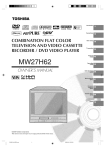
Figure 2.1.1.1: Solar Powered Amplifier Project. Used with permission from
Instructables.com
The student working on this project has step-by-step instructions on how to
create and mount this amplifier into a project box. It also includes specific parts
and schematics on the amplifier circuit. All these instructions come as a great
benefit to the team as no one in the team had a lot of experience mounting parts
to a project box or dealing with solar panels. From figure 2.1.1.2, it can be seen
how simple and rustic this project is. At the same time, it was a great steppingstone for the team to get familiarized with solar panels and project box mounting.
The second similar project that will be discussed is the Solar Amp. This project
was the first one to come up in the research phase that actually uses solar
panels to charge a battery. This project is made up of a lead acid gel cell 7.2Ah,
a premade car amplifier, and two effects pedals. The amplifier on this project
provides up to 150 Watts RMS, it also provides two amplification channels into 4
Ohms speakers. It is claimed by the creator that it takes 3-4 hours of charge in
order to get about 1 hour of music playing. This amplifier also comes with two
audio effects that are created through guitar pedals. The two guitar pedals are
powered by the battery and diodes are used to lower the 12 V battery input to the
9 V required by the pedals to operate. This amplifier also includes 3 panel
meters, one for charging current, one for battery voltage, and one for
consumption current. Below is a picture of the Solar Amp both from the solar
panel side and the side showing the connections of the pedals and the amplifier.
!
&!
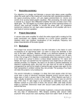
Figure 2.1.1.2: Solar Amp. Used with permission from Jason Waddell
From both of the figures above it can be seen that this project is much more
sophisticated that the first project described in this section. The project casing is
sturdier and the amplifier actually includes some audio effects. It can be said that
out of all the researched solar powered amp projects, this is the one closest to
the teamʼs senior design project. There are some major differences that are
worth mentioning in this case. Everything used to create this project is pre-made.
For the senior design project, every part of the project was designed by one of
the team members, which adds a level of difficulty that was not present when this
project was built. As it was mentioned before both the amplifier and the pedals
were bought and not designed by the creator of this project. This project also
lacks on the display department. Very few of the researched amplifiers actually
came with an LCD. For this project, it is not strange that it does not come with a
display since it also does not have a power management system and there would
not be any relevant information to display on the LCD. It is claimed by the
projectʼs creator that the amplifier works very well. Overall, the Solar Amp has
some relevance when related to the project described in this paper. The areas
where this project can directly impact the senior design project is the solar panel
mounting and charging circuit and the project casing. The creator of this project
has a lengthy discussion on how to encase the amplifier, which can be of great
help to the team as the project box is one of the areas that are not completely
decided. The author also provides the schematic of the circuit that charges the
battery using the solar panels. This schematic is also helpful when determining
the battery charging circuit.
!
'!
2.1.2 Commercial Amplifier Products
It came as a surprise to the group that there are no any products in the market
that closely match the description of this project. During the product research, the
team found that a lot of the commercial products partially matched this product
but not completely. The hardest feature to find in commercial grade products was
solar panels. The products described below are the ones that most closely
matched the product, but as mentioned before, there was not one product that
was identical to this project.
The first product discussed will be Roland Mobile Cube. This amplifier is a
battery-powered stereo amplifier. It supports several inputs, as guitar, keyboards,
computer audio, and MP3s. It also includes built-in audio effects as overdrive,
chorus, delay and reverb. The effects are controlled through potentiometers. One
of the reasons that make this amplifier so interesting is the fact that it runs on
batteries so it is completely portable. It is also very small. Only measuring 111/16" (W) x 4-1/4" (D) x 7" (H), and weighting 5 lb. 9 oz. It also provides about
5W stereo power. This product retails for about $169.00.
This amplifier includes a lot of the qualities that were desired for the amplifier in
this project. The size that this amplifier presents is excellent for a portable device.
This amplifier also includes many of the effects that were desired for this project.
Given how small the amplifier is, the effects are most likely created through a
DSP chip, which is desired for the teamʼs amplifier. Overall this product seems
stay close to some of the projectʼs desired specifications. Some other
specifications are not closely matched by this product. One place where the
Roland Mobile Cube differs from this project is stereo power. This amplifier gives
about 5W of stereo power while the amplifier in this project is designed to provide
about 45-55W of stereo power. They also differ on an LCD display. As discussed
before, the amplifier in this project includes an LCD display to show battery
power. The discussed product does not have any type of display. The last, and
most important, difference is the way this product is charged. It was discussed
before that this product works through batteries, and the Unplugged charges
through solar panels. Given that there is not any charging of batteries going on,
the discussed project does not have a need of power management system,
which were essential when this project was built. Overall, the Roland Cube offers
some good features for the price, but the amplifier discussed in this paper will
definitely posses more features and some improvements over the ones available
with the Roland Cube.
The second product discussed in this section will be the Regen ReVerb SolarPowered iPod Dock. This product is one of the only solar powered amplifiers
found on the market. The first feature to point out on this amplifier is that it only
designed to amplify an iPod or iPhone signal. It also stands about 3 ft tall, and is
able to provide about 60 Watts of power. This amplifier is also designed to be
!
(!
charged through a regular wall outlet if solar charge is not desired. It is claimed
that the ReVerb takes about 6 hours of direct sunlight or 14 hours of direct
sunlight indoors to fully charge, and on this charge, it can play about 12 hours of
music at normal volume. The ReVerb offers a 4.5 x1.5 inches backlit LCD. This
product costs about $2,229.00.
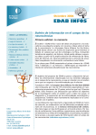
Figure 2.1.2.1: ReVerb Solar Powered iPod Dock. Used with permission
from regenliving.com
Again, as the Roland Cube, the Reverb does not fully match this projectʼs
description, but it does come closer to matching what the goals for this project
were. The first thing to point out about this project is price. It will be a very
expensive amplifier, especially when it is considered that it can only be used with
iPods. The second thing to pint out is that it not really portable. Even though the
ReVerb is charged with the sun, its size does not really allow it to be a very
portable device. The amplifier described in this project had portability as one of
its goals. The ReVerb is able to provide a little more watt power than what this
projectʼs stereo power. The ReVerb will be able to provide about 5-10 more
watts, which should not really make that big of a difference since volume is not
linearly related to the number of watts. The ReVerb includes a backlit LCD
display that shows how many hours of charge are left on the battery, the level of
sun it is receiving, and VU meters. This LCD provides more functionality than
what is provided by the Unplugged. The ReVerb is pictured on figure 2.1.2 figure
1. Overall, this amplifier, even though different in many ways to this projectʼs
specifications, seems to be the only product on the market that most closely fits
this projectʼs description.
!
)!
From the research in the existing product area, the biggest surprise discovered
was the fact that there is not one exact product that matches the functionality and
specifications of this project. It also came as a surprise that it was hard to find
senior design projects that related to the project described in this paper. The fact
that not many information on existing products or project is found might be a
disadvantage for the team. Information, especially from previous senior design
projects, is always desired as any mistakes or problems are clearly stipulated on
any documentation found in this area. The previous projects found presented a
foundation for the group to start the project on but did not clearly describe a
design process or any problems met along the way. Even though, the scarce
information on this type of products raised some concerns for the group, it also
pointed out that this project could be a marketable project. On section 2.1.2, the
Reverb was discussed along with its elevated price of $2,229.00. This price is
more than what the stipulated budget for this project is. After examining, and
researching the Regen ReVerb, and considering its hefty price for being just an
iPod amplifier, it became clear that the amplifier described on this project was
well budgeted for. The amplifier that the team built not only amplifies an iPod
input, it also amplifies a microphone or a guitar input. Considering all this, the
idea of marketing this project becomes more appealing, especially due to the fact
that there is not any product in the market that meets this characteristic. It was
assumed from the beginning of this project that many of this type of product
would be found on the Internet. The research in the area of commercial products
and existing products was invaluable as it opened doors into the future of this
project and created a drive for the members of the team to achieve a project, that
once designed and built, could be the first of its kind.
2.2 Solar Panels
Solar panels are made of many photovoltaic cells connected in series or parallel.
These photovoltaic cells are made of different semiconductor materials like
silicon. These materials are used because of the electrons they have in the
valance gap. This electrons produce energy once light is emitted to the solar
cells. Electric field makes electrons move freely which leads to the flow of current
in one direction. This and the voltage of solar cells are the parameters used to
get the watts that solar cells produce [1].
Using solar cells has many advantages. First, there are no moving parts. They
also have long life and are portable, which are some of the reasons to use them
for power systems. The highest efficiency for a commercial solar panel is 19%,
which means that it is going to convert 19% of the solar light emitted received
into electricity. These solar panels are manufactured by SunPower Silicon Valley,
but in general other companies have said that they have reached efficiency of
!
*!
less than 30% [2]. Different types of solar cells exist such as thin films, single
crystalline silicon, and polycrystalline among others.
2.2.1 Crystalline Silicon PVs
There are different types of crystalline solar cells. The first one is the single
crystal silicon cell, which are expensive to produce as they need to be grown
using the Czochralski method. On the other side, multicrystalline silicon PV cells
are less expensive to produce, but less effective. These cells are produced by
melting silicon, which is going to produce rectangular ingot of multicrystalline
silicon that is cut into blocks that are then put into thin wafers [3]. Overall,
crystalline silicon is considered to be a poor absorber of light reaching a
maximum cell efficiency of only 24.7% for the single crystalline silicon and 19%
for multicrystalline. To produce an output voltage to charge a 12V battery, 36
cells of crystalline silicon are soldered together in series [4]. These cells are
protected against weather effects and have warranty of 25 years.
2.2.2 Thin film PVs!
Thin film panels are produced by depositing thin layers of photovoltaic materials
on other materials such as plastic, stainless steel or glass [4]. Then, by using
laser technology single cells are created.
!
Some thin film technologies have reached efficiencies above 13%. The cost of
producing thin films cells is less expensive because all the cells are together;
therefore there is no need for them to be soldered together and mounted in
frames. !
2.2.3 Amorphous Silicon PVs
Amorphous silicon is the most common and developed thin film technology. Solar
panels made of this material can continue to charge at cloudy conditions. On the
other side, one clear disadvantage of amorphous silicon PVs is their short lifetime
because their power output decreases by 15-35% with the direct exposure of the
cells to the sun. Also, their efficiency ranges from 6-8%, which is smaller than
that of crystalline silicon [5].
Furthermore, the production of this silicon material is more complex because it is
mixed with germanium to improve the light absorption by reducing its band gap
[4].
Table 2.2.1 below shows maximum values for different types of solar cell
materials.
!
+!
2.3 Batteries
Nowadays, the use of rechargeable batteries has been critical in the design of
new technologies. There are many different rechargeable batteries types, but the
scope of this research will cover the four most important and widely used types.
2.3.1 Lithium-ion Batteries
One of the most important characteristics that lithium-ion batteries offer over
other batteries is that they have high energy densities, which means that they
can store more energy per space and weight than other batteries [9]. Lithium-ion
batteries are widely used in portable devices. It has an energy density which
doubles that of Nickel Cadmium. Also, they have no memory so there is no need
to discharge the batteries completely for them to give a 100% and the self
discharge rate is lower than that of other batteries, which explains why it retains
their charge for longer times.
!
This type of rechargeable batteries uses constant voltage to recharge them. This
process of recharging is completed once the current drops below the current
limit, which is set by the manufacturer. It also uses a current limiter to protect the
battery from overheating [9]. One clear drawback of using lithium ion batteries is
that they need to have a protection circuitry in order for them to work safely. What
this does is that it limits the peak voltage of each cell to prevent them from
reaching a low voltage during the discharge process [11].
They also have a higher cost of production than NiCad, which is around 40% less
expensive. Li-Ion batteries produce the same energy as Nickel Metal Hydride
batteries but have a weigh which is 35% less than NiMH. This is beneficial for
portable devices such as laptops, cameras, cell phones, among others because
battery weight is very important when deciding which portable to buy. Nowadays
portability is very important. The disposal of such batteries is less harmful for the
environment because they don't contain toxic materials such as Cadmium or
Mercury [8]
2.3.2 Sealed Lead Acid
Sealed Lead Acid batteries, also known as gel-cell batteries are also charged by
using constant voltage. A big difference between SLA and Li-I batteries is that
SLA are less expensive. They are usually used for alarm systems and also use a
current limiter to protect them from burning. One advantage that it offers is that it
can be charged for long times as long as the cell voltage does not exceed the
specifications [9]
!
#,!
A lead-acid battery is an electrical storage device that uses a reversible chemical
reaction to store energy. It uses a combination of lead plates or grids and an
electrolyte consisting of a diluted sulfuric acid to convert electrical energy into
potential chemical energy and back again. The electrolyte of lead-acid batteries
is hazardous to your health and may produce burns and other permanent
damage if you come into contact with it [7].!
!
This battery is used when very high power is required and is the most powerful
type of rechargeable battery on the market [8]. This type of batteries performs
well at high temperatures as they have been used on cars. Sealed Lead Acid
battery weighs more than other rechargeable batteries. They weigh twice as
much as the rest of the other rechargeable batteries and if this battery is
completely discharged it can be damaged with acid and will no longer work.
There is no way to fix this type of battery after this happens. For this reason this
battery needs to be constantly charged to expand its life time.
2.3.3 Nickel Cadmium
Nickel Cadmium recharging process is different from other batteries. NiCad uses
constant current to recharge itself. It is stated that it can be recharged over a
1000 times, but suffers from a high discharge rate [9].
The Nickel Cadmium battery was created in 1899, but began to be produced in
the United State in 1946. It is an old technology that has been in production for
over 50 years. One advantage of NiCad battery is that it has a long charge and
discharge cycle, which means that this type of battery does not recharge quickly
and discharges after long time. Nickel Cadmium batteries have the lowest
discharging rate of all rechargeable batteries excluding Sealed Lead Acid
batteries. They have a relative high current which is the principal reason for them
to be used in cordless power tool. This battery has an average life of 1000-1500
charges.
Compared to Nickel-Metal Hydride cells, NiCad batteries can retain energy for
longer times. One big problem that Nickel Cadmium suffers is that it creates
memory, which happens when the battery is recharged when the battery is not
completely discharged. Moreover, if the NiCad battery is charged after it reaches
it maximum charge value the amount of storage could be reduced because as it
is stated in [8], if the user let that happen the contact crystals in the battery are
going to increase in size; hence, the battery will have less area for energy to be
stored.
!
##!
2.3.4 Nickel Metal Hydride
Nickel Metal Hydride batteries are known to have a higher energy density than
NiCad, but using them have more disadvantages [9]. These types of batteries are
widely used in portable devices such as notebooks. One of the drawbacks of
these batteries is that they need to be recharged carefully because if they are
overcharged they can be damaged greatly. Another disadvantage that Nickel
Metal Hydride batteries have over other types of batteries is that they have a
discharging rate of 20% per month.
Nickel Metal Hydride batteries have a capacity to store 30% more energy than
Nickel Cadmium ones, but their charge cycle is less. These types of batteries do
not create memory if they are discharged completely, and recharge faster than
Nickel Cadmium batteries. Different from Lithium-Ion batteries the disposal of
such batteries is not harmful at all for the environment. !
As stated before, these batteries are widely used in notebooks. It is important to
know that new batteries do not charge as they are supposed to do when they are
new. Because of this, it is recommended to charge the battery completely and
use the computer until the battery dies, by doing so the battery will reach its full
capacity. This process is called the cycling the battery [8].
2.4 Solar Power Management Microcontroller
The microcontroller is a very important part of the project. It is what powers the
whole system and makes it smart. In order to find an efficient yet simple to
program microcontroller it was important to make some considerations like the
amounts of outputs and inputs needed for the whole connection of the solar
panels with the circuits, the A/D converter and the battery circuit.
2.4.1 Arduino Mega 2560
The Arduino Mega 2560 was the first microcontroller taken in consideration.
Arduino boards are well known because they are an open-source hardware
computing platform. It is a simple input/output board that can be programmed
using C language by using an open-source IDE. This microcontroller has 32
registers that are directly connected to an Arithmetic Logic Unit [13].
This microcontroller has:
4 Kbytes EEPROM
8 Kbytes SRAM
54 digital input/output pins
14 PWM
16 Analog inputs
4 UARTS
!
#$!
1 16 MHz crystal oscillator
256 KHz flash memory
USB connection
Aside from this, the microcontroller can be powered with AC to DC adapter, a
battery or by plugging it to a computer via the USB port. It also has an input
voltage of 7-12V and needs 5V to be powered.
2.4.2 Texas Instrument TMS320F2808
Another microcontroller taken in consideration is the Texas Instruments
TMS320F2808. This DSP microcontroller has 32 bits and has a speed of
100MHz, which is 5x greater than the Atmel mega microcontroller. It also
includes a 12 bit A/D converter that has a conversion speed of 160nSec. Other
characteristics are shown in table 2.4.1. The advantage of this is that there will
be no need to use an external A/D converter and everything will be together in
one piece, which makes the design more optimized an ideal for renewable
energy applications [10]. Also, it can be programmed using code composer
studio with C/Assembly.
TMS320F2808 Characteristics
Low power consumption 3.3-V I/O
64K x 16 Flash memory
18K x 16 SARAM memory
16 PWM channels
32-bit core
150 MHz conversion for 12-bit
ADC
Table 2.4.1: Shows the different characteristics of the TMS320F2808 MU.
2.4.3 Atmel AVR 8-Bit Microcontroller
The Atmel AVR microcontroller is another microcontroller that includes an A/D
converter on same chip. It has EEPROM, and flash memory. It can be
reprogrammed using fast In-System Programming (ISP) after it is assembled [9].
It can be programmed completely using C, which makes it simpler to program
and modify compared to other microcontrollers that need to be programmed
using assembly.
This microcontroller is good for battery chargers as the EEPROM data memory
can be used to store battery characteristics, such as charging processes. The
10-bit A/D converter allows batteries to reach their maximum charge value. With
this, the design will be also optimized and the cost will be reduced.
!
#%!
2.5 Power System Topology
There are two topologies taken in consideration for the design of the power
system: path selection and direct topology. As stated in [6], the purpose of using
a direct connection topology is to isolate the photovoltaic cell or any other power
supply from the battery and system by connecting the battery pack positive
terminal and the charger stage output to the system power bus, as shown in
Figure 2.5.1. In such a system, the maximum power delivered from the PV panel
to the system power bus is limited by the charger settings; the external supply is
isolated from the system power bus by the charger power stage.
System Power Bus
Figure 2.5.1 Direct Connection Topology
Using Direction connection topology has its pros and cons. As stated above, it is
used to isolate the photovoltaic cell or any other power supply from the battery
and system which have the following advantages:
1. The first advantage of constructing a direct connection topology is that it is
easier to implement and less expensive than path selection topology
because it does not need switching networks like MOSFETs and BJTs to
divide the power.
2. Another advantage is that the total charge current and the system current
can be limited by setting the charge current to a value chosen [6].
Also, there are various disadvantages of using direct topology on power systems.
1. As it is stated by TIʼs Implementation of Battery Charger, if a system
requires high current the charging process will never end; hence, the
battery is going to be always charging which reduces the life time of it.
2. Also, the battery may not charge completely and if the battery is low or
completely depleted the system voltage is going to be cut and will not
work.
!
#&!
On the other side, in path selection topologies, the input power is divided
between the charger stage and the system load. This topology is shown in Figure
2.5.2. As it is shown in the figure the PV panel is directly connected to the
system power bus and the power is divided by using a switch.
Figure 2.5.2 Path Selection Topology
Using this topology has various advantages.
1. The first notable advantage is that the battery charge is not affected by the
load of the system, this happens because the battery and the loads are
independent of each other as shown above in figure 2.5.2.
2. It also is able to make the power system reach high load current.
3. The most important advantage over the direct topology is that the system
will still work with low or depleted batteries because the PV panel will
provide energy required for the system to power up.
4. Also the efficiency can be higher than that of direct connection topology
because there will be high voltage difference between the input and
system voltages [6]
This topology also encounters different disadvantages.
1. Different from the direct topology this topology requires the use of switching
networks, which makes the cost of building power systems with this
topology to be more expensive and difficult to build.
2. There is more variation in the system voltage.
2.6 DSP Component Research
The advantages to choosing a DSP component over an analog component for
the audio processing that was implemented with this project were vast. Since
digital audio processing operates mathematically on a binary representation of
!
#'!
the signal, this allows a design of many audio effects through a small piece of
hardware which, in change, will help to meet the size requirements that were set
for this amplifier. The only concern that choosing digital signal processing
brought was the fact that it was not able to provide perfect filtering, demodulation
and other functions because of mathematical limitations. This can make the chip
prone to some loss of signal. After thoroughly researching available options and
with low power consumption as one of the main concerns for this project, the
conclusion was reached that the techniques of digital signal processing are much
more powerful and efficient than analog domain signal processing and they fit the
requirements for this project.
As research has advanced, there were many DSP products that were found fit for
this project. The main goal with a DSP component was to find a good quality
product that met the budget, had low power consumption, and also that could be
programmed very quickly as there was very limited time to implement our project.
2.6.1 V1000SP Chip
The first style of DSP chip that was considered for potential use in this project
was the V1000 Digital Multi-Effects DSP. The V1000 is a DSP chip that has 16
built-in reverb and multi-effects, and it also very affordable as each chip runs for
about ten dollars. This chip only needs a 4-bit microcontroller in order to
implement the effects that are already built in.
One of the biggest advantages to choosing this chip was the fact that many
effects that are desired for our project were already implemented. For instance,
echo, phaser, chorus, and flanger came already implemented. Added to the
implemented effects on the chip, is with a serially programmable SRAM. This
SRAM is used for either program development or dynamically changing
programs in case other effects need to be implemented. One of the
disadvantages of choosing this chip was that fact that a 4-bit microcontroller was
be needed. By having to add one extra microcontroller to the project, the budget
could have been exceeded. An extra microcontroller meant higher power
consumption than it was originally planned. The project complexity also
incremented, and the ever-present risk of not meeting the deadline was
increased. Another disadvantage to this chip was that it is not widely used. When
compared to other DSP components that have been researched, not a lot of
information was found on this chip, other than a couple blogs and the datasheet.
The goal for this project was to pick components that are widely used, as by
doing this, it was guaranteed that the there was availability of information on how
!
#(!
to use the component. It could be said that this was almost as important as any
of the other factors that were considered when choosing a DSP component.
Finding information that is readily available on working with the chip could
shorten programming time and also simplify implementation.
2.6.2 Arduino UNO Microcontroller
Another alternative for a DSP component considered for the implementation of
the project was the use of Arduino Uno Board. In this case the Arduino Uno
Board would be used for real time audio processing. The Arduino Uno is a
microcontroller board based on the Atmega328 microcontroller.
The use of this board for audio processing had many advantages that related to
the projectʼs implementation. One of the first and most important advantages was
the fact that these types of microcontrollers are widely known and used. As it was
mentioned earlier, one of the most important criteria when picking a DSP
component was to easily find information on how to program and use the
component. This requirement was fully met with this microcontroller. Information
and previous projects using this component are vastly found by a simple Internet
search. Another advantage to choosing this component was that it is an open
source product. By being open source, the price is lower compared to other
microcontrollers that were researched. This low price would help to stay within
budget, which as mentioned above, was also one of the main requirements. As
this component is a microcontroller itself, the need for a 4-bit microcontroller that
was discussed on the previous component option was eliminated. One of the
biggest disadvantages to choosing this component was that, as it is a
microcontroller and not a DSP chip, there was a need to add some extra
components to be able to implement the sound effects that were desired for this
project. This included a potentiometer to control the effects, capacitors, resistors,
and some type of filter on the audio output. This complicated implementation and
design since exact component values had to be chosen to be able to create the
effects that were desired. All these new components also consumed extra power
that was not accounted for, and created the risk of not meeting the deadline if
picking the exact components took longer than the estimated time.
2.6.3 ADAU1702 Chip
The last option discussed for the DSP component is the ADAU1702. The
ADAU1702 is a single chip audio system that includes audio DSP, ADCs, and
!
#)!
DACs. This chip was chosen as one of the options for several reasons. The main
reason was that this chip already includes AD/DA converters. This saved some
space on the PCB as well as making cable connection simpler. Another major
advantage to this board was the way it is programmed. Analog Devices provides
a program called “Sigma Studio” which provides an easy to use graphical user
interface. This GUI allowed for the programming of the DSP chip through
graphical components instead of the usual DSP programming needed on other
chips. This signified a faster programming time that what was originally
estimated. Considering the time constraints that were set for this project, this type
of advantage was very important. One of the main concerns when choosing a
DSP component was the way that the audio effects were controlled. Fortunately,
the ADU1702 chip has an on chip EEPROM, which could potentially avoid the
need for a microcontroller to control the audio effects. The EEPROM is controlled
through push buttons. This was an ideal alternative for our project. By avoiding a
microcontroller for the DSP chip, it helped to stay within budget and also
minimize power consumption. This covered two of the main concerns when
choosing a DSP component. Considering that this chip could use an 8-bit
microcontroller, the option of using one microcontroller to control both the DSP
chip and the LCD display was also researched. This option was explored fully on
other sections.
One disadvantage of choosing this chip was price. Both this chip and evaluation
board were more expensive that previous options discussed above. This was a
disadvantage that was not taken lightly as staying on budget was one of the main
concerns in this project.
When comparing the previously discussed options, it was found that they offer
advantages and disadvantages that were widely different. The first option
discussed, the V1000 Digital Multi-Effects DSP offered little programming but it
required a microcontroller that was not budgeted for. The second option had an
embedded microcontroller but was not a DSP chip, so to do real time audio
processing extra components were needed. The third option seemed to have the
most advantages that related to the goals for this project, but there was a need to
work around the budget since it was more expensive that what was initially
considered.
After all the research for DSP components and due to the many advantages that
the ADU1702 DSP chip offered, it was the most likely be implemented in the
design. Even though this chip was more expensive than what it was initially
!
#*!
budgeted for, this issue was easily resolved by avoiding the choice of a
microcontroller by using the on-chip EEPROM. It is believed that that this chip
would allow to create our audio effects faster than it would take with any of the
other two discussed options. The AD/DC converters were also of interest as this
could save space on the PCB.
2.7 Microcontroller for Display Research
There are several concerns that were taken into consideration when choosing a
microcontroller component for the projectʼs display. The first, and most important,
consideration was power consumption. The device chosen for this project must
consume very low power. The lowest power consumed, the better since the
project uses solar power to charge a battery. Once this battery is fully charged, it
is solely responsible for powering the device. By trying to keep power
consumption to a minimum, the charge on the battery lasts longer which was one
or our main goals. The second consideration when choosing this component was
budgeting. It had to be a device whose price fits into the budget for this project.
The last consideration was that it could adequately control a display. The main
task of this microcontroller was to control a display. This later consideration was
weighted heavily when choosing a device.
2.7.1 Microchip PIC18F87J90 microcontroller
The PIC18F87J90 has intergraded display drive capabilities up to 192 pixels. It is
also an 8-bit microcontroller, which was an advantage for the project when it was
considered that the DSP component chosen could be controlled with an 8-bit
microcontroller. Not only could this microcontroller be used for the display but it
could also be used to control our DSP component. This was a great advantage of
this microcontroller option. Another great feature that this chip offers was the
nanoWatt Technology, which can reduce power consumption by using alternate
run modes, multiple idle modes and on-the-fly mode switching. This microchip
microcontroller operates at an input voltage range of 2 to 3.6 volts, resulting in a
relatively low power microcontroller. From figure 2.7.1 it can be observed that the
PIC18F87J90 microcontroller provides 64-128 KB of flash memory, 2
comparators and an LCD Driver, which will not only met, but exceeded, the
requirements for this microcontroller to work in our project.
This Microcontroller seemed to be a good fit for our project. It met our budget and
power requirements. It also fits our display interfacing consideration. One more
!
#+!
benefit that is worth mentioning for this device, was that microchip provides a
segmented display designer GUI which allows programmer to easily create
segmented display code by dragging and dropping elements onto a screen. This
was a great benefit considering the time constraints of the project and the fact
that no person in the group had programmed a display with a microcontroller
before. Currently from the researching phase, this microcontroller does not have
any major disadvantages specifically related this project.
Figure 2.7.1: PIC 18F8790J90 Block Diagram. Used with permission from
Microchip.com
2.7.2 Freescale MC9S08LH64 microcontroller
The MC9S08LH64 microcontroller features a very low power consumption
operating at input voltage range of 1.8 to 3.6 volts. It is considered best in class
standby power consumption, which was a great benefit when considering the
goal of low power consumption that was established for this project. This
microcontroller provides up to 288 segments for the display. The LCD drive
included with this microcontroller can drive either a 3V or 5V LCD glass, which
provided flexibility when selecting the display component used for this project.
!
$,!
The MC9S08LH64 also includes two 32KB flash arrays, which provided enough
space for the code.
On fist glance, the MC9S08LH64 microcontroller appeared to be a good choice
when selecting a microcontroller. It met most projects expectations and goals. Its
low power consumption was backed by the Energy Efficient Solutions mark, and
its display capabilities seemed to exceed expectations. On further review of this
microcontroller, it was observed that it provided more functionality than what the
project required. The display drive offered more segments that what was needed
to implement the display. The microcontroller also offered functionalities that can
be applied to the medical field, and that will evidently was not used in this project.
After examining this option, it was clear that even though this chip met the
projectʼs goals, a simpler microcontroller could be used to achieve this projectʼs
required functionality.
2.7.3 Arduino Pro
The Arduino Pro microcontroller was also a great choice for this project. It comes
preassembled with the ATmega168 or ATmega328 chip depending on the model.
It also comes with 16 KB of flash memory, 14 digital input/output pins, and either
a 8 MHz or 16 MHz clock. It also offers the choice of two operating voltages, 3.3V
or 5V. As low power consumption was one of the main goals of this project, the
3.3V operating voltage would definitely be chosen over the 5V version since it will
draw less power and last longer on battery power. The input voltage range for
this board is 3.35V to 12V, which was somewhat high compared to the options
discussed above. One big advantage of the Arduino Pro was that it can be
programmed using a C compiler, which could greatly help to meet the deadline
since C is a language known by all the members of the group.
The Arduino Pro offered many advantages that impacted this project directly. All
of Arduino boards are open source products. By being open source, the price not
only met the budget requirements, it surpassed them. Another advantage to
being open source was that sample code was readily available on the Internet
helping the members of the team to get familiarized with programming the
Arduino board. There are two main disadvantages that were found from the
research on this board. The first was the fact that this board consumed more
power than the previously discussed options, and the second was the fact that
this board does not have a dedicated display driver as the other options did.
!
$#!
Even though the Arduino had some great features; it also had some major
downfalls when compared against the projects goals.
2.8 LCD Component Research
There were two main goals that needed to be met when selecting an LCD for this
project. First, and most important, the display had to be compatible with the
microcontrollers that were mentioned above on section 2.7. The display also
needed to provide enough functionality so that the required information from this
project could be displayed. Another important goal that the LCD needed to meet
was low power consumption. As it was constantly mentioned throughout this
project, low power consumption was a goal that all of our components had to
meet so that battery life was maximized. The last goal for this display was to
meet the budget requirement.
2.8.1 Hitachi HD44780 LCD
The HD44780 was the first option that will be considered to use in this project.
Some of this LCD features are:
• 5 × 8 and 5 × 10 dot matrix possible
• Low power operation support: 2.7 to 5.5V
• Wide range of liquid crystal display driver power 3.0 to 11V
• 4-bit or 8-bit MPU interface enabled
• 80 × 8-bit display RAM (80 characters max.)
• 9,920-bit character generator ROM for a total of 240 character fonts
The first advantage that was noticeably good for this project was the low power
consumption. This would allow staying within the power budget, a main issue in
our project. Another great feature of this display was price. This screen can be
bought starting at $7 on a 16x2 size. This price is a lot less than what the display
had been budgeted for, so it was a great fit for this project. It can also be
observed from the list of features that it works on either a 4-bit or an 8-bit
interface, which provided flexibility when the programming is performed. The
HD44780 is also a widely used display. Information on how to program this
display is readily available, and a C compiler can be used, which was an added
advantage since no member on the team has programmed an LCD before. Since
the main information displayed on this LCD is battery life, it seemed to be a great
fit for the project needs.
!
$$!
2.8.2 Nokia 3310
The second option discussed for a display is the Nokia 3310. Some of its
features are:
• Voltage: 3 - 3.3 V
• Dimensions of 40 x 38 mm
• 2 modes of display, normal/inverse
• 84 x 48 pixels
From the list of features, it can be observed that this LCD would also meet the
projectʼs power budget, as the previously discussed option. It would also meet
the monetary budget, as it runs for about $6 on the Internet. Even though it
meets some goals for this project, this LCD falls short on certain aspects when
compared to the other LCD choice for this project. One of the main aspects
where this LCD differs from the previous choice is availability of part and existing
information. The Nokia 3310 is not as popular as the HD44780; therefore,
existing information on the part is hard to find, and previous projects using the
part are very limited. This fact impacts the project greatly as previous projects
and existing code on the Internet are ways to get familiarized with how to
program the LCD. Finally, This LCD display is widely used for phone
applications which means that when the part is bought from a vendor on the
Internet, they will usually sell the LCD to be interfaced with the phone. Because
the LCD would not be used in this way, then it would require a PCB board to be
created. This would cost the group money and precious time that could be used
on a most important activity. After much research of this LCD, it is concluded that
its disadvantages would not make it the best choice to use in this project. Figure
2.8.2.1 displays a picture of the Nokia 3310 when used for a thermometer
application.
Figure 2.8.2.1 : Nokia 3310 Thermometer application. Used with
permission from neggadget.com.
!
$%!
2.9 Audio Amplifier Technologies
2.9.1 Valves
Before the inception of the BJT transistor in the early 1950ʼs the only active
electronic devices where vacuum tubes. The basic principle of operation of the
vacuum tube was thermionic emission. This is when a relatively high voltage
thermally excites a cathode and it discharges electrons into a vacuum. These
devices that could be used as signal amplifiers or switches. Valves are very
attractive to audiophiles and audio equipment designers because of their
linearity. Linearity in this context is their ability to take an input with a complex
waveform and multiply each and every one of the frequency components of that
signal by a constant factor. This goes back to the original principle of an amplifier
that does not favor any given frequency of an input and is able to take in a small
audio signal (20 Hz-20 kHz in the 100ʼs mV range) and output the same exact
signal with the same frequency content but at a much larger voltage. Also when
they are overdriven their distortion has a particular clipping characteristic in which
when the transient of an input waveform is “chopped off” it is done so gradually
instead of abruptly (like solid-state devices). This is the one and foremost
characteristic that still drives audiophiles to go through the trouble of localizing
valves and valve amplifiers.
The main disadvantages of valves are that they are very difficult to manufacture,
are extremely fragile and their power consumption is very high in comparison
with modern solid-state components. Valves are bulky when comparing them to
modern transistors, they posses an anode and a cathode encapsulated in a glass
container that needs to have as much air evacuated from it as possible. This is a
very expensive and cumbersome process. The fact that the casing of the Valve is
made out of glass adds to the fragility of it. A careless bump on the device or
even in the amplifiers case would ruin the valve. Lastly valves are power hungry
devices. In order for valves to work they must possess specialized power
supplies (adding to the bulkiness) able to deliver anywhere from 200 to 500 Volts
and above. This makes valve amplifiers potentially dangerous to people
unfamiliar with their operation principles. Having a power supply that steps up
voltages this high adds expensive transformers to the power supply as well as
the potential trouble of mains voltage filtering into the audio amplification circuitry,
this bit about mains voltage is true for all amplifiers, but it is specially troublesome
for such high voltage devices.
!
$&!
In short, valve amplifiers were the first solution for the need of amplifying and
audio signal as linearly as possible. A lot of the principles that make valve
amplifier operate are used for modern solid-state based designs. However, their
modern use is limited to a very small audiophile community and some older RF
frequency amplifiers.
2.9.2 Solid-State Amplifiers
Class A
Electronic amplifiers can take as input either current sources or voltage sources
and source out voltages or currents. This translates into 4 possible
configurations, which are the current controlled current source, the voltage
controlled current source (transconductance amplifier), the current controlled
voltage source (transimpedance amplifier) and last but not least the voltage
controlled voltage source. Of these four possible combinations the one most
relevant to our study of electronic amplifiers is the last one, voltage controlled
voltage sources. This is so because all audio signals from either instruments or
electro-mechanical transducers (microphones) is transmitted as an AC voltage
and is expected to go through several analog signal processing stages (preamps, amplifiers, filtering) and then be reproduced through a load (speaker) in
the form of a larger AC voltage. Class A amplifiers are the simplest configuration
of these electronic amplifiers. They basically consist of active electronic devices
(BJTʼs, FETʼs or Valves) and modulate the output with respect to the input by
taking potential energy (voltage) from the power supply or rails and shaping the
input signal into a replica of itself with a larger voltage swing. Class A amplifiers
are single-ended systems, which means that one single device takes care of
reproducing the amplified output waveform for both the positive and negative
cycles of it. Also, the concept of always-on amplification deserves a little further
discussion. Audio amplifier designers more accurately refer to this concept as the
conduction angle quantity. The conduction angle is analyzed as a circle which
means that a 360 degree angle refers to a system that has an input that is
“on”throughout the whole time of amplification. In the other hand a 180-degree
angle of flow refers to a system that is only amplifying through half of he input
cycle. Since the input is a waveform it has a positive cycle and a negative cycle
and a class A amplifier is on for the full duration of this cycles it is said that a
class A amplifier possesses a 360-degree angle of flow. Older amplifiers for TV
sets, transistor radios and guitar amplifiers used class-A topologies.
!
$'!
As is the case with all devices that use BJT transistors, 3 possible combinations
are possible: Common-Base, Common-Emitter and Common-Collector or
Voltage follower. For the sake of briefness only one of these kinds will be
discussed: the Common-Emitter. Like any device that uses NPN transistors
careful calculations for the system components must be done to maximize
voltage swing and minimize the DC off-set of the output with respect to the input.
All of the body of work derived for NPN transistors applies. The assumptions
needed to design a working audio class A amplifier are simplified by the fact that
the only critical bandwidth of operation is within 20 Hz and 20 kHz. In the other
hand careful consideration must be made of decoupling any DC component of
the output waveform before delivering it to the load, in this case a speaker. This
goes back to the way a speaker works. The diaphragm inside of a loudspeaker
moves back and forth in accordance to the variations of current delivered from
the audio amplifier. If a current is “pushed” into the speaker (positive polarity) the
diaphragm will move forward, if a current is “pulled” from the speaker (negative
polarity) the speaker will recede. Speakers are usually calibrated in such a way
that when no DC component is present in the signal the diaphragm rests at
exactly the middle of the points of minimum and maximum vibration within the
speaker driver. If any significant amount of DC current is present in the amplified
signals the speaker diaphragm will shift from the mid-point to a point forward
within the speaker driver. If the applied amplified audio signal is large enough this
can cause the speaker diaphragm to detach from the driver enclosure or even
break. To illustrate the simplicity of a single-stage class-A topology and the
characteristics of its corresponding output one is shown in figure 2.9.2.1.
Figure 2.9.2.1: Single Stage Class A amplifier with C-E configuration and
corresponding input and output characteristics. Reproduced with
permission of Wayne Storr from www.electronics-tutorials.ws
!
$(!
Could this be too good to be true?, a high fidelity reproduction of the small-signal
with only one active component, one voltage source and a handful of passive
components?. The answer is yes. Despite the ease of implementation of class-A
amplifiers they have major drawbacks when it comes to power efficiency. Since
the amplifier is being biased and draws a quiescent current constantly it means
that the device is radiating power regardless of whether an input is applied or not.
Also, when there is a signal applied the single transistor is always on for both the
positive and negative cycles of the input wave . A design like this translates in an
amplifier model with a relatively low efficiency that can be anywhere from 12% to
25% (Elliot), designs with current mirrors and other extra circuitry but with a
class-A output stage are even reported to be up to 40% (Storr). To put this in
perspective it means that a single-stage amplifier topology that is designed to
deliver 50 Watts must be fed with anywhere from 200W (best case) to 416 W
(worst case) of power. The other 82% to 75% of power would be dissipated in the
form of heat in the biasing resistors or within the actual body of the transistor.
This requires careful and extensive heat sinking of all class-A amplifiers. Despite
their horrendous power consumption, class A amplifiers are relatively simple to
design. They only need one active output device such as a transistor, and a
power supply so they would require less real state on an actual circuit board.
Also the active device that takes care of the amplification is the same at the
output. This is why class-A amplifiers are usually referred too as single-ended
devices. This means that a lot of real state can be saved when building a class-A
amplifier, this savings in space must be traded off with the overall lack of
efficiency and the need of using big and expensive heat sinks. Like all
engineering designs there is always a trade-off. In modern amplifier designs
class A amplifications is reserved for certain applications where power efficiency
is of little relevance to the operation of the system because their use is more
seldom. Systems such as building intercoms, public address systems for
buildings that use a 70.7 Volt constant voltage power source and even
workbench testing amplifiers come to mind.
Class B
An alternative to the “always-on” or 360 degree conduction angle of Class A is
the Class B implementation with a conduction angle of 180 degrees. This kind of
amplifier possesses two active output devices that complement each other. For
the sake of discussion we will assume that they are BJTʼs so one would be a
NPN transistor and the other one a PNP transistor. In a basic class B topology
the emitter of the NPN would be feeding into the emitter of the PNP. Each one of
!
$)!
these output devices conducts current for half of the sinusoidal cycle of the
output waveform, This is why it is said that they have a 180-degree conduction.
This translates into a device that takes a small signal, breaks it into its positive
sinusoidal components and its negative sinusoidal components, amplifies it and
then adds up the amplified waveforms to make a scaled up representation of the
small signal input. This greatly increases the power efficiency of the audio
amplifier since only one of the devices is on at any given time and it is only
required for it to amplify one half of the waveform to the rails of the amplifier. By
pure logic the power efficiency of a class B amplifier would be placed anywhere
between 25% and 50% efficiency, but designs with more active components and
high-gain, high-efficiency transistors have been able to generate power efficiency
figures of approximate 70% and have a theoretical efficiency ceiling of 78.53%
(Self 137) this is of course with no transmission losses or leakage currents of any
device which is never the case in practical applications. Theoretically all amplifier
classes could be implemented as battery operated devices. However the large
quiescent currents of transistors used as Class A amplifiers would make the use
of batteries for amplification of music signals very expensive. In the other hand a
transistor amplifier capable of delivering a 70% efficiency would require a much
smaller heatsink than a class A device with around 25% efficiency. This would
make the implementation of it in portable devices very attractive. This is why
most solid-state portable electronics prior to the invention of modern switching
amplifiers would favor a class B design approach. They can be found in all kinds
of portable electronics such as TV sets and transistor radios. In order to further
understand the operation mode of class B amplifiers a representation of the
principle by which class B amplifiers operate can be appreciated in figure 2.9.2.2.
Figure 2.9.2.2: Single Stage Class B amplifier with complementing BJT
transistors Reproduced with permission of Wayne Storr from
www.electronics-tutorials.ws
!
$*!
The class B topology poses an elegant solution to the problem of audio amplifier
power efficiency. Break the wave apart, amplify each cycle by separate and then
add them up to get back an original waveform with an increased voltage swing.
This approach of generating a positive bias across the base and emitter of the
first transistor, hence delivering a current to the load and then proceeding to
create a positive bias across the second transistor and creating a current coming
from the load is called the push-pull output configuration. The main problem with
this kind of topology resides in the PNP transistor in the bottom of the schematic.
Since for the transistors to turn-on they must have a 0.7 V bias between the
collector and the emitter, otherwise they will not conduct. Theoretically this
means that any part of the amplified audio signal that falls below 0.7 V will not be
go through the PNP so it will not be added to the final waveform of the amplifier.
Likewise, if a bias of 0.7 Volts is not present across the NPNʼs base and emitter it
will not conduct. In reality a certain amount of signal will be generated from all the
emitter currents, however it is very small. This will cause for the parts of the
amplified signal that fall below the window that exists at the 0.7 volt point and
above the -0.7 volt point to not be reproduced with great precision by the
amplifier. Since this unpredictable output only occurs when the amplified
waveform crosses over from above to below the turn-on voltage of the output
transistors it is known as crossover distortion. This is an appropriate point to
introduce the concept of AB amplifiers.
Class AB amplifiers
Class AB amplifiers are a compromise within the two aforementioned amplifier
classes. They combine a high efficiency push-pull output stage comprised of two
complementing BJTʼs or MOSFETʼs like the class B amplifier with a scaled down
version of the class A approach of “always-on” signals. As far as conduction
angle is concerned a class AB design will amplify a waveform anywhere from
182 degrees to just below 360 degrees (Self, 33). In order to understand why one
would want to have a conduction angle with such a variable range the concept of
crossover distortion deserves further explanation. Crossover distortion must be
accounted for in all amplifiers that use a class B push-pull principle of operation.
At first glance to figure 2.9.1.2 a reasonable solution would be to introduce some
sort of constant forward bias that assures that the transistors are always partly
open and conducting. A possible solution would be to include a feed-forward loop
within the amplifier design (Self, 222). This loop would consist of an operational
amplifier with its output placed at the input signal of the amplifier and taking as an
input a copy of the amplifierʼs output. This kind of configuration would essentially
!
$+!
feed forward a copy of the line level audio signal from an instrument or MP3
player, amplify it by means of the operational amplifier and feed it directly into the
amplifiers output. Since typical operational amplifiers like the LM324 and the
LM741 have gains in the order of the 100 thousands this means that a low level
audio signal in the millivolt range can be increased above the turn-on voltage of
the transistor pair, 0.7 Volts in this case, and be fed-forward to the output
transistor pair. The main advantage of this is that the transistors will only be
biased into forward active mode when an audio signal is played through the
operational amplifier located at the input of this arrangement. This operational
amplifier could even be powered up with the same rails that power up the pushpull transistor pair and avoid the presence of extra power sources.
A second possible solution to crossover distortion would be to introduce a voltage
bias in the form of a couple of reference diodes, once for each transistor. They
would be collocated in series and would short the inputs of each complementing
BJTʼs or MOSFETS. This way, they would assure that both devices are always
on. The main difference between this always on characteristic of the AB amplifier
and the one encountered at the class A design is that using reference voltage
diodes introduces a DC voltage bias that is independent of the audio input
voltage swing. This assures that each transistor will remain on for the duration of
180 degrees of the waveform plus however many degrees the DC biasing can
generate. In essence the bigger the diode biasing of the amplifier the more it
approaches class A operation. The main feature of this design is that matter how
little the input voltage signal is the crossover gap when one transistor turns off
and the other one turns on is reduced proportionally to the amount of biasing.
Essentially, the presence of a positive bias in the form of diodes would move the
Q point of the transistor higher in the DC load line. This is what reduces the
amount of crossover distortion generated by the class AB amplifier and makes it
especially attractive for high fidelity audio applications such as home theaters, TV
sets, consumer audio amplifiers, car stereos and computer speakers. To further
understand the concept of diode pre-biasing and how it affects the push-pull
stage of a class AB amplifier figure 2.9.2.2 displays a class AB amplifier with the
aforementioned characteristics.
!
%,!
Figure 2.9.2.2: Single Stage Class AB amplifier with complementing BJT
transistors in push-pull configuration. Reproduced with permission of
Wayne Storr from www.electronics-tutorials.ws
Careful consideration must be made whenever a class AB topology is desired for
portable amplifier applications. This is so because the presence of two prebiasing diodes “steal” voltage from Vcc and reduce the practical amount of
quiescent current that can be fed into either of the two complementing transistors
from the push-pull stage. Nevertheless the quiescent currents dissipated by
modern AB designs are orders of magnitude below the quiescent currents
dissipated by class A designs (Self, 35).
Class C amplifiers
Class C amplifiers differ from their A,B and AB counterparts in that their
conduction angle is always less than 180 degrees of the input waveform. This
means that are extremely efficient and can deliver higher wattage with the same
amount of biasing voltage as one of the other kinds of amplifiers. With appropiate
filtering and peripheral circuitry they make excellent RF signal amplifiers (30kHz
and 300 GHz range). However they are very non-linear in the audio frequency
range of 20 Hz to 20 kHz so they are not used for this application.
2.9.3 Switching Amplifiers
Class D amplifiers
All the previous amplifier models discussed relied either on the conduction angle
of the input signal and/or the quality of the switching capabilities of output
!
%#!
devices. Class D amplifiers take a whole different approach to small-signal
amplification. They can have either analog or digital signal inputs, we
concentrated on the former. Essentially the small-audio signal voltage is fed
through an operational amplifier and modulated with a high frequency triangular
wave generator. This wave will act as a carrier of the small-signal voltage.
Usually this carrier frequency is ten times larger than the highest of the
frequencies in the audio signal. This means that frequencies above 200 kHz are
ideal for this modulation task, in practice frequencies as high as 400 kHz are
used (Self 33). The resulting square wave is then fed through a complementary
MOSFET pair that will switch the instantaneous value of the signal between the
actual value of the rails. This will amplify both the original audio signal as well as
the high frequency carrier which will then be removed by feeding it through a lowpass filter. The most attractive principle of class D amplifiers are that since the
amplified output is going back and forth between the rails of the amplifier at a
very high frequency, the MOSFETS taking care of the amplification have very
little time to turn on and off. This translates into a very cool (as in temperature)
and efficient mode of operation. Efficiencies in the range of 90% and more are
not unheard of. This also makes class D amplifiers extremely small since they do
not require extensive heatsinking. This makes them extremely popular for self
powered speakers, DVD players, Modern TV sets and more. Figure 2.11.3.1
offers a visual representation of what exactly happens to the analog voltage input
through each one of the stages of the class D amplifier. From a sinusoidal
waveform to a square waveform with a relatively low voltage to a much larger
square waveform with a magnitude equal to the rails of the amplifier to an
amplified copy of the original input.
Figure 2.9.3.1: Single Stage Class D amplifier signal flow. Reproduced
under a GNU Free Documentation License version 1.2
!
%$!
It is worth mentioning that although the final stage seems like a simple low-pass
filter careful consideration must be taken when implementing it. If the filter is not
sharp enough some of the carrier frequency in the 100 kHzʼs range will bleed
through the speakers. Although humans might not be able to hear it and the
speaker may not be able to reproduce it will try too. This can prove disastrous to
the diaphragm and especially for tweeters and other components meant to be
used for high frequencies.
Class H amplifiers
Class H amplifiers are just like class B amplifier designed to have a conduction
angle of 180 degrees and to provide a two device push-pull output that also
makes use of class D technology in the way of a Pulse Width Modulation
scheme. The main addition to this particular amplifier class is that class H
amplifiers use rail switching. That is, instead of the signal rising up to the level of
a static power source rail, the rail switches its level with the signal. This increases
the power efficiency of the amplifier tremendously. Efficiencies upwards of 90%
are achievable (Self 34). In order to understand the concept of rail switching
more easily figure 2.9.3.2 illustrates what an output signal with adaptive rails
(upper ones for the positive bias, lower ones for the negative bias) looks like. It is
worth mentioning that there are several readily available class H amplifier
designs with single rail implementations. The TDA7396 audio amplifier IC used in
this project was a Class H audio amplifier.
Figure 2.9.3.1: Class H amplifier output characteristic with rail switching
Reproduced under a GNU Free Documentation License version 1.2
!
%%!
2.9.4 Noise
An audio amplifier sounds like a simple device to implement (pun intended). Just
build an amplifier, either with Op-amps or transistors, that takes an input
waveform and applies a gain higher than unity to all the electrical information
situated between 20 Hz and 20kHz (the frequency band that humans can
perceive with their ears). Nothing could be further from the truth. The physical
limitations of the circuitry used for the amplifier design will always add a certain
amount of noise and distortion to the amplified signal. In this context signal noise
does not refer to any “hum” or “hiss” produced by a faulty connection or by
improper grounding. Noise refers to unwanted voltage oscillations present at the
output waveform of the amplifier. Notice that a distinction is made early on
between noise and distortion, the reason for this is that noise depends on the
physical construction of the individual components and it is physically impossible
to completely eliminate it. Distortion on the other hand is inherent of the design
and can be minimized to be even less than 1% of the total signal by a variety of
means.
2.9.5 Thermal Noise
Noise can take the form of thermal noise, shot noise, flicker noise or burst noise
(1) Shot noise occurs when the molecular energy of charge carriers varies as
those charges are carried. Since the conduction of charge is unavoidable we will
not account for shot noise in our design and we will instead focus in thermal
noise. Thermal noise is temperature dependent as its name indicates. Also it is
distributed evenly across the frequency spectrum. This means that the bigger the
bandwidth of our op-amps, transistors and transformers, the bigger the amount of
noise introduced by our resistors, capacitors and current sources. It is often
calculated as an RMS voltage for each component. For example the noise
generated by one resistor is:
(1)!
Where k is Boltzmannʼs constant, T is ambient temperature in degrees Kelvin
and R is the actual resistor value. The units of voltage noise in resistors are:
.
This means that the bigger the operating bandwidth of the circuit the bigger the
noise accumulated on it will be. In the same manner we can analyze the noise by
a capacitor with the following relation:
(2)!!
!
%&!
Where C is the capacitance value. Notice that the units of capacitor noise are in
Volts RMS. This is because capacitor noise is not frequency dependent (2);
instead it is a constant noise floor within the circuit. It is obvious from equations
(1) and (2) that the noise of the circuit is directly proportional to the bandwidth
and the resistor value while it is inversely proportional to the Capacitance.
Avoiding large resistors or unnecessarily small capacitors will minimize the
amount of noise in the circuitry. Since noise is measured as a voltage and
behaves linearly it can be added up by superposition of powers. The total noise
going through the amplifier stages shall be calculated for the final design.
Noise from the power supply circuitry shall not be added up into these
calculations. The reasoning behind this is that the power supply rejection ratio
(PSRR) from the audio amplifier IC (TDA7396) is 60 dB. This will take out any
excessive ripple from the DC voltage feeding the amplifier or the equalizer,
preamplifier or mixer circuits. No actual line level or microphone level audio will
make use of these lines anyway. Also the input common mode rejection ratio of
the TDA7396 is of 70 dB . The design is up to par with modern technologies. For
example the Roland Mobile Cube (citation) has a signal-to-noise ratio of 85 dB.
This design project plans to match or surpass this spec.
2.10 Audio Interfaces
2.10.1 Audio Connectors and Cables
Audio connectors can carry balanced signals or unbalanced signals. Balanced
connectors will have 3 different connection points or pins. They will be allocated
for “Hot” or positive signal, “Cold” or negative signal and ground. The kind of
cable that is used for these connectors is standard 2-pair shielded cable. The 2
pairs are used for the positive (or on-phase) signal and the other one for the
negative (or inverted signal). The shield is used as the ground for both signals. 2pair wire takes advantage of the common-mode-rejection-ratio that occurs as the
wires are twisted inside the cableʼs jacket. Since the wires are transmitting
signals 180 degrees out of phase with each other and one is subtracted from the
other at the end of the cable this cancels out most of the noise present in the
cable. It essentially makes the twisted pair cable act as a differential amplifier.
This makes this kind of cable configuration ideal for long cable runs. An
unbalanced connector makes use of only 2 pins, One for signal and one for
ground. Since this cable does not enjoy the common-mode-rejection-ratio that the
!
%'!
twisted pair does it is very prone to electromagnetic interference. To prevent it
from picking up noise it should only be used for short runs.
Professional audio cables have 3 wires inside a plastic sheath. Two of the wires
carry the same audio signal but 180 degrees out of phase with each other, this is
done so when one signal is subtracted from the other at the final end of the cable
the signals do not cancel each other out. The third wire acts as the ground
connection and its pin is tied to the ground inside any black box that the cable is
coming from or going to. To actually connect the audio sources such as guitars,
MP3 players and microphones there are several connectors in the market. The
design implemented in this project will make use of the XLR, the TRS and the
mini-jack.
The XLR connector is shown in figure 2. Pins 1,2 and 3 are Ground, +Signal and
–Signal respectively.
Figure 2.10.1 XLR connector pin-out. 1:1 scale. Reproduced with
permission from Clark Wire & Cable
Instruments, MP3 players and computers make use of TRS connectors or miniTRS connections. Their pin-outs are the same so only TRS connectors are
discussed. The following shows the TRS or Tip, Ring, Sleeve configuration. By
convention the tip holds the on-phase signal, the ring holds the negative signal
and the ring acts as the signal ground.
2.10.2 TRS connector pin-out. 1:1 scale. Reproduced with permission from
Clark Wire & Cable
Since the aforementioned TRS and XLR connectors are the standard kind of
connectors for both instruments and microphones the design meets the
requirements to interface with them. This is accomplished with the use of each
connectors counterpart or in the case of microphones with a simple impedance
!
%(!
transformer that converts the low impedance output of the microphone with the
high impedance output of an instrument. This impedance transformer will step up
the low level signal from the microphone (2 mV RMS) up to 20 mV RMS by
running it through a preamplifier with a voltage gain of 10. which will have to be
mounted in the actual chassis of the amplifier. The Unplugged posseses a ¼ inch
input and one 1/8 inch input that can accommodate one instrument connector
and one auxiliary input/ MP3 capable connector. All of these connectors follow
the same convention of pin 1 for the path to ground, pin 2 for the on-phase or
“hot” signal and pin 3 for the out-of-phase or “cold” signal. Figure 2.12.3 shows
which connectors shall be used to interface microphones and microphone cables
to the actual circuitry of the amplifier.
1:1 Scale
1:1 Scale
Figure 2.10.3. Chassis-Mount XLR and ¼ inch TRS connectors. Reproduced
with permission from Clark Wire & Cable
2.10.2 Impedance Matching and Bridging
Impedance matching seems to be one of the most misunderstood concepts of
audio engineering. When talking about loads from a power electronics
perspective the concept of matching a circuitʼs output impedance with a loadʼs
input impedance is necessary if maximum power transfer is desired. When
talking about audio signals the exact opposite is desired. Devices input
impedance must me much higher, which translates to at least 1 order of
magnitude (Eargle, Foreman 89). A more proper title for this section would have
been impedance (un) matching, because this is exactly what is needed when
interconnecting audio components with each other.
Speakers and Amplifiers are designed as voltage driven devices. If both the
output impedance of the input device (microphone, guitar, MP3 player) were
matched with the input impedance of the actual audio amplifier circuitry this
would “load-down” the voltage of the signal and generate a current equal to the
amplitude of the input voltage divided by the input impedance of the device. This
loading down minimizes the amount of voltage going into the input device (to the
!
%)!
amplifier) which is not convenient since all the voltages that are being amplified
are rather low already in the order of 100ʼs of millivolts for line level signals and a
couple millivolts for microphone level signals. The desired effect
Then it is obvious that the actual “matching” aspect of input and output
impedances comes with impedance bridging. Letʼs say that the output impedance
of a voltage source is Zs and the input impedance of an audio device is Zl. When
Zl >> Zs the effective impedance of Zs can be assumed to be 0 ohms so the
totality of Vin would be dissipated across Zl. This would result in a maximum
voltage transfer characteristic for the impedance bridge. This is exactly what is
needed for ac voltage signals that are within the audio range. All the signals in
the analog domain that are coming out of an instrument and into an amplifier and
ultimately into a transducer have been subjected to careful analog signal
processing. The possibility of an ac voltage signal losing any significant amount
of voltage swing just because of simple interfacing is just not acceptable for pro
audio applications. The aforementioned explanation is further illustrated in figure
2.10.2.!
!
2.10.2 Impedance Bridging for Audio Components. Image by Hugo
Castellanos
The unplugged audio amplifier has 2 inputs that have an input impedance of 10k.
This assures that a variety of audio sources can be connected to it. Again,
versatility is the name of the game for this project.
2.10.3 Pre-Amplification
Line Level Signals vs. Microphone level signals
There are two main kinds of levels for audio signals. These are Line level and
microphone levels. Signals at line level are usually between components of an
audio system such as between an MP3 player and a mixer console or between a
TV and an audio equalizer. They are in the range of 100ʼs of millivolts and up. In
the other hand electric signals generated by an audio transducer such as a
!
%*!
microphone or electric guitar pickups are in the range of 1.5-50 mV. This is to low
for regular audio amplifiers. If a transducer with high output impedance is
connected to an audio amplifier with also a high input impedance the connection
will “load down” the circuit and would act as a voltage divider. This may reduce
the signal level by up to 6 dB. To avoid this, the low level microphone or
instrument signal is connected to a preamplifier circuit that would raise the signal
level to the 100ʼs of mV range. As discussed in the impedance matching
subsection the input of this pre-amplifier must be at least 10 times greater than
the output impedance of the source feeding the signal. Line level signals in the
other hand do not require any pre-amplification. They can be fed directly into the
audio frequency amplifier. This implementation is done in the Unplugged by
running the Microphone/Instrument input through a preamplifier with a voltage
gain of 10 and running the mp3 player input directly into a 2 band equalizer that
is then fed into a unity gain mixer that combines both the mp3 player and the
microphone/instrument signals.
A more convenient way of differentiating line level signals from microphone level
signals is the dBu. It is a decibel unit where the reference voltage for the ratio is
0.775 Vrms and the output load is 600 Ω. The 0dBu point will happen when the
load dissipates 1mWatt of power. Line level signals are referred to be at +4 dBu
and Microphone and Instrument level signals at -10 dBu.
2.11 Audio Equalizing
2.11.1 Background
The main goal of equalization in the product is to compensate the signal
deficiencies of each input among the audio frequency spectrum. This allows the
user to shape the sound within reasonable parameters by increasing the audio
gain of different frequency bands. This audio equalizing chain is implemented as
an active filter.
Active and passive implementations offer distinct advantages and disadvantages.
The main advantages of active filters are that they can easily be implemented
with operational amplifiers and few resistors and capacitors; they can deliver high
quality factors with high accuracy. The disadvantages of using active filters are
that most op-amps that can be used for them such as the NE5534 require a dual
sided Voltage source of at least 12 Volts (Datasheet 1) that would draw
anywhere from 1.7 mA to 2.8 mA depending on the ambient temperature. This
amount of current is given per each individual op-amp. In the case of the
!
%+!
LME49740 the current load is about 20 mA. This sounds really high when
compared to 2.8 mA, but this 2.8 mA is for a single IC. The LME49740 offers us 4
ICʼs which are implemented as one preamplifier, one Baxandall tone control,one
unity gain buffer and a 3 input summing amplifier at the heart of the project.
Another possibility is to use a passive filter implementation. In a nutshell taking
this route would make use of more components. The potential disadvantages of
this translate in the potential need for a bigger PCB than one with active filters. In
the plus side the fact that there are no Op-amps reduces the power consumption
of the circuitry as well as the possibility of introducing noise in the signal via the
op-ampʼs power supplies. Both avenues were considered and an active filter
implementation was deemed better for the product.
2.11.2 Audio Filters
The preliminary schematic of this project projected a 3-band “cut-only” equalizer.
The term 3-band could lead to misleading. Audio equalizers divide the audio
spectrum in several bands. When audio equalizers talk about boosting or cutting
bands they are actually referring to the center frequencies of those bands. The
idea of having “cut-only” filters comes from the reasoning that all the signal
amplification should be made by the audio amplifier and the audio amplifier only.
If the equalizer is able to boost the circuitry it might drive the voltage swing
beyond the rails of the audio frequency amplifier and cause distortion. Also, using
a passive audio filter would have reduced the number of total ICʼs and would
increase the possible amount of current drawn by other peripheral devices such
as the LCD screen, the audio effects processor and the power management unit.
The simplest implementation of a passive filter is of a passive T-Networks for
each desired frequency. Once a frequency band is defined, say between 25 Hz
and 625 Hz a passive T network is implemented by using fixed-value resistors
and capacitors in the following configuration.
Figure 2.11.1 Passive Band-Pass Filter
!
&,!
Implementing a single filter with these parameters would be extremely simple.
Each frequency of interest could be tuned with variable capacitors housed in the
front-end of the device. The main disadvantage of this design is that in order to
implement 3 frequencies three different filters should be cascaded. In order to
avoid each circuit loading down each successive circuit a non-inverting unity gain
buffer should be put in between each circuit. Since the final design is a 2-input
device (microphone/instrument and MP3 player) it was foreseen that at least
three 3-band equalizers would have been implemented so it would have cost 6
op-amps total. This amount of operational amplifiers would incur in a significant
expense in dedicated boost converters for each one of them. The alternative to
this is to use active circuitry to handle the equalization duties.
Since the specifications of the project only called for a single equalizer circuit
for the MP3 player, one of the amplifiers of the LME49740 was deemed as the
equalizer for the whole device.
Shelf Filters
A compromise between using purely active or purely passive audio filtering
resides in the baxandall tone control topology. In this topology one active
component like a transistor or an operational amplifier divides the frequency
spectrum in two around a single center frequency. The implementation for the
design is a 2-band active filter called a baxandall tone control. The baxandall
tone control offers a shelf kind of equalization where a low-pass filter and a high
pass filter affect all the frequencies of the spectrum except a middle one where
they meet. For illustration a typical Baxandall frequency response is included in
figure 5.
Figure 2.11.5. Baxandall Tone Control Gain(dB) vs. Frequency(Hz) graph.
Reproduced under GNU free documentation license version 1.2.
!
&#!
3. Design
3.1 Component selection
3.1.1 Power Supply
For this research solar panels are going to be used to charge a battery which is
going to be used to power the whole system. To choose the right solar panel,
many things were taken in consideration. First, all the current requirements for all
the components and parts of the system were calculated. For the microcontroller
a current of 500uA was required to power it, whereas for the DSP controller
100mA were needed. Also, the LCD display uses 300uA, the virtual ground of the
audio system used 400 μA, preamplifier 4.6mA, each of the two regulators
consume 15mA, the amplifier consumes 90mA, and the equalizer only consumes
20mA. Adding all this currents and assuming some leakage occurs gives a total
current of around 300mA.
To find the current and time it takes to charge a battery completely the following
equations were used.
#
!
The type of material of solar cells is a very important characteristic of solar
panels. By taking in consideration that a 12V rechargeable battery is going to be
used to power the system without the need of plugging it, a 12V, 20 watts solar
panel is chosen as the main source to charge the battery.
The solar panel chosen has 36 multicrystalline cells in series which produce 20
watts and 12 volts. The solar panel and its IV characteristics are shown in figures
3.1.1.1 and 3.1.1.2.
Solar Panel Features Found in [15]:
Open Circuit Voltage (Voc): 21.6V
Short Circuit Current (Isc): 1.3A
Maximum Power Voltage (Vmp): 17.2V
Maximum Power Current (Imp): 1.17A
Dimensions: 420x420x25 mm
!
&$!
Figure 3.1.1.1 Monocrystalline Solar Panel.
Modeling of Solar Panel
To verify the behavior of the solar panel chosen with different parameters the
Shockley diode equation was simulated in Matlab. It is a simple model that has a
diode, resistance in series and photo current source as it is shown in figure
3.1.1.2.This model has solar irradiance, temperature and voltage dependence.
Figure 3.1.1.2. Circuit used to simulate the solar cell.
In this circuit the diode is used to find the IV characteristics of the photovoltaic
cell.
The following equations found in [16] were used to find these characteristics:
!
!
!
!
!
&%!
!
!
!
Several variables in these equations are constants determined by the
manufacturer of the solar panel used. These values are shown in table 3.1.1.1. At
full sunlight the value of irradiance is going to be around 1000W/m^2.
The Schockley diode equation is used to find the relationship of the current and
output voltage in the absence of light. The saturation current was found using
open circuit voltage and short circuit voltage of the solar panel given in the solar
panel datasheet.
Used variables from
datasheet
VOC
ISC
Max Power
Voltage at Pmax
Current at Pmx
At T = 25 C
Units
21.6
1.17
20
17.2
1.17
V
A
W
V
A
Table 3.1.1.1: Main characteristics of the solar panel.
Because of the dependence of temperature and irradiance in the equations the
different effects of these parameters can be shown in two different graphs. Figure
3.1.1.3 shows the effects of changing the irradiance value, whereas figure 3.1.1.4
shows how different temperatures changes the voltage output of the solar panel.
Figure 3.1.1.3 Voltage output of simulated solar panel with half of the sun
irradiance.
!
&&!
This figure shows the direct effect that the amount of irradiance has on the output
response of the solar panel. It is seen that the amount of output current is greatly
decreased; therefore, the power of the solar panel is going to decrease as well.
On the other side as it can be seen in figure 3.1.1.4, the voltage of the solar
panel decreases when temperature rises.
Figure 3.1.1.4 Voltage output of simulated solar panel with different
temperatures.
Also, the solar panel was simulated using Simulink with only one dependent
variable, temperature as it is shown in Figure 3.1.1.5
Figure 3.1.1.5 Simulink Simulated Solar Panel with Irradiance 1000
Watts/m^2. HQRP solar panel parameters were used.
!
&'!
With these simulations not only the voltage output in figure 3.1.1.6 was found, but
also the output power of the solar panel as shown in figure 3.1.1.7
Figure 3.1.1.6 Voltage output of simulated solar panel Voltage vs. Current
Figure 3.1.1.7 Power output of simulated solar panel Voltage vs. Power. This
figure shows clearly that the maximum power of the solar voltage is 20 Watts and
that it occurs at 17.2 Volts.
3.1.2 Battery
The battery is one of the most important components of the system. It is going to
be used to power up the microcontroller, the LCD, and is going to be the provider
of energy to the whole audio system.
!
&(!
A couple of batteries were compared and it was decided to use a Sealed Lead
Acid battery because it can be charged by using constant voltage and is less
expensive than other batteries. The battery model is shown in figure 3.1.2.1. This
type of batteries performs well at high temperature and can be charged for long
times.
Figure 3.1.2.2 Power-Sonic 12V/5AH Sealed Lead Acid (AGM) Battery
One of the goals of this project is to make the system work with a battery for at
least 3 hours so lead acid battery of 5.0 Ah was taken in consideration. Using the
battery datasheet figure 3.1.2.1 shown below, for a 1A current gives the system
at least 3 hours of power use. #
Battery Specifications Taken From [14]:
Valve regulated allows safe operation in any position
Measures L: 3.54 in W: 2.76 in H: 3.98 in
High Shelf Life (% of nominal capacity at 68°F (20°C))
1 Month 97%
3 Months 91%
6 Months 83%
Weights 3.5lbs
Energy Density (20-hr. rate) 1.54 W-h/in3 (94.16 W-h/l)
Specifi c Energy (20-hr. rate) 17.14 W-h/lb (37.79 W-h/kg)
Internal Resistance (approx.) 40 milliohms
Max Discharge Current (7 Min.) 15.0 amperes
Max Short-Duration Discharge Current (10 Sec.) 50.0 amperes
Operating Temperature Range
Charge .-4°F (-20°C) to 122°F (50°C)
Discharge -40°F (-40°C) to 140°F (60°C)
!
&)!
Figure 3.1.2.2 Lead Acid Battery Discharge Time. Reproduced with
permission of PowerSonic.
3.1.3 Microcontroller
The most important part of the monitoring subsystem is the microcontroller. The
main purpose of the microcontroller is to gather information from the solar panel,
battery, and effects unit to later communicate with the LCD in order to display
solar panel and battery voltage, battery remaining percentage and current audio
effect.
This microcontroller is turned on by a voltage regulator, which is powered by a
battery, allowing the microcontroller to work even when there is no sunlight
received by the solar panels. It was important to take in consideration the amount
of inputs and output pins of the microcontroller and verify that they were sufficient
for the design to be implemented completely, as both the battery and solar panel
outputs are read by the microcontroller and displayed in the LCD.
The Arduino Uno board uses an ATmega328 chip. The following list shows some
of the characteristics of this microcontroller:
1 Kbytes EEPROM
23 digital input/output pins
6 PWM16 Analog inputs
16 MHz crystal oscillator
!
&*!
32 KB flash memory
USB connection
Input/output pin 40 mA of current.
One huge advantage of using this microcontroller is that it can be programmed
using C language. Aside from this, it also has 23 analog and digital input/output
ports, which are more than enough for the design. This microcontroller also has a
pin, which can be used for voltage reference, and this was important to the
project as this pin was connected to 5V as a reference so that the reads from the
battery and the solar panel are more accurate. On figure 3.1.3.1, the Arduino Uno
board is shown.
Figure 3.1.3.1: Arduino Uno Board. !
3.1.4 Display Screen
The group considered two options for an LCD display that were explored on
section 2.10. Both of these LCD screens presented advantages and
disadvantages that directly impacted the project. Both of these displays also met
the projectʼs required functionality, so it was not a simple decision when one of
them had to be chosen. The biggest factor that influenced the choice of LCD
display was price and availability.
The chosen LCD Display for this project was the Hitachi HD44780 LCD panel.
Given that four values are displayed on the LCD, the 16 x 4 size was chosen.
The specific model chosen was Longtechʼs LCM1602T character LCD Module.
Many factors influenced this choice. One of the first factors considered was price.
Staying within budget was one the main concerns when choosing all the
components for this project. The HD44780 LCD panel fully meets this
requirement as it runs for about $7 on a 16 x 4 size. This is a great price for a
display screen. Another reason that steered the decision towards the LCM1602T
LCD panel was availability. This LCD screen can be found in many Internet
!
&+!
stores, including eBay. What this meant for the group was that the screen was
ordered and received within a week. This was a great advantage for this project,
as time was very limited and the soonest the parts were received, the better.
One of the teamʼs main concerns when choosing an LCD display was that it
could be easily interfaced with the chose microcontroller. The LCM1602T allows
for either a 4-bit interface or an 8-bit interface, which provided flexibility when
choosing the microcontroller. Initially during the research phase, it was
considered that two microcontroller would be used, one for the power
management system and one solely to control the LCD Display. This idea was
quickly abandoned after examining the cost and complexity that having two
microcontroller on the system would bring. It was finally decided that only one
microcontroller would be used for both the power management system and the
LCD screen. When this was decided, it became imperative that the LCD selected
was compatible with this microcontroller. From the performed research, it was
clear that the HD44780 LCD display was compatible with the power management
microcontroller, which in changed influenced the teamʼs decision for this display.
The HD44780 LCD panel is not only compatible with the Arduino Uno, which was
selected for this project; it is widely used with this brand of microcontrollers.
Arduino website has a section dedicated to this part. It helps by giving methods,
code samples, and interfacing instructions. This was a great tool for the team
since no one had programmed an LCD through a microcontroller before. This
section and the many other blogs and websites that instruct students on how to
use this part greatly influenced our decision to choose the LCM1602T. Another
one of the aspects that were important when making a decision on the LCD
display was a vast use of the part. Through research conducted for this part, it
was discovered that this LCD display has been widely used in many types of
projects. Most of the projects using the part were student projects similar to this
project. This was also a decision point considered by the team. From all the
types of projects observed during research, it could be seen that this LCD could
be easily programmed an interfaced to a microcontroller.
The last factor that influenced the teamʼs decision was low power consumption. It
has been emphasized during this project that low power consumption is one of
the main goals for this project. This amplifier runs on battery power most of the
time, so it is imperative that all the components chosen for this project have very
low power consumption. The teamʼs goal is to maximize battery life, and this
cannot be achieved if close attention is not paid to the componentʼs power
!
',!
consumption. The LCM1602T has an operating voltage of either 3.3V or 5.5V. It
also has an operating current of 1.5 mA. If the backlight is used, it has a voltage
of 4.2V. These voltages and currents fit into the power budget do that the battery
runs for the desired time. The block Diagram of the LCM1602T is pictured below.
Figure 3.1.4.1: LCM1602T Block Diagram. Reproduced with permission
from Longtech Optics.
From the block diagram, it can be seen that the LCM1602T has 16 pins. The pins
are explained briefly below.
1.
2.
3.
4.
5.
6.
7.
8.
9.
!
VSS is the ground pin
VCC can be +3.3 or +5V. For the effects of this project, 3.3V will be chosen.
VO is contrast adjustment pin.
RS is the register select. RS=1 is Data. RS=0 is command.
RW is the read/write pin. When R/W is equal to 0, the LCD is in write mode.
When R/W is equal to 1, it is in read mode.
E pin is the clock. This is a falling edge triggered device.
Pins 7-14 are the LCD bits that will be used to interface with the
microcontroller.
A pin is the backlight anode.
C is the backlight cathode.
'#!
In conclusion, this part was chosen because it seemed to have the best fit with
the projectʼs specifications. It met and surpassed the budget requirement. I also
met the power requirement that specified the lowest power consumption
possible. The part is also readily available, and there are many programming
resources available to students working with the piece. Finally, the part has been
used extensively and successfully in many types of student projects. All these
reasons drove the decision of choosing the LCM1602T as the display screen for
the project over the previously researched option, the Nokia 3310.
3.1.5 DSP Component
The decision on a DSP component for this project was not an easy one. There
were many factors that had to be taken into consideration when making a choice
for the DSP component. Like the rest of the components in the project, the DSP
component had to meet some basic requirements to be chosen, which included
price, low power consumption and availability. For the decision on this
component, there were some major factors that also had to be taken into
consideration when making the decision. These factors were programming
complexity and interfacing. After considering all of the factors mentioned above,
there was one DSP component which was a clear choice for this project.
The DSP component chosen to use in this project is the Belton BTSE-16FX audio
module. The BTSE-16FX was chosen for this project for several reasons. The
first reason why this audio module was chosen was the fact that it included
reverb, which was one of the effects that the project was specked to implement. It
not only includes reverb, it also includes 2 types of delay, 4 types of chorus, and
two types of flanger. It was also chosen because in order to implement the
effects, no other external hardware was required, as the other components
mentioned on the research section required either an EEPROM or a
microcontroller in order to operate. Since there are 16 effects that are included, a
grey code rotary encoder was used in order to select the desired effect. Another
consideration when making this choice was interfacing with the microcontroller. It
was important that the effects unit could interface with the microcontroller in order
to display the audio current audio effect. With the BTSE-16FX, interfacing was
simple by using 4 pins that connected to 4 of the ATmegaʼs digital pins.
!
'$!
3.2 Design Implementation
3.2.1 Battery Charger Circuit
For the battery charger the monolithic step down battery LT3652 IC was chosen
because it provides maximum peak power tracking and is specifically designed
for solar energy purposes. It also provides constant-current/constant-voltage
charge and current can be programmable up to 2A. This current can be
programmed by using a sense resistor with a maximum voltage drop of 100mV
[13].
(1)
The cost of this IC is inexpensive compared to other MPPT modules that require
more complex circuits with discrete components such as MOSFETS and the use
of a microcontroller with pulse width modulation programming. It only requires a
minimum set of components such as regular resistors, a sensing resistor, diodes
and an inductor.
To make the solar panel operate at its peak power the LT3652 was programmed
using a voltage divider in its input. This voltage divider maintains the solar panel
at the peak power voltage. To program the MPPT function equation 2 was used.
Vin is the voltage of the solar panel including the voltage drop of the input diode
and Vin_Reg = 2.74V.
(2)#
Figure 3.2.1.1. The input divider connected in the Vinreg pin of the chip the
LT3652 is able to make the solar panel work at its MPP.
!
'%!
To program the battery float voltage to 14.4 V the IC uses another resistor divider
connection. A thermistor was used to compensate for battery voltage changes
that occurs with temperature change. The equations used for this configuration
are (3), (4).
(3)
(4)
By setting RFB3 to 100KΩ and using a 47KΩ thermistor the value of RFB2 was
found to be 75KΩ. The 3.3V used on equation 2 comes from the voltage on the
VFB pin and the 250KΩ on equation (4) is used to compensate for input bias
current error [13].
Figure 3.2.1.2. The configuration used to program the float voltage of the
battery.
The maximum current was programmed to 1A, once the battery reaches C/10 it
terminates the charging process which will prolong battery life and avoid
overcharge. At this state the LT3652 will draw less than 1 µA from the battery.
The charger will enter the fast charging mode once the battery goes below 13.2V
and trickle charge at .15A if it drops below 10V [13].
The full circuit shown in figure 3.2.1.4 is a Power Point Tracker which is used to
maintain the solar panel at its maximum power voltage.
!
'&!
Figure 3.2.1.3: PPT Battery Circuit using the LT3652.
A Maximum Power Point Tracker can increase the efficiency of the solar power
circuit. To verify how the MPPT works the IV curve of the solar panel is plugged
in. As an example figure 3.2.1.4 is going to be used to describe how this works.
This graph shows the big drop in current that occurs when the current reaches
highest voltage of the solar panel. The current is constant, but decreases at that
specific point.
Figure 3.2.1.4: Example of a Solar Panel IV Curve with MPP. Reproduced
under GNU free documentation license version 1.2.
The most important part of this graph is the solar power output of it is shown in
the bottom line. This power is measured in Watts, which is the current times the
voltage created by the solar panel. For this example shown the solar panel needs
to provide around .52V to produce the highest amount of Watts, which is the
Maximum Power Point. Using a solar panel to charge a battery is going to lower
!
''!
this voltage because the battery will want the solar panel to work at its voltage
[13]. For a 12 V battery the solar panel voltage will drop to 12 Volts and this will
reduce the amount power greatly compared to its Maximum Power Point value.
This is why the use of MPP is so important to keep the solar panel working at its
maximum to get more output power.
By using a monolithic step down battery charger IC the maximum peak power
voltage of 17.2 V outputted by the solar panel can be converted to the 12 V of the
battery. This IC is needed for the circuit to reach the MPP. It changes the higher
voltage of the solar panel and the lower current to the voltage and current
required to charge the battery. It lowers the voltage and reduces the current. The
same watts that are input are outputted with the use of the LT3652 at a different
voltage and current.
Maximum Power Point of solar panels is not fixed because it changes with the
amount of irradiation and temperature as it is shown in the figures 3.2.1.5 and
3.2.1.6 below. This figures show how the maximum power is greatly reduced with
irradiance. With half the irradiance the power is reduced by half. The first figure
shows the power output when the irradiance is at its maximum 1000 W/m^2 and
the second one is at half of that irradiance. They are also different for other solar
panels.
Figure 3.2.1.5: Power output Voltage vs. Power of simulated solar panel for
1000 W/ m^2 of irradiance.
!
'(!
Figure 3.2.1.6: Power output of simulated solar panel at half of irradiance
Voltage vs. Power.
In order for the DC/DC converter to work correctly ratio of the input voltage to
output voltage needs to be changed according to the MPP of the solar panel
chosen.
The main purpose of this PPT is to change the high and low current of the DC/DC
converter to low voltage and high current for the power of the battery charger.
The MPP voltage is directly related to the temperature; hence, when the
temperature of the solar panel increases the MPP voltage decreases as it was
shown in previous a graph which means that the solar panel MPP voltage is
going to be very similar to the battery voltage with the increase of temperature.
3.2.2 Power Distribution
For the power distribution a direct connection topology was chosen. This
implementation was chosen over path selection topology because it was easier
to implement, less expensive, and did not need switching networks. The solar
panel was directly connected to a battery charger. The load and the charger were
separated by two switches located at both ends of the battery. This was so the
system could be used only in charging mode, load mode or both modes together.
Also, two DC-DC converters were used to step down the Voltage from the main
12V SLA battery. A 9V regulator the LM2940T was used to power up the audio
amplifier, mixer, equalizer and preamp, while the effects unit, the LCD, the Atmel
!
')!
328 microcontroller required a 5V source which was implemented by using a
LM2931 5V regulator. These regulators were chosen because they provide low
noise which is a requirement for the audio design and low dropout voltages of
500mV and 450mV respectively which make them ideal for the entire design.
3.2.3 Monitoring Subsystem Block Diagram/Schematic
Figure 3.2.3.1 in this section corresponds to the block diagram of the
microcontroller and the information that it received from its corresponding inputs.
As it is observed in this figure, the microcontroller receives three main inputs,
battery, solar panel, and effects unit. In order for the microcontroller to read solar
panel and battery voltage, two analog pins were used, each one reading one of
the inputs respectively. When it came to the effects unit, four digital pins of the
Atmega328 had to be used in order to identify the current effects since there
were sixteen different combinations. Finally, the microcontroller runs an algorithm
in order to determine battery remaining percentage based on the battery voltage
that it reads. Once all of this information is read by the microcontroller, the four
values are displayed to the LCD display in order for the user to monitor the whole
system.
Figure 3.2.3.1: Monitoring Subsystem Block Diagram
!
'*!
As it was mentioned before, the microcontroller and the LCD are the main
components of the monitoring subsystem since they are used to monitor the
system internally in order to inform the user of the state of the system. Below on
figure 3.2.3.2 is the schematic of the monitoring subsystem. As it can be
observed from the schematic, six of the Atmega328 digital pins, as well as VCC
and GND are used in order to interface the microcontroller with the LCD. Even
though they are not pictured here, the solar panel input uses analog pin 0 and
analog 5 for the microcontroller to read battery and solar voltage respectively. In
order to interface the effects unit with the microcontroller, four digital pins were
used in order for the microcontroller to read one of sixteen different combinations
and then display the current effect to the LCD. In order to select the audio effects,
a sixteen position grey code rotary encoder was also needed. From the
schematic, it can be observed that the encoder is connected to the same pins on
the BTSE-16FX that are read by the microcontroller. All of the information is
constantly monitored by the microcontroller and then updated and displayed to
the LCD for the user to see.
Figure 3.2.3.2: Monitoring Subsystem Schematic
!
'+!
3.2.4 Audio Subsystem
Special Design Considerations
A particular characteristic of the actual equalizer design is that it does not operate
with dual rail operational amplifiers. This is because of the battery powered
nature of the Unplugged. This makes the realization of dual supply operational
amplifiers particularly difficult since all devices that use dual rail voltages do so by
center-taping a stepdown transformer from the 120 V AC mains and using that
point as a reference voltage. Designing the system to be powered from the AC
mains would have added bulky transformers, power capacitors and a myriad of
buck and boost converters for each block of the device. This goes completely
against the main goal of the device which is to be an easy to transport amplifier
for outdoor use. The solution to this problem is the use of a virtual ground with an
operational amplifier. A virtual ground essentially takes the Vcc source and splits
it in half and feeds it through an operational amplifier in a buffer configuration.
The fact that the operational amplifiers attempts to maintain its input voltage
equal to its output voltage generates a very precise voltage reference that can be
used as a ground point. In the case of both the baxandall and pass-band filters,
the non-inverting input of each operational amplifier is tied to the output of this
virtual ground. A feature that is always present in virtual ground implementations
is the presence of rather large capacitors in the non-inverting input of the buffer
as well as a large resistor pair. This assures that the quiescent current fed trough
the amplifier is very small. We must remember that the voltage source for all this
circuitry is the 12 Volt 5.0 ampere-hour lead acid battery. Because of this a
TLE2426 virtual ground from Texas Instruments also known as “The Rail Splitter”
will be used. This virtual ground is extremely appropriate for this application
because it only requires a 170 uA typical operating current. For a clearer
understanding of the virtual ground to implement the topology for the circuit is
given in figure 3.2.4.1.
Figure 3.2.4.1 Virtual Ground Circuit. Image by Hugo Castellanos
!
(,!
Audio subsystem design overview
In order to provide the reader with a deeper understanding of the audio
subsystem and the different circuits that conform it figure 3.2.5.2 is provided. It
showcases the 2 possible different inputs of the device (MP3 or
Instrument/Microphone). In the case of the MP3 player it is ran through the
Equalizer. The Instrument/Microphone signal is ran through the Preamplifier
instead and brought from a nominal level of 2-20 mV to 20-200mV. This signal in
the range of 100ʼs of mV is ran through the DSP Effects unit. All 3 inputs are
summed by the mixer and finally are ran through the audio amplifier and
delivered into the speaker load.
Figure 3.2.4.2: Audio Subsystem Overview
Preamplifier Considerations
In order to minimize the number of ICʼs the equalizer scheme that was used in
the amplifier is a 2-band baxandall tone circuit. Due to cost limitations this circuit
was limited to affect the mp3 player input of the Unplugged. Another device to
consider is the Preamplifier for the microphone/instrument input of the device.
Since this is an active device its frequency response is of upmost importance to
the final implementation of the Unplugged sound system.
There are 3 possible frequencies/behaviors that can be taken into consideration.
The reasoning behind picking these 3 frequencies as the center frequencies of
the 3-band equalizer was done by experimenting with actual music. The iTunes®
music player was used to audition different music genres such as rock, Latin and
jazz. This particular music player has a built-in virtual 10-band equalizer with
frequencies at 32 Hz, 64 Hz, 125 Hz, 250 Hz, 500 Hz, 1kHz, 2 kHz, 4kHz, 8kHz,
and 16kHz. The dynamic range of each frequency is +/- 6dB. In laymanʼs terms
this means that a frequency in the audio spectrum can be made 2 times as loud
!
(#!
or quiet with respect to the other ones. After listening to several different audio
samples in personal computer speakers and headphones it was determined that
the majority of bass content is centered around 125 Hz. Also, the majority of
“midrange” sound information was determined to be around the 1kHz frequency.
In order to determine the 3rd and high frequency for the equalizer a linear scale
was used. Since 1kHz / 125 Hz = 8, the third frequency was placed at F3
=8*1kHz = 8kHz.
A first attempt to implement a band-pass filter for each frequency was done with
the help of Texas Instrumentsʼ document “Filter Design in 30 Seconds” (Carter
6). The given circuit is a dual supply op-amp with the following dual rail topology:
Figure 3.2.4.3 Narrow (Single Frequency) Band Pass Filter
The design procedure is outlined as follows:
Procedure 1: Narrow Band-Pass Filter
a) Pick a capacitor value and make
b) Calculate
.
c) Calculate
d) Calculate
The values were picked to implement a 125 Hz band-pass filter. Final values
were approximated to standard 5% resistor values:
a)
!
($!
b)
c)
d)
The resulting schematic can be seen in figure 3.2.4.4.This design shall be
referred from now on as the low-end filter.
Figure 3.2.4.4 Narrow (Single Frequency) Band-Pass with fc=125 Hz
The frequency response was tested within the human audible range (20Hz20kHz). And he bode plot in figure 3 was obtained. The plot is between 20 Hz
and 20 kHz and the gain range of +/- 50 dB. The cursor is at 126.832 Hz with a
recorded gain of minus 5.569 dB:
Figure 3.2.4.5 Frequency Response of Low-end Filter
!
(%!
The small variation in center frequency from 125 Hz to 126.832 Hz is deemed
responsible to the approximation of resistor values. This approximation is
deemed acceptable for the scope of this design project.
Another consideration for the implementation of the Low-end filter is the phase
response of it. Since all of the 2 possible input signals (Microphone/ Instrument
and MP3 player are going through identical inverting chains (the equalizer in the
case of the MP3 and the Preamplifier in the case of the instrument/microphone)
no phase cancellation is observed in the implementation of the device. the
chance of phase distortion between the signals is minimal. Also, since the
system is monophonic (only one output speaker, no stereo image) there is no
way in which signals of different amplitudes but opposite wavelengths would
cause subtractive interference cancellation. Nevertheless, in order to better
understand how the filter behaves a closer look at the phase response is given.
Figure 4 shows the phase response between 20Hz and 20kHz with a magnitude
of 180 degrees.
Figure 3.2.4.6 Phase Response of Low-end Filter
As expected figure 4 shows a drastic phase-shift around the center frequency of
125 Hz. There are not foreseeable problems since the 3-band equalizer block is
feed-forward only. At no point in the system will the original audio input signal
and the filtered input signal be reproduced together. If this happened there would
be all sorts of comb-filtering, possible amplitude cancellation and even phase
distortion.
In order to use this filter in the equalization chain a way to increase or decrease
the gain of the center frequency must be implemented. This is accomplished with
the use of a potentiometer in the feedback loop. In order to place it where it can
!
(&!
control the gain of the amplifier we derive the transfer function of this filter. For
the sake of brevity we do not include the derivation of it. The inclusion of this gain
control is actually what will allow the user to set the gain of the filter and to make
up for acoustic deficiencies of the speaker, the room or even the instruments or
transducers being fed through it. Also, the circuit is modified so its non-inverting
input and its negative bias input are now connected to the virtual ground.
Figure 3.2.4.7 Low-end Filter with Gain Control
Final Implementation
In order to design the audio amplifier we must take into consideration the nature
of the signals connected to it. A typical dynamic microphone is capable of
converting a human voice 1 meter away from it at 80 dB SPL levels into an AC
voltage signal of 2mV. In the other hand a commercially available electric guitar
such as a Fender Stratocaster© has pickups capable of transforming an acoustic
wave into an AC voltage with a peak to peak amplitude signal with a range of 70
mV to 200 mV. Since the Unplugged is a device primordially designed to be used
to play music priority was given to signals in the 20mV to 200 mV ranges. The
audio preamplifier consists of one of the operational amplifiers within the
LME49740 connected in the following configuration:
!
('!
!
Fig. 3.2.4.8. Audio Preamplifier with an inverting gain of 100. Notice the
added film capacitors for stability. The 1uF output capacitor acts as a
coupling capacitor between this circuit and the mixer.
As it can be seen in Fig.3.2.4.8, the preamplifier inverts the instrument input. The
C1 0.22 uF capacitor will filter the DC component of the input. The manufacturer
recommends the capacitor in the feedback path for added stability to the circuit.
Both the input and feedback capacitors are film types due to their reduced noise
figure in the audio band.
Baxandall Tone Control
The Baxandall tone control topology is available in passive and active
configurations. Previous experimentation by the team with the passive Baxandall
circuits did not deliver expected results so an active Baxandall topology was
favored. The one obvious difference between the passive and the active
implementations of the baxandall filters are that the active configuration can
actually deliver gain. Careful consideration must be put in picking the values of
the baxandall circuitry so that the user does not clip the audio signal because of
too much envelope shaping with the equalizers. The total gain of the Baxandall
circuit will be limited to +/- 6 dB of amplification or cut. The active baxandall
topology for the actual design can be appreciated in figure 3.2.4.9.
!
((!
Figure 3.2.4.9 Active Baxandall Filter Topology . Original design by Ramon
Vargas Patron from INICTEL, Lima, Peru.
The design equations for the active Baxandall filter topology are as follows:
The first corner frequency of the bass control potentiometer (R6) is given by:
with a shelve corner at
and the first corner frequency of the treble control potentiometer (R7) is given by:
with a shelve corner at
The center frequency of the circuit is defined by the relationship:
The decision to place the center frequency of the baxandall EQ for this particular
project was taken by considering the actual frequency response of the human
ear. It is widely accepted and known that humans can only hear within the range
of 20 Hz and 20kHz right after they are born. Continuous exposure to noise
degenerates the human ear. According to a recent study by the University of
Washington, some adults might even have their top hearing range reduced to 8
kHz. This is why for the design portion of this project the exact middle of the
!
()!
audio spectrum band (around 10kHz) will not be used as the center frequency of
the Baxandall. Instead the baxandall will be centered somewhat at 500 Hz. This
will assure that the midrange of the equalizer is not affected by the tone controls
and only the highs and the lows of the frequency spectrum are affected.
Remember that the idea of the tone controls is to compensate for acoustic
inadequacies of the room and not to completely shape the sound of the audio
input. Calculating the components for a high shelf eq with a 3 dB frequency of
2000 kHz and a low shelf eq of 125 Hz would give us the values of table 3.2.4.1
Component
Value
33kΩ
33kΩ
22kΩ
22kΩ
22kΩ
100kΩ (potentiometers)
800 pF
12.7 nF
Table 3.2.4.1: Component values for the Baxandall Equalizers
These values were simulated in Multisim and the following magnitude responses
were obtained for different potentiometer positions. The first was the response of
the signal magnitude when all of the potentiometers are in the middle position or
50% of turn (no gain, no cut). As it can be seen the response is completely flat
between 20 Hz and 20 kHz. This is the expected result and it shall be
implemented in the final design.
!
(*!
Figure 3.2.4.10 Baxandall Magnitude Response with potentiometers at
center position (unity gain)
the piece of resistance of the baxandall tone control comes when actual boosting
or cutting of the signal takes place. With the potentiometers placed at the 0
position (completely turned counterclockwise) the following output curve is
obtained from the circuit. This agrees with the designed specification which was a
steady slope gain cut from 584 Hz towards 20 Hz and a steady slope gain cut
from 584 Hz on to 30 kHz. The maximum gain cut is 6 dB which is more than
enough to compensate any room inadequacies or unwanted instrument
frequencies. Figure 3.2.4.11 provides a graphical explanation of the
aforementioned.
Figure 3.2.4.11 Baxandall Magnitude Response with potentiometers at
maximum attenuation
And last but not least when the potentiometers are both completely engaged
(rotated completely clockwise) the characteristic of figure 9 is obtained. As it can
!
(+!
be seen the maximum voltage gain for the treble frequency band is 5dB higher
than the curve for the low-end bands. This asymmetry in practicality is irrelevant
since the users will adjust the tone of the audio signal in accordance with their
sound connect and no their electrical characteristics. The important thing is that
the center frequency of the baxandall circuits remains the same as well as the
constant slope of both the high end and low end bands.
Figure 3.2.4.12 Baxandall Magnitude Response with potentiometers at
maximum gain
Audio Mixer
The audio mixer consists of the 4th and last remaining op-amp of the LME49740
IC configured in an inverting configuration. Since the BTSE-16FX Unit has a built
in unity gain buffer that will invert the instrument input channel, an inverting
amplifier as a mixer assures that both the audio input are in-phase and it avoids
any comb-filtering by the final acoustic signal delivered by the speaker. Also, it
will not add any gain to the audio signal of the iPod or of the Instrument level
input. Instead it will just combine the inputs from the iPod, the
instrument/microphone input and the input from the effects unit into a single
signal. The LME49740 operational amplifier is unity stable so this configuration
does not pose any particular technical difficulty. The figure 3.2.5.11 depicts the
final configuration of the audio mixer with the inputs from the preamplifier, the
effects box and the auxiliary input of the mp3 player.
!
),!
Figure 3.2.4.13: Mixer Configuration
3.2.5 Audio Amplifier
The audio amplifier IC used in this project was the TDA7396 from ST
Microelectronics. It consists of a self- contained 45-Watt audio amplifier. It is
capable of operating with a wide supply voltage ranging from 8V to 18 V while
providing a constant gain of 26 dB. It is capable of amplifying fully differential
inputs or single-ended ones like the ones used for this project. The fact that it has
a low quiescent current of 100 mA and a high voltage gain of 26 dB make it ideal
for the Unplugged.
This amplifier will be an ideal candidate for a battery powered system like ours
because of its single-rail design as well as its inclusion of internal pre-amplifiers
that can be used for low line level signals. This pre-amplifiers can translate in
lower biasing voltages for other operational amplifiers such as the ones present
in the Bandaxall equalization circuit, the equalizer or the mixer.
A very attractive feature of the TDA7396 is that it operates in class H mode until it
detects a fault in the supply voltage. If the voltage drops suddenly the amplifier
will start to operate in class B mode Also this amplifier will be more than capable
of providing sufficient power amplification to the signal of both microphones, the
instrument input and the iPod/Auxiliary source input. A detailed schematic of
each stage of the amplifier can be seen in figure 3.2.5.1.
!
)#!
Figure 3.2.5.1: Internal configuration of the TDA7396 Printed with
permission of ST Microelectronics.
3.3 Microcontroller Coding
The microcontroller coding was performed using the Arduino IDE which is
provided for free from the Arduino website. The programming was also
performed in C since it was a known language for all the team members. The
final code was a mix of internal functions to read from the analog and digital pins
and compute values and built in functions in order to display values to the LCD.
To make the programming of the microcontroller simpler, Arduino provides a
library of standard functions that were used in this project. The functions that
were used in the programming of the Atmega 328 in this project were:
pinMode()- This method is used to configure a specific pin to function as an input
or output. This function will be used to read data from the solar panel and battery
and set the data received to be outputted to the LCD.
analogRead()- This function was used to read the values from the solar panel
and battery voltage which were connected to connected to analog pins.
digitalRead()- This function was used to read the values fed onto the effects unit
by the grey code encoder in order to display the appropriate effect on the LCD.
delay()- The delay function was used to pause the program for an specific
amount of time so that the output displayed to the user was readable.
liquidCrystal()- This function that was used to create a variable of liquid crystal
type. It takes in as a parameter either 4 or 8 data lines. It also takes in the
!
)$!
number of the pin that is connected to the RS pin on the LCD, the pin on the
Arduino that is connected to the RW on the LCD, and the Arduino pin that is
connected to the enable pin on the LCD. This function was indispensable as it
was the one that allowed the LCD to display characters on the screen.
begin()- this function was used to specify the dimensions of the LCD screen.
display()- was used to turn on the LCD after it had been turned off. The function
did not take in any parameters but it did require a variable of liquid crystal display
type.
noDisplay()- was used to turn the LCD off but saving whatever is currently
displayed on the screen. The function did not take in any parameters but it did
require a variable of liquid crystal display type.
print()- Print was the most commonly used function since it was used to print text
to the LCD.
There are many more functions that are provided by Arduinoʼs libraries, but these
functions were the only ones that were used for this project. As it was mentioned
earlier in this section, there are also functions that were not built in and that were
coded by the team in order to read in the values that came into the
microcontroller. These functions were:
read_data()- This function did not take in any parameters. It was used to read
solar panel and battery voltage, run some logic to convert the values to
meaningful information and then save this information into two global variables.
print_data()- This function was written so that the solar panel and battery voltage
could be displayed to the LCD. It took care of formatting the data correctly and
also setting the LCD cursor in the right position so that this data to be displayed
into the first two lines of the display. This function did not have to take in any
parameters since the read_data() function stores the information into global
variables.
print_effect()-Print effect was written to accomplish several tasks. First of all it
read from four different digital pins that were connected to the effects unit and
stored that information into variables. Once the information was read, this
function ran an algorithm to determine which effect was currently being
implemented. Lastly, this function displayed the current effect to the LCD.
stateofCharge()- this function was written because it was important for the user
to know what the battery state of charge is. This function runs one of two
algorithms to determine the remaining battery in form of a percentage based on
the battery voltage that was previously read by read_data(). It needs to run two
algorithms because it makes a difference whether the battery was currently
!
)%!
charging or not. When the battery is charging it is on an excited state and it will
show a higher voltage than when it is not charging.
3.4 Overall Design
The Unplugged audio system is a very linear implementation with minimum
signal feedback. Both microphone level and instrument level audio signals are
amplified up to the line signal level before being fed into any circuitry.
This is the first analog signal treatment of the microphone and instrument level
signals. The only audio input that has a separate component is the iPod/Auxiliary
input goes through a passive purely resistive “stereo-to-mono” converter in order
to add both the on-phase component and out-of-phase component of that audio
signal. Then and only then is the iPod signal fed through one of the amplifiers of
the LME49740 IC.
The second stage of analog signal treatment comes in the form of the dedicated
tone bass and treble controls present at the MP3 channel strip. They are
implemented with ¼ of the LME49740 operational amplifier with a single rail
supply voltage of 9 Volts and 2 100kΩ linear potentiometers. The maximum
gain/boost of the signal with this tone control circuit is +/- 6 dB. It is important to
mention that the audio amplifier present at the last stage is designed as a singlerail pre-amplifier, but the LME49740 is not. In order to implement a battery
powered single rail version of a Baxandall tone circuit a virtual ground was
implemented with a rail-splitter op-amp, the TLE2426. All operational amplifiers
that use a split rail power supply will be implemented instead with this virtual
ground.
At this point the audio signal from each channel strip can be routed in several
ways. One or more of the inputs can be fed into the Belton Engineering 16-FX
audio signal processor where it can be treated with one of the 16 dedicated
effects implemented by it. After being treated it leaves the analog output of the
Belton 16-FX Chip and is fed back into the main signal flow path. If a particular
signal from a particular channel strip is treated or not with the Belton 16-FX in the
Effects Loop parallel to the main signal flow, it will regardless be added to the
sum of the remaining analog audio paths. The signals will be added in an
inverting amplifier configuration implemented by ¼ of the LME49740. The single
ended signals are combined into one single signal and fed into the TDA7396
audio amplifier will then drive this mix down of all 3 channels and increase it by
up to 26 dB delivering a power of 45 Watt RMS into a 4 Ω load. The beauty of the
!
)&!
TDA7396 is that this constant gain of 26 dB is maintained as long as the rail of
the IC is kept above 8 Volts. This makes it an excellent choice for this design.
The 4 Ω speaker load is a full range driver Yamaha 15 inch speaker cabinet
connected to the TDA7396 output through regular ¼ inch unbalanced connector.
Power for this circuit is delivered by a 12 V 5.0 ah SLA battery. This battery will
be regulated by the power management system, this consists of a peak power
tracker section, which regulates the current load from the 20-Watt solar cell and
“trickle charge”, it. This will assure that the battery is at full capacity after
approximately 4.3 hours of sun exposure. The power control system will be
implemented with an Arduino Mega board driving an LCD screen that will inform
the user of the current charge present in the battery.
As far as the actual presentation of the amplifier goes it will be housed in an
aluminum project box. This material gives the best strength vs. weight ratio for
this kind of circuit.
Figure 3.4.1. Overall Block Diagram
4. Prototyping
4.1 Personnel Distribution
For this project the team strived to distribute the blocks of the project as evenly
as possible. Since there are three members in the group, the project was divided
!
)'!
into three different blocks. The first block is the power management system
Gretchen Rivera is in charge of this section. This section includes many parts
including a solar charger IC, solar panels, and battery. The second block is the
Digital Signal Processing system. Sandra Munoz will be in charge of this system.
This project block includes a DSP audio effects processor, an LCD display and a
user interface to control audio effects. The last part of the project is the Audio
Amplifier sub-system. Hugo Castellanos will be in charge of this section. This
project block contains an audio amplifier, signal interfacing and tone control
circuitry.
4.2 Audio Subsystem Prototyping
In order to test the functionality of the audio subsystem several considerations
were taken. First and foremost was testing the integrity of the audio signal
running through the operational amplifiers. Second, was to test that the equalizer
and the audio amplifier delivered sufficient gain for it to be used outdoors. The
prototype of the application circuit described in figure 3.2.5.1 and it was tested
with a 4 ohm speaker load. A breadboard implementation of it and overview of
the battery powered test setup can be observed in figure 4.2.1.
Figure 4.2.1: TDA7396 on Breadboard
!
)(!
Figure 4.2.2: TDA 7396 Test Setup
Since the LME49740 IC will implement all of the essential audio functions for the
Unplugged it was very important before placing it into our final PCB layout. The
preamplifier was prototyped and a gain of 10 was confirmed. The unity gain mixer
was tested with 3 inputs; one of 1kHz 20 mV signal generator, the same signal
but running through the effects box with the “Chorus + Reverb” effect engaged
and finally the iPod playing a song with a 2 Volt pk-pk swing. The output signal of
the mixer was fed into the audio amplifier making sure a 10 uF capacitor was
connected in series to couple both ICʼs together and filter the DC component of
the audio signal. The test setup for said prototyping can be seen in Figure 4.2.3.
!
))!
Figure 4.2.3: Mixer and Preamplifier Test Setup
Last but not least the Baxandall equalizer was prototyped and tested. A 300 Hz
signal with a voltage swing of 2 V pk-pk was applied to it and the +/- 6 dB boost
and cut were confirmed with the aid of an oscilloscope by varying the full range of
the potentiometer from 0 k! all the way to 100k!. the same procedure was
repeated for the high end of the spectrum by using a signal of 1.1 kHz and
obtaining similar results with a gain of + 8 dB when the 500k! was fully
clockwise and of -5dB when the 500 k! potentiometer was fully
counterclockwise. A picture of the test setup can be appreciated in figure 4.1.4.
All in all the prototyping of the audio subsystem proved successful. All the design
requirements and goals were achieved and the subsystem was deemed to be
ready for the PCB Layout.
!
)*!
Figure 4.2.4: Baxandal Equalizer Prototype.
4.3 Power Subsystem Prototyping
To verify if the battery charger prototype was working, the solar panel was
connected to the battery charger for 5 hrs charging the battery by .15V with the
load disconnected. With the solar panel attached to the charger and both
switches on the battery was tested with the ipod for 5hrs and it only discharged
by .3V whereas it discharged by.4V without the solar panel.
!
Figure 4.3.1: Power Subsystem Testing
!
)+!
4.4 Monitoring Subsystem Prototyping
Once the whole monitoring subsystem prototype was assembled including the
solar panel, the battery and the effects unit connected to the microcontroller and
the LCD, testing was run to verify that it was working correctly. To test if the
microcontroller was working correctly the output voltage of the solar panel, its
current and the battery voltage was measured with a multimeter. The circuit was
opened in the areas where measurement was desired and the multimeter was
placed to close the circuit in order to measure the current. Finally, the obtained
values were compared with those displayed on the LCD display and same values
were achieved. Below, the monitoring subsystem prototype can be observed.
!
Figure 4.3.1: Monitoring Subsystem Prototype.
4.5 PCB
For the design of the PCB Diptrace software was used. Eagle was used for two
weeks but the freeware version didnʼt have enough pins for the design of the
whole system to fit in. Diptrace was used instead of Eagle because besides
having enough pins for the schematic its component and pattern editor were
easier to work with and provided a design library which was easy to modify. With
those two programs multiple components such as the power inductor, input
!
*,!
diode, thermistor, and solar panel input of the battery charger as well as the LCD,
DSP effects, regulators, switches and battery were designed. First the schematic
of the components were sketched using the component editor with their
respective sizes and then the pattern editor was used to give the components
their footprints. Figure 4.5.1 shows how the schematic of the battery charger
design on Diptrace looks like.
Figure 4.5.1. Battery charger and Power Distribution schematic on
Diptrace.
On the other side the PCB software it comes with gives the user the ability to
update the PCB with a schematic selected so the design is not lost when a
schematic is changed. The PCB of the Battery charger routed is shown in figure
2 for illustration purposes.
Figure 4.5.2. PCB design of battery charger and power distribution.
This PCB software gives the user the opportunity to verify the connections with
the actual schematic by using the verification function named compare to
!
*#!
schematic. This function was very useful in the design because it highlighted if a
connection was not made and showed if a bad connection was attached in the
wrong place. Also, the user is able to do the routing of the PCB manually or
automatically. The properties of the autorouter can be set to specific values the
user desires. Another nice feature was the measure function which was used to
design and measure the footprints of all components and make sure that the
measurements corresponded to their respective components. All this functions
can be seen on figure 4.5.3.
Figure 4.5.3.This figure shows the PCB design environment of Diptrace as
well as all the main parts of the design together.
On the selection bar on the top, the route, placement and verification functions
used can be seen. The measure function is located below the help button. After
all the PCB design was done and verified with the compare with schematic
function the copper pour was placed by selecting object, place copper pour, and
making a border on the PCB layout. Once the border was done the user has to
press enter and the place copper selection shown on figure 4.5.4 will appear.
Finally, the “Connect to Net” property was set to the ground pins and the
thermals were selected as four spoke to protect the PCB from overheating the
components.
!
*$!
Figure 4.5.4. Place copper pour selection and its setup.
4.6 Final Testing
Once the PCB arrived and it was populated, final tests were run to make sure
that every subsystem was working as expected. Below are the test results:
•A 1kHz 2mV Pk-Pk sinusoidal wave was applied to the pre-amp and a voltage
gain of 10 was confirmed
•A 1kHz 1 V Pk-Pk sinusoid was applied to the audio amplifier input and a gain of
105 dB SPL was confirmed (A jackhammer 1m away is 100 dB SPL)
•The solar panel was connected to the battery charger for 5 hrs charging the
battery by .15V with the load disconnected
•Battery discharged by .3V with load connected and solar panel attached for
5hrs.
•Battery discharged by .4V with load connected with the solar panel charger
turned off.
• The LCD values for battery voltage and solar panel voltage were compared to
multimeter measurements and they were accurate to the nearest tenth of a volt.
!
*%!
•The grey code encoder was cycled through every possible position and the logic
values were compared with a multimeter to make sure that the LCD was
displaying the correct effect.
All of the tests run produced satisfactory results and the team was happy with the
final product.
4.7 Parts Suppliers
There are multiple parts that needed to be acquired for this project. The biggest
concerns when selecting part suppliers were reliability, price and shipping time.
Most of the parts were obtained online since it was the easiest way to get the
type of parts needed for the project. Table 4.7.1 in this section shows all the parts
needed fro this project and also shows the suppliers chosen to obtain the parts.
Component
20 Watt Solar Panel
LME49740
Cost
$110
$7.01 (3)
Arduino Mega Microcontroller
$59.60
SLA 12 V 5.0 aH Battery
Belton 16-FX
$21.60
$ 15
Manufacturer/Distributor
BP/Digi-Key
International
Rectifier/DigiKey
Arduino/Spark-Fun
Electronics
PowerSonic/ Amazon.com
Belton Engineering LTD.
TLE2426 Rail Splitter IC
TDA7369 45 W Audio Amplifier
LT3562
SPST Chassis Mount Switches
¼ inch chassis mount connector
$3.40
$14.80
$6.50
$3.00 (4)
$ 1.50 (2)
Texas Instruments/Digi-Key
ST Microelectronics
Linear Technology
Skycraft Part Surplus
Clark Wire & Cable
PCB
$100.00
HD44780 LCD
$ 7.00
4 ohm 200 W RMS Speaker
FREE
Potentiometers
$29.53
Heatsinks
$9
Capacitors
$12.38
Breadboards
$35.80
Perforated Board
Free
Amplifier Enclosure
$40
Table 4.7.1: Summary of Components and Costs.
!
PCB Express
Ebay
Leonardo Linares, BSM
Radioshack
Skycraft
Newark
MPJA Online
Hugo Castellanos
Ebay
*&!
5. User Manual
5.1 Solar Charger
How to charge the battery
To charge the battery a solar panel needs to be attached to the input of the
battery charger. If the solar panel is adequately attached the LCD will display the
voltage of the solar panel. If the value doesnʼt show unplug it and connect the
panel again until a value is shown. The battery charger is programmed to charge
12V lead acid batteries safely by providing the battery with a 1A constant current.
To charge the battery the charger switch must be on, otherwise it wonʼt charge.
Once the current drops to .1A the charger will change to the float charge mode
which will prolong battery life and avoid overcharge. If the voltage drops below
10V it will trickle charge the battery at .15A. For 12V sealed lead acid batteries do
not let the battery drop to less than 11V, if this happens the LCD will notify that
the battery remaining is 0% and it could permanently be damaged with acid and
will no longer work. There is no way to fix this type of battery after this happens,
for this reason this battery needs to be constantly charged to expand its life time.
5.2 Sound System
The Unplugged sound system is capable of amplyfing audio coming from musical
instruments and/or mp3 players. In order to connect an instrument use a TS
connector like the one shown in figure 5.2.1 and connect it to the input labeled
“Instrument/Mic”.
Figure 5.2.1 ¼ TS connector pin-out. 1:1 scale. Reproduced with
permission from Clark Wire & Cable
To connect an MP3 player use a cable with a 1/8 in connector like the one shown
in figure 6.2.2 and plug it into the port labeled “MP3”.
!
*'!
5.2.2 1/8 TRS connector pin-out. 1:1 scale. Reproduced with permission
from Clark Wire & Cable
5.3 Device Operation
The unpluggedʼs faceplate has the following layout shown in figure 5.3
Figure 5.3.1: Front view of device
The different buttons perform the following functions:
Gain: Affects only the instrument/Mic input. Turn it clockwise to increase the
volume of the microphone or guitar plugged into the device.
Bass: Affects only the device plugged into the MP3 input. When turned
counterclockwise the knob will reduce the bass response of all audio at 320 Hz
up to 6 dB. When turned fully clockwise it will boost the bass response of all
audio up to 6 dB.
Treble: Affects only the device plugged into the MP3 input. When turned
counterclockwise the knob will reduce treble response of all audio at 1.1 kHz up
to 6 dB. When turned fully clockwise it will boost the treble response of all audio
up to 6 dB.
!
*(!
FX ON: This knob turns on the built-in 16 effects DSP processor inside the
Unplugged. The audio effect only affects the audio device plugged into the
Instrument/Mic input of the device. See FX button.
FX: This knob possesses 16 possible positions. Whenever the FX ON button is
on the on position the audio coming in through the Instrument/Mic input of the
device will be affected with any of the following effects:
01 Hall 2.0 Seconds
05
Room
Seconds
1.0
09 Delay 125 ms
13 Chorus + Room
02 Hall 3.0 Seconds
06
Plate
Seconds
3.0
10 Delay 200 ms
14 Chorus + Echo
03
Room
Seconds
1.6
07
Plate
Seconds
4.0
11 Chorus Slow
15 Flanger Slow
04
Room
Seconds
2.0
08
Plate
Seconds
1.0
12 Chorus + Hall
16 Flanger Fast
Table 5.3.1: Effects implemented by the Unplugged
These effects are designed to make sure that a microphone used in a public
address situation truly stands out. Also they sound really good when used with a
Guitar, Bass or any other Instrument.
ROCK!!: "When feeling an urge to melt faces of people around you plug in your
weapon of choice (Bass, Guitar or Microphone) into the Instrument/Mic input and
turn the "Gain" knob up to 11. Proceed to turn the "ROCK!!" button into the "On"
position and engage in face melting activities
5.4 Monitoring Subsystem
The Unplugged is equipped with an LCD display that provides the user with the
following information:
Solar Voltage: States how much voltage is the device getting from the sun.
anything above 17.2 V will start to charge the battery.
Battery Voltage: states how much voltage is the device getting from the battery.
Max is 14.4. Min is 11.0 Volts
Remaining: Displayed as a percentage. It lets the user know what is the
percentage of the battery life left.
!
*)!
Effect: if the “FX ON” button is in the off position it will display a “No Effect”
message. Otherwise it will display to the user wich audio effect is engaged in the
instrument/mic input of the device.
5.5 Troubleshooting
No Audio:
1)
2)
3)
4)
5)
Check battery connections. If connected move to 2)
Check audio connections. If connected move to 3)
Check “ON” button if engaged move to 4)
Check gain level. If above 0 move to 5)
Check connection from speaker output to actual speaker. If connected
move to 6)
6) Contact customer service at (407) 277 9064
LCD display not on:
1)
2)
3)
4)
Check battery connections. If connected move to 2)
Check “On” button. If engaged move to 3)
Push black “reset” button to the right of Atmel 328 microcontroller.
Adjust blue contrast knob located to the left of Atmel 328 microcontroller
until displays behaves properly.
6 Milestones and Financing
6.1 Budget and Financing
The financing for this project was fully provided by Hugo Castellanos. The only
condition for this is that he will keep the project once it was fully built. The
maximum amount that Hugo was willing to provide for this project was $1,000.00.
On table 6.1.1 specifies the final budget for this project specifying the cost of
every part that was included. It can be observed from this table that eve though
the original budget was $1000, the final budget for all the parts was $573.54
which was very under budget.
!
**!
Item
Price
Solar Panel
$ 108.95
Arduino Mega
$ 59.65
Battery
$ 21.60
ICʼs
$ 44.63
DSP FX
$ 15.00
LCD
$ 7.00
Heatsinks
$ 9.00
Capacitors
$ 12.38
Breadboards
$ 35.80
Potentiometers
$ 29.53
Perforated board
Free
Mis. Audio Connectors
$ 40
Amplifier enclosure
$40
4ohm 15 inch speaker
Free
PCB
$ 150
Total Spent
$ 573.54
Original Budget
$ 1000
Table 6.1.1: Total Spent
6.2 Milestone Chart
Milestones were very important in order for the team to have a game plan and
stay in schedule . For this project, milestones were set up for specific times and
specific group members. The milestone chart on table 1 was a very important tool
as the group members used it to track progress and to make sure that the
!
*+!
respective responsibilities were met. The milestones described in this table were
for two semesters, senior design 1, and 2.
Date
Fall/10
9/24/10 –
9/30/10
10/11/10
Person in Charge
Milestone
Hugo
Research in sound engineering
Gretchen
Research in Solar Panel and battery
implementation
Sandra
Gretchen
Research DSP Implementation research
Research Solar Panel and Battery
implementation
Research Audio Amplifier implementation
Hugo
10/18/10 10/31/10
All Members
Preliminary Research on possible ways of
implementing all 3 subsystems.
November –
(4 weeks)
All Members
Paper Writing
Paper Revising
Device Search
Vendor Search
December –
(2 weeks)
All Members
Prototype Preparation
Start ordering components (specialized opamps, capacitors, PCB board, etc)
Spring/11
January –
(4 weeks)
!
All Members
Audio Sub-system prototyping/laboratory
Testing
DSP Sub-system prototyping/laboratory testing
Power sub-system prototyping/laboratory
testing
“Laboratory testing” will consist in:
- Testing circuitry for continuity, energy
performance and power consumption.
- Testing logic and microcontrollers for
functionality.
+,!
- Testing audio amplifier, parametric equalizers
for frequency response
Date
FebruaryMarch
(8 weeks)
Person in Charge
All Members
Milestone
Audio subsystem Field Testing
Power Subsystem Field Testing
DSP System Field Testing
April –
(4 weeks)
All Members
Start looking for EECS faculty to be part of our
final presentation panel.
Revise all documentation saved during Senior
Design 1 and 2 (videos, photos, schematics,
field test results) and put it together for the final
presentation
Rehearse and Time our final presentation.
Final Testing of the complete System.
Table 6.2.1: Milestone Chart
!
+#!
7. Summary and Conclusion
This project was inspired by love of music and solar power. The concept came
together as the group discovered that there are not any products out in the
market that allow an amplifier to run on battery power but also are able to obtain
all the energy that they need from the sun. What sets the Unplugged apart from
other devices is the fact that it does not depend from mains power at all. The
user is free to take the whole system anywhere and plug in a portable audio
player, a laptop, a guitar or a microphone into it. The fact that the device has a
built-in DSP effects processor enhances its functionality as a public address
system as well as a portable amplifier for guitars. Said effect can be easily
observed in the incorporated LCD display. Although all of the aforementioned
audio sources are supported the Unplugged really shines whenever it is used
with an MP3 player. Testing showed that audio can be reproduced up to 105 dB
SPL. For reference, a jackhammer 1 meter away from you delivers 100 dB SPL.
This assures that the Unplugged sound system is powerful enough to be used in
a variety of outdoor events without the need of running cumbersome extension
cords. As far as power consumption is concerned the final product is ready to
provide at least 3 hours of distortion-free music at the levels mentioned above.
Any concern as far as battery levels and can be easily observed by the user in
the incorporated LCD display. All in all the Unplugged is ready to provide hours of
entertainment for any outdoor event.
!
!
+$!
8. Appendices
8.1 Bibliography
[1] JToothman and S.Aldous , “How Solar Cells Work,” [Online]. Available:
-../01123"45346-782.9::87;<2637=145>";75=45.?@1454;AB127@?;C34@@6-.=. [Accessed
Sept.21, 2010].
[2] L.Whitney,“Sun Power Unveils More Efficient Solar Panels,” May. 3, 2010.
[Online]. Available: -../01154826354.637=1*%,#C###$*D%C$,,,%+)%C'&6-.=@.
[Accessed Sept.30, 2010].
[3] IEA Photovoltaic Power Systems Programme, Photovoltaic Cells,” Oct. 25,
2010. [Online]. Available: -../0118886"4?C/>/267;A1/>1=?.4;"?@26-.=. [Accessed
Sept.25, 2010].
[4] Solarbuzz (2010). Solar Cell Technologies. [Online]. Available:
-../011888627@?;E9FF637=1G43-57@7A"426-.=. [Accessed Sept.22, 2010].
[5] H?-5CI4".54;CJ52.".9.!K4;@"5,”Solar Cells,”2006. [Online]. Available:
-../0118886/>;4279;342637=145127@?;34@@26/-/. [Accessed Sept. 22, 2010].
[6] Texas Instruments, “Implementations of Battery Charger and Power-Path
Management System Using bq2410x/11x/12x,” Jun.2006 [Online]. Available:
-../011:73926."637=1@".1?512@9?%)(12@9?%)(6/L:
[7] Vonwentzel, “How lead Acid Batteries Work,” Jan. 21,2008 [Online]. Available:
-../0118886>[email protected]?..4;B1,,6M@722?;B1. [Accessed Oct. 14, 2010].
[8] Warehouse Battery Outlet. “Sealed Lead Acid Batteries,” 2007. [Online].
Available: -../01188868?;4-7924E?..4;[email protected]=1E?..4;B"5:76?2/N:@?AO#)
[Accessed Oct. 4, 2010].
[9] ATMEL. AVR450: “Battery Charger for SLA, NiCd, NiMH and Li-Ion Batteries,”
1659C-AVR datasheet, Sept. 2006
[10] Texas Instruments: “Microcontrollers,” Texas Instruments,2010. [Online].
Available: -../011:73926."6376= [Accesed: Oct 17, 2010]
!
+%!
[11] Battery University, “Is lithium-ion the ideal battery,?” Batteryuniversity.com,
2010. [Online]. Available: http://batteryuniversity.com/learn/article/is lithium_ion_
the_ideal_ battery. [Accesed: October 19, 2010]
[12] ATMEL,” 8-bit Microcontroller with 64K/128K/256K Bytes In-System
Programmable Flash,” 2549M–AVR datasheet, Sept. 2010
[13] Linear Technology,“Power Tracking 2A Battery Charger for Solar Power,”
LT3652 datasheet, 2010.!
[14] Power Sonic,” PS-1250 12Volt 5.0 AH Rechargable Sealed lead Acid
Battery,”PS1250 datasheet.
[
15] HQRP, “20-Watt Monocrystalline Photovoltaic Module,” HQRP datasheet.
[16] G. Walker, “Evaluating MPPT Converter Topologies Using a Matlab
converter Topologies” [Online].
Available:-../0118886".4469P64L96?91Q?9/431?9/43,,18?@<4;,,6/L:
[Accessed Oct. 12, 2010].
[17] "Brain Facts and Figures." UW Faculty Web Server. Web. 06 Dec. 2010.
<http://faculty.washington.edu/chudler/facts.html>.
[18] Carter, Bruce. ) A Single-Supply Op-Amp Circuit Collection. Dallas: Texas
Instruments, Oct. 2000. PDF.
[19] Graeme, Jerald. "Virtual Ground Circuits." Tangentsoft. Web. 06 Dec. 2010.
<http://tangentsoft.net/elec/vgrounds.html>.
[20] Self, Douglas. Audio Power Amplifier Design Handbook. Oxford: Newnes,
2006. Print.
[21] Type, By. "Operator Adjustable Equalizers: An Overview." Rane Corporation.
1 Oct.
2000. Web. 06 Dec. 2010. <http://www.rane.com/note122.html>.
[22] Vargas Patron, Ramon. "RED ACTIVA DE CONTROL DE TONO." RED
ACTIVA DE CONTROL DE TONO. INICTEL, National Institute of Capacitation
and Research in Communications. Web. 06 Dec. 2010.
<http://sipan.inictel.gob.pe/internet/rvargas/red-activa.htm>.
!
+&!
8.2 Copyright Permissions
!
1Wayne Storr from electronics-tutorials.ws
Hello Hugo,
Firstly, thank you for you email and for asking in advance to use some of my schematics
for your Engineering project. Most people would have just copied them regardless.
As you have kindly asked and your class is Electronics related, I would have no
objection to you using the content or graphics from some of my tutorials. However, I
must ask that you reference my work and site 88864@43.;75"32C.9.7;"?@2682 accordingly.
Good luck with your Electronics project.
Kind Regards.
Wayne Storr
[email protected]
----- Original Message ----- From: "Hugo Castellanos" <[email protected]>
To: <[email protected]>
Sent: Saturday, December 04, 2010 10:41 AM
Subject: User Question
Fellow Electronics Enthusiast,
I am an electrical engineering student and I am building a solar powered audio
amplifier for my senior design project. I would like to ask you permission to include the
schematics for class B and Class A electronic amplifiers in my final paper. Thank you
beforehand.
Respectfully,
Hugo Castellanos
[email protected]
(407) 435 4234
!
!
+'!
!
2) Clark Wire & Cable
H9A7R!
!
G-?5<!B79!:7;!3-43<"5A6!!S42R!B79!-?>4!79;!/4;="22"756!
!
M77L!@93<!8".-!B79;!/;7T43.U!
!
V37..!
!
!
W5!##1$+1#,!$0$)!XIR!YH9A7!Z?2.4@@?572!K4;=9L4FY!
[-9A73?2.4@@?572#\=?3637=]!8;7.40!
!
^4?;!_9L"7!X;7:422"75?@R!
!
J!?=!?5!4@43.;"3?@!45A"544;"5A!2.9L45.!?5L!J!?=!L42"A5"5A!?!/7;.?E@4!
?9L"7!?=/@":"4;!:7;!=B!245"7;!L42"A5!/;7T43.6!J!879@L!@"<4!.7!;4P942.!
B79;!/4;="22"75!.7!;4/;7L934!.-4!375543.7;!/"5C79.!"=?A42!:7;!.-4!
G`V!?5L!ab`!E?@?534L!375543.7;2!"5!=B!:"5?@!;4/7;.6!J!879@L!7:!379;24!
A">4!3;4L".!.7!.-4!37=/?5B!:7;!.-"26!G-?5<!B79!"5!?L>?5346!
!
H9A7!Z?2.4@@?572!
c&,)d!&%'!&$%&!
-9A73?2.4@@?572#\=?3637=!
!
!
"#$%%!&'()!
X;7L93.!I?;<4."5A!I?5?A4;!
*)+,-!./,'!0!*+1)'!
!
+(!
!
&,*!e?2-"5A.75!K@>L6!
I95L4@4"5R!Jb!!(,,(,!
G7@@!f;440!*,,CZ_KbgCJG!
b73?@0!*&)C+&+C++&&!
f?h0!*&)C+&+C+'+'!
I7E"@40!(%,C+*+C)$$)!
237..6:4-@\3@?;<8";4637=!
88863@?;<8";4637=!
!
!
3) NXT Permission letter
!
From:
[email protected]
Subject: Image Usage Request [Incident: 101204-000017]
Date: December 5, 2010 8:22:42 PM EST
To:
[email protected]
Reply-To:
[email protected]!
Recently you requested personal assistance from our on-line support center. Below is a
summary of your request and our response.
If this issue is not resolved to your satisfaction, you may reopen it within the next 7 days.
Thank you for allowing us to be of service to you.
To update this question by email, please reply to this message. Because your reply will
be automatically processed, you MUST enter your reply in the space below. Text
entered into any other part of this message will be discarded.
[===> Please enter your reply below this line <===]
[===> Please enter your reply above this line <===]
4) Malcolm J. Jones from PowerSonic
Dear Gretchen,
Thank you for your e-mail. By all means, please use whatever materials you find useful.
!
+)!
I am attaching an image of the battery concerned and two Power Points –just in case you
might find them handy.
If you need any further information you know where to find me!
Best of luck with the paper.
With kindest regards,
Malcolm J Jones
Marketing Director
Power-Sonic Corporation
7550 Panasonic Way
San Diego, CA92154
Tel: 619-661-2020
Fax: 619-661-3650
Website: www.power-sonic.com
!
We've Got The Power!
From: Javad Alabadi [mailto:[email protected]]
Sent: Wednesday, April 13, 2011 9:13 AM
To: [email protected]
Subject: FW: SLA PS 1250 Battery Datasheet
!
!
From: gretchen rivera [mailto:[email protected]]
Sent: Tuesday, April 12, 2011 5:59 PM
To: [email protected]
Subject: SLA PS 1250 Battery Datasheet
Hi,
I am working on my senior design project for the University of Central Florida and I am using the
PS 1250 battery for a part of my design. I would like to use part of the datasheet to show the
capabilities of the battery on my final paper. I will add the information of the datasheet on my
reference part. Would the company give me permission to do that?
Thanks,
Gretchen M. Rivera
Electrical Engineering
University of Central Florida
!
+*!
5) License used for Figure 3.2.1.3: Example of a Solar Panel IV Curve with
MPP
!
6) Microchip
H"!V?5L;?0
!
Thank you for your email. Here is a link to our corporate legal
page that should provide guidelines for your request.
http://www.microchip.com/stellent/idcplg?IdcService=SS_GET_P
AGE&nodeId=99
!
!
Regards,
!
Marc McComb
Academic Program Sales Engineer
2355 West Chandler Blvd., Mailstop 9-B
Chandler, AZ 85224-6199
office: 480-792-4391
mobile: 480-478-5676
Need more information on Microchip's Academic Program or would like to
become a Partner? Visit www.microchip.com/academic for more
information.
!
++!
!
From: Sandra Munoz <[email protected]>@MICROCHIP Sent:
Friday, December 03, 2010 2:17 PM To: University Subject: Permission to
use image
Hi, My name is Sandra Munoz. I currently attend the University of
Central Florida and I am working on a Senior Design Project. I would like
to include one of the pictures of the pic18FJ90 block diagram on my senior
design documentation. I want to ask you permission to do so. The section
that It will be included on is on research of components to include on the
project. Thank you, Sandra
!
#,,!