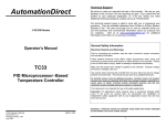
1
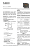
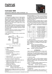
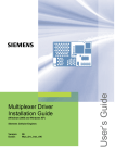
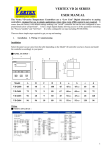
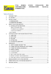
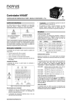
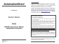
AutomationDirect
Technical Support
We strive to make our manuals the best in the industry. We rely on your
feedback to let us know if we are reaching our goal. If you cannot find the
solution to your particular application, or, if for any reason you need
additional technical assistance, please call us at 770-844-4200.
Our technical support group is glad to work with you in answering your
questions. They are available weekdays from 9:00am to 6:00pm Eastern
Standard Time. We also encourage you to visit our website where you
can find technical and non-technical information about our products and
our company.
Visit us at www.automationdirect.com for additional
information and FAQ’s on our process controllers.
1/16 DIN Series
General Safety Information
Operator’s Manual
Electrical Hazards and Warnings
Prior to connecting the controller, read the user’s manual for proper connection
and operating information.
Follow National Electrical Code (NEC) safety requirements when wiring and
connecting a power source and sensors or other devices to the controller. Failure
to do so could result in injury, death or damage to equipment and property.
TC33
Make sure the proper input voltage is applied to the controller. Improper voltage
will result in damage to the unit.
PID Microprocessor - Based
Temperature Controller
Use caution when removing the controller from its case, there may be live voltage
present at the terminals. This should only be done by a qualified technician.
All terminal screws must be tightened securely. Terminal screws not properly
secured can cause an electrical short that may damage property, equipment or
cause injury or death. Terminal screws improperly secured may fall into
equipment causing possible damage to property or equipment.
This instrument is not intended for use in life safety applications.
Important: For applications where physical injury or equipment damage might
occur in the event our product fails, we recommend the installation of
independent safety equipment with its own independent sensor that will shut
down the process.
TC33 Operator’s Manual
Manual Rev. 2.2
Firmware Version 1.40
July 2003
Made In USA
Important: Firmware version of controller must match the version indicated
on the bottom front cover of this manual.
1
TC33 Temperature Controller
1/16 DIN Series
TC33 Operator’s Manual
Manual Rev. 2.2
Firmware Version 1.4x
Table of Contents
Description
TC33
1/16 DIN - PID Autotune
Temperature Controller
Page
1. Main Features …………………..…………………………………….… 3
2. Specifications ………………………...……….……………….………..3
Input ………..………………………………………………..…….. 4
PID Control …….…………………….…………………..….…….. 4
Output ……….….…………………………………..……………... 4
2.1 Main Dimensions ……..…………………………………..…….…... 4
3. Operation .…………….…………………………………...……………. 5
3.1 General Electrical Connections ……………………………………6
3.2 Power Wiring ………………………………………..………………. 6
3.3 Input Wiring …………………………..………………………………7
3.4 Standard Relay Outputs …………….………..…………….………7
3.5 Sourcing 4-20mA Output Wiring ……..……..……………………..7
3.6 Panel Assembly …….…..…………………………………….……..8
3.7 Error Messages …..………………………………………….………8
4. Menu System ……………………………………………………………...8
4.1 Initial Startup ……………...…………………………………….……9
4.2 Set Up Cycle Parameters …..…………...……………………….…9
Cycle Menu ………………………..…………………………..…..9
4.3 Digital Serial Number Access …..…………………………….…….9
5. Configuration ……………..………………………………………..…….. 10
5.1 Cycle 1 – Operation …..……………………………………………..10
Ramp & Soak ……………………………….……………….…….11
5.2 Cycle 2 – Tuning & Alarms ……..……….………...………………..12
5.3 Cycle 3 – Input Configuration …...………………………………….13
Alarms Configuration …….…………….…………….……………13
Table 1 – Alarm Functions ….……………………….….…..……14
5.4 Cycle 4 – Calibration …………..……….…………………………...16
5.5 PID Auto-Tune Operation ………...…….………………………...…17
5.6 PID Manual Tuning ………………………………………………….18
Table 2 – PID Manual Tuning ….………………………………..19
Quick PID Set Up Reference …………………………………..……....…. 19
Notes ……………………………………………..…………… ……………...21
Configuration Sheet ………………………………………………………... 22
1. MAIN FEATURES
•
•
•
•
•
•
•
•
•
•
•
•
•
•
•
•
•
2. SPECIFICATIONS
•
•
•
•
•
•
•
2
Temperature multi-sensor input without hardware change.
Accepts thermocouples J, K, S, T, N, E, R, and RTD-Pt100.
Dual Display: PV (red) and SV (green).
Selectable ºF/ºC temperature.
RTD-Pt100 with 1º temperature resolution: -328 to 986 ºF (-200 to 530 ºC), and
0.1º temperature resolution: -199.9 to 986.0 ºF (-199.9 to 530.0 ºC).
Input sample rate: 10 reading per second (100 ms).
Isolated 4 to 20mA linear control output, optional.
Ramp and Soak: one controlled ramp and one timed soak are standard.
Auto-tuning PID control, or manual PID control, or ON/OFF control with
hysteresis adjust.
Sensor break protection in any condition.
Independent alarm hysteresis adjust.
Easy-to-set programming menu.
Firmware version displayed during power up.
Digital serial number.
High impact ABS enclosure.
Dimensions: 48x48x106mm.
Power: 90 to 260Vac, 50/60Hz.
Dimensions: 48 x 48 x 106mm (1/16 DIN) Approximate weight: 200g max.
Panel cut-out: 45.5 x 45.5mm (± 0.3mm)
Terminal connection: screws, accepting 16 to 24 AWG wires or 6.3 mm fork
lugs.
Power: 90 to 260Vac, 50/60Hz, Consumption: 7VA max.
Operating environment: 0 to 50°C (32 to 122°F), humidity: 10 to 85% RH, noncondensing.
Flame-Retardant ABS Plastic Case.
Warm-up time: 15 minutes max.
3
INPUT
•
•
•
•
Keypad selection of input type (refer to Cycle 3).
Display resolution: 0.1ºF/C or 1ºF/C (RTD-Pt100).
Input sample rate: 10 per second (10Hz).
Accuracy: Thermocouples J, K, T, N, E: 0.2% of span, ±1ºC, ±1 digit.
Thermocouples S, R: 0.25% of span, ±3ºC, ±1 digit.
Pt100: 0.2% of span, ±0.5ºC, ±1 digit.
•
Input impedance:
•
Pt100 measurement:
3. OPERATION
Operator Interface
Thermocouple: >10MΩ
DIN 43760 standard (α=0.00385).
3-wire circuit, cable resistance compensation.
Excitation current: 170µA.
PID CONTROL:
•
•
•
•
•
•
User-selectable as: ON-OFF w/ adjustable hysteresis, or manual P, PI, PID and
PID-Autotune.
Proportional Band (Pb): 0 = ON/OFF control; or 1% to 500% of maximum input
span.
Integral (Ir): 0 = off; or 0.01 to 25.00 rep/minutes
Derivative (Dt): 0 = off; or 1 to 250 seconds.
Cycle-Time: 0.5 to 99.9 seconds (for PWM-PID output control).
PID-Autotune: start from the front panel.
OUTPUT: model TC33-1100-AC:
•
•
Control – C LED: indicates that the controller is active, with control. If there is
a control output programmed as PWM or ON/OFF, the output
LED will reflect the actual state of the output (ON or OFF).
If there is a Linear 4-20mA control output, the LED will be
continuos ON.
One isolated Linear Control sourcing 4-20mA output @ 500 ohms max. load.
Two SPST Relay Alarms (without contact suppression):
Resistive: 3A @ 250VAC / 3A @ 125VAC / 3A @ 30VDC
Inductive: 2A @ 250VAC / 2A @ 30VDC
Dielectric Strenght: 750Vrms between open contacts (at sea level for 1 min.)
Auto-Tune – AT LED: indicates that the controller is in Auto-Tune mode,
(LED On = Auto-Tune active).
Alarm 1 – AL1 LED: indicates the status of the alarm, (LED On = alarm active).
Alarm 2 – AL2 LED: indicates the status of the alarm, (LED On = alarm active).
2.1 MAIN DIMENSIONS, AND PANEL CUTOUT:
6 mm
100 mm
SET UP key: used to set up menu cycles.
Decrease key: used to change parameter values.
45.2 mm to 45.8 mm
AT
Panel Cutout
A1
SET
UP
(Not to scale)
45.2 mm to 45.8 mm
AutomationDirect
A2
Process Display - PV: shows the PV (Process Variable) value, and used when
configuring the parameters of the controller.
Setpoint Display – SV: shows the SV (Setpoint Variable) value, and used when
configuring the parameters of the controller.
One isolated Pulsed DC Output Control (12Vdc pulsed @ 15mA max.).
One SPST Relay Alarm (without contact suppression):
Resistive: 3A @ 250VAC / 3A @ 125VAC / 3A @ 30VDC
Inductive: 2A @ 250VAC / 2A @ 30VDC
Dielectric Strenght: 750Vrms between open contacts (at sea level for 1 min.)
OUTPUT: model TC33-2010-AC:
•
•
(Figure 2)
Increase key: used to change parameter values.
When the controller is initially energized, the firmware version is displayed
for approximately 4 seconds, after which the controller starts normal
operation. The values of PV (temperature), and SV (setpoint) are displayed
and the outputs are enabled after 6 seconds.
(Figure 1)
4
5
Before the controller is ready to be used in a given process, it requires some basic
configuration, such as:
• Input Type (T/C, or Pt100) at the tYPE prompt, section 5.3 (page13).
• Output Configuration (control, alarms) at (ntr prompt, section 5.3 (page13).
• Setpoint Variable SV.
• PID parameters (or hysteresis for ON/OFF control), see Cycle-2 (page12).
Other functions, including alarms, ramp to soak, etc., may be useful for a better
system performance.
3.3 INPUT WIRING: RTD-PT100 AND THERMOCOUPLE:
Sensor Input
Thermocouple
Sensor Input
RTD - Pt100
1
2 3
2
(Figure 5)
3.1 GENERAL ELECTRICAL CONNECTIONS:
Model TC33-2010-AC
Model TC33-1100-AC
TC
1
Rtd
2
3
1
3.4 OUTPUTS:
2
3
13
14
Notes: 1) For Thermocouple Sensors use appropriate compensated
thermocouple wires.
2) Use copper conductors rated for at least 75 ºC (except on T/C).
TC
Rtd
3
TC3X
TC3X
Two SPST Relay Output
(TC33-2010-AC)
One Pulsed & One Relay
(TC33-1100-AC)
9 10 11 12
9 10 11 12
15
7
8
Power In
90~260 Vac
9 10 11 12
Relay
AL-2
7
Relay
CONTROL
or AL -1
8
Power In
90~260 Vac
9 10 11 12
Relay
AL-2
+
ALM-2
ALM-1
or
CONTROL
Relay
AL-2
+
CONTROL
(ON/OFF or PID)
(Figure 6)
CONTROL
3.5 SOURCING 4-20MA OUTPUT WIRING:
(Figure 3)
Linear 4-20mA Sourcing Output
(TC33-2010-AC)
3.2 POWER WIRING:
AC Voltage Power Wiring
4~20mA
Linear
Control
7
8
Fuse
Power In
90~260 Vac
50/60Hz
-
13
14
15
(Figure 7)
200mA - Slow Blo
Note: The installation of fuse is optional, depending on level of protection required.
(Figure 4)
6
NOTE: All terminal screws must be tightened securely. Terminal screws not
properly secured can cause an electrical short that may damage property,
equipment or cause injury or death. Terminal screws improperly secured may fall
into equipment causing possible damage to property or equipment.
7
PANEL ASSEMBLY:
4.1 INITIAL STARTUP:
First remove the mounting clamp and insert the controller into the panel cut out.
Place the unit into the panel cut out and slide the mounting clamp from the rear to
a firm grip at the panel.
The internal circuitry can be fully removed from the housing without disconnecting
any wiring. By using the thumb, just press the tab in the lower part of the front
panel, grab the front panel firmly and pull the front face and circuitry from the
housing.
Warning: Use caution when removing the controller from its case, there may
be live voltage present at the terminals. This should only be done by a
qualified technician. It is recommended that power to the controller be
disconnected prior to removing the controller from the case.
3.6 ERROR MESSAGES:
The connection and configuration errors for most of the problems encountered in
using the controller are shown below. A final revision of parameters will save time
and further losses.
Error messages are displayed to help the user to identify possible problems.
: Process temperature is below the selected sensor range.
: Process temperature is above the selected sensor range
When the controller is initially energized the Firmware version is displayed for
approximately 4 seconds in the PV display after which the controller reverts to
normal operation mode or Operation Cycle. This is SET UP Cycle-1. The upper
display, PV, shows the Process Variable (temperature) and the lower display, SV,
shows the Set Point Variable in this cycle. The controller remains in this cycle
while under normal operation.
Important: Firmware version of controller must match the version indicated
on the bottom front cover of this manual.
4.2 GENERAL SETUP CYCLE PARAMETERS:
The cycles need only to be accessed when a change of parameters is necessary
(except for Set Point change). To reach the other parameters the user must keep
the SETUP key pressed for about 4 seconds. After this time the controller will
show the first parameter of the next cycle, i.e., Atvn for Cycle-2. By keeping the
SETUP key pressed for another 3 seconds the next cycle will be accessed.
Release the SETUP key when the desired cycle is reached. Press the SETUP key
once to go to the next menu parameter in the cycle. The PV display will show the
parameter and the SV display will show the value in the parameter.
To change the value of the parameter press the
value is reached.
or
keys until the desired
Cycle Menu System
: Controller or sensor error. Example:
•
•
Broken thermocouple or Pt100.
Pt100 badly connected, short-circuited or high cable resistance.
4. MENU SYSTEM
The Parameter Menu System is organized into four basic cycles. This is shown in
the chart below:
After the last parameter in one level is reached the controller returns to the
Operation Cycle and the display will indicate the measured temperature.
CYCLE
ACCESS
Free access parameters
1- Operation
2- Tuning and Alarms
Reserved access
3- Input Type and Configuration
4- Calibration
NOTE: The display will also go back to the measured temperature whenever
the display is inactive for 20 seconds or more.
8
4.3 DIGITAL SERIAL NUMBER ACCESS:
To read the controller’s serial number (8 digits), hold down the
key during the
power up. The first four digits will appear in red on the top display, and the second
four digits will appear in green on the bottom display.
The serial number is recorded in the factory and cannot be changed.
9
5. CONFIGURATION
RAMP & SOAK
Prior to first operation, the controller should be fully configured. After the controller
is energized and is in normal operation mode press the SET UP key several times
until the rvn parameter is displayed. Using the
or
keys change the value to
0, this disables all outputs. After disabling all of the outputs the user can now set
the basic parameters such as Input Type (“TYPE”) in Cycle-3, the desired control
Set Point (“ SP “) in Cycle-1, the Alarm Set Points (“A1SP” and “A2SP”) in Cycle2, etc. The first parameter that needs to be programmed is the Input Type
(type) in the Input Cycle, Cycle-3 (see section 5.3 page 13).
“Rate” (ramp) function:
After all parameters are set, enable the controller operation by changing the rvn
parameter back to 1. This enables all outputs. The following menu Cycles give
information on programming each parameter.
All parameter settings are stored in non-volatile memory after moving to the next
parameter or if the value has not been changed within a 20 second period.
(RED display)
SV Indication
(GREEN display)
Rate
(ramp)
T Sp
(soak)
Rvn
“ t SP” (soak) function:
When SP is reached the temperature is leveled at this point for 1 to 9999 minutes
as programmed at the “t SP ” prompt. After the programmed period (t SP) the
output control is turned Off. To restart control set 1 at the “rvn” prompt.
Setting value 0 at “t SP” (disable the soak function) defines an infinite length
soak profile (default = 0).
Note 1: Setting value 0 at “t SP”, if “rate function” (ramp) is disabled.
5.1 CYCLE 1 – OPERATION:
PV Indication
This function makes the process temperature rise gradually (ramp) from the
starting point (present PV) to a final specified value in setpoint (SV), creating a
heating ramp. The user defines the rate of rise in degrees per minute (from 0.1 to
100.0°F or °C / minute) at the “rAtE” prompt.
To disable the ramp function set 0.0 at the “rAtE” prompt (default = 0.0).
CYCLE 1
PV AND SV INDICATION:
PV: The status display shows the present value of PV
(Temperature).
SV: Adjust the desired temperature value (Setpoint) for the
or
within the limit defined in
controlled system by pressing
the parameter “spxl“ in Cycle-3.
TEMPERATURE RATE OF RISE: The user defines the rate of
temperature rise from the starting temperature to the value set in
SV. Rate is defined in °F or °C per minute (programmable
range: 0 to 100.0°/minute). Default: 0.0
See page 11 for a description of this.
“To disable the ramp function set: Rate = 0.0 ”.
TIME FOR SOAK: Time in minutes in which the temperature will
remain at the selected t sp (soak setpoint in SV display). (Set: 0
to 9999 minutes). Default: 0
See page 11 for a description of this.
Note: Setting value 0 at “t SP”, if “rate function” (ramp) is
disabled.
“To disable the soak function set: t SP = 0”.
RUN: At this prompt the user sets the control output and alarms
to active or to inactive. Default: 1
0 - inactive outputs
1 - active outputs
10
Note 2: After a power failure the controller will resume ramp to soak execution at
the equivalent previous ramp point. If the process temperature is the same as the
setpoint, SV, (no temperature drop) the controller will repeat the soak segment.
Temperature
Soak
SP
Ramp
PV
Time
(Figure 8)
Single Ramp - The controller allows the temperature to gradually rise from an
initial value to a final specified value in setpoint, creating a heating ramp. The user
may determine the rising time of the ramp on the controller, which defines the
velocity of the temperature in degrees per minute.
11
5.2 CYCLE 2 – TUNING AND ALARMS:
Atvn
CYCLE 2
AUTO-TUNE: Activates the auto-tuning of PID parameters.
0 - Auto-tune is off (led “AT” = off)
When set to 0 the controller is in Manual PID control or ON/OFF
control (pb = 0 ).
1 - Auto-tune is on (led “AT” = on)
When set to 1 the controller is in PID Auto-tune control.
Default: 0
5.3 CYCLE 3 – INPUT TYPE, AND OUTPUT CONFIGURATION:
CYCLE 3
INPUT TYPE: Selects the input sensor type to be connected to the
controller. Default: 1 (T/C Type K)
“This is the first parameter to be set.”
Type
PROPORTIONAL BAND: 0 to 500% of maximum input span.
Pb
Ir
When this parameter is set to zero (Pb= 0 ) and atvn is set to 0 the
control action is ON/OFF output mode, with control hysteresis adjust.
Default: 10.0
INTEGRAL RATE: 0.00 to 25.00 rep/min = Integral time constant in
repetitions per minute (Reset). Default: 0.00
This constant is not used when controller is set to ON/OFF action
(Pb= 0 ).
Dt
(t
DERIVATIVE TIME: 0 to 250 = Derivative time constant in seconds.
This constant is not used when controller is set to ON/OFF action
(Pb= 0 ).
Default: 0
is displayed, and the control output is turned off.
Vnit
A(t
CYCLE TIME: Pulses in period per second. This term is only used when
the controller is set to PID action.
Default: 0.5 (in seconds)
KySt
CONTROL HYSTERESIS: Is the hysteresis for ON/OFF control (set in
temperature units). Default: 0
This parameter is only used when the controller is in ON/OFF mode
(Pb= 0 ).
A1SP
SETPOINT value for ALARM 1: Set-point for alarm 1
Default: 610
A2SP
SETPOINT value for ALARM 2: Set-point for alarm 2
Default: 610
12
0 - T/C type J: -58 to 1400°F ( -50 to 760°C )
1 - T/C type K: -130 to 2498°F ( -90 to 1370°C )
2 - T/C type S: 32 to 3200°F ( 0 to 1760°C )
3 - RTD-Pt100 with 0.1° resolution: -199.9 to 986.0°F ( - 199.9 to 530.0°C )
4 - RTD-Pt100 with 1° resolution: -328 to 986°F ( -200 to 530°C )
5 - T/C type T: -148 to 752°F ( -100 to 400°C )
6 - T/C type E: -22 to 1328°F ( -30 to 720°C )
7 - T/C type N: -130 to 2372°F ( -90 to 1300°C )
8 - T/C type R: 32 to 3200°F ( 0 to 1760°C )
NOTE: In case of sensor break or failure an error " Erro" message
(ntr
TEMPERATURE UNIT: Selects display indication for degrees
Celsius or Fahrenheit. Default: 0
0 - degrees Celsius ( °( );
1 - degrees Fahrenheit ( °f );
ACTION CONTROL: Default: 0
0 - Reverse action. Generally used for heating.
1 - Direct action. Generally used for cooling.
CONTROL OUTPUT CONFIGURATION:
0 - Sets Control output (ON/OFF or PWM - PID) on terminals
13-15 (4-20mA pulsed), with Alarm-1 on terminals 11-12, and
Alarm-2 on terminals 9-10. See atvn and pb for ON/OFF and
PID control description in Cycle-2, page 12.
Note: 4-20mA will operate as PWM in the 4mA or 20mA state,
(This is not a linear 4-20mA output control in this configuration).
1 - Sets Control output (ON/OFF or PWM - PID) on terminals 11-12,
and Alarm-2 on terminals 9-10.
2 - Sets Linear 4-20mA PID Control output on terminals 13-15,
with Alarm-1 on terminals 11-12, and Alarm-2 on terminals 9-10.
NOTE: • Controller model TC33-1100-AC: Default = 1
• Controller model TC33-2010-AC: Default = 2
SpLl
SETPOINT LOW LIMIT: Sets the lower range for SV and PV
indication. Default: -150
Spxl
SETPOINT HIGH LIMIT: Sets the upper range for SV and PV
indication. Default: 1370
13
A1fv
A2fv
A1xY
A2xY
ALARM 1 Function: (code 0 to11): Refer to Table 1 page 14 for
function description and respective codes to set at this prompt.
Default: 0
ALARM 2 Function: (code 0 to11): Refer to Table 1 page 14 for
function description and respective codes to set at this prompt.
Default: 0
Dif-SPAL+
SV
(SV)+(SPAL+)
Differential
(Band Alarm)
4
Dif-SPAL-
ALARM 1 HYSTERESIS: Defines the differential range between the
PV value at which the alarm is turned on and the value at which it is
turned off. Default: 0
ALARM 2 HYSTERESIS: Defines the differential range between the
PV value at which the alarm is turned on and the value at which it is
turned. Default: 0
CODE
(SV)+(SPAL -)
Input Sensor
Error
5
Low Alarm
0
SPAL
Alarm Functions
“With alarm inhibition
at power-up”
7
8
9
10
11
SV
2
Dif-Low SPAL-
PV
(SV)+(SPAL -)
(SV)+(SPAL+)
3
Dif-High SPAL-
PV
(SV)+(SPAL -)
Low alarm disabled at power-up
High alarm disabled at power-up
Differential low limit alarm disabled at power-up
Differential high limit alarm disabled at power-up
Differential alarm disabled at power-up
SV
Low Alarm: Activates at present value, independent of main setpoint.
process-alarm activates at and below alarm setting.
Low
High Alarm: Activates at present value, independent of main setpoint.
process-alarm activates at and above alarm setting.
High
Differential Low: Activates at present deviation (negative or positive) value from
main setpoint. Low deviation-alarm activates below alarm setting. Figure 9(a) on
page 16 gives a graphical description of this.
PV
SV
” t sp “ on Cycle 1)
Alarm Functions:
PV
(SV)+(SPAL +)
Dif-High SPAL+
Alarm turn On (“Time for Soak”, see function
( where SPAL means: A1SP and A2SP)
SPAL
SV
Differential High
(Deviation High)
6
1
Dif-Low SPAL+
Differential Low
(Deviation Low)
End of Soak Timer
PV
High SPA L
High Alarm
(High Temperature
Alarm)
is too high.
PV
(Low Temperature Alarm)
Alarm is ON whenever:
• Temperature is below selected range.
• Temperature is above selected range.
• Thermocouple or Pt100 is broken.
• Pt100 is shorted, badly connected or wire impedance
ACTION
Low SPAL
PV
SV
Table 1 – Alarm Functions
Table 1 shows each alarm function operation with their respective code.
TYPE
PV
Differential High: Activates at present deviation (negative or positive) value from
main setpoint. High deviation-alarm activates above alarm setting. This is
represented in Figure 9(b) on page 16.
( where SPAL means: A1SP and A2SP)
Differential: Activates when the process exceeds a specified band-alarm centered
around the main setpoint. See Figure 9(c) on page 16.
14
15
Inhibition at power-up: Alarm blocking at power-up inhibits the relay alarm from
activating when the unit is first energized. The alarm will only trip after the process
variable reaches a new alarm situation.
Alarm Hysteresis: Defines the differential range between the PV value at which
the alarm is turned on and the value at which it is turned off.
5.4 CYCLE 4 – CALIBRATION LEVEL:
NOTE: All input and output types are factory calibrated. This cycle
should only be accessed by experienced personnel. If in doubt do
keys in this cycle.
or
not press the
Inl(
Alarm Functions (Graphic):
Input Low
Calibration
InK(
Process
Process
SV+(SPAL-)
SV
SV
SV+(SPAL+)
AL
on
AL
on
(a)
INPUT HIGH CALIBRATION. Sets the sensor input circuit gain or
high calibration. A signal simulator should be used to inject a high
value signal to properly adjust the offset.
(j L
AL
on
time
Dif-Low SPAL -
Input High
Calibration
SENSOR OFFSET CALIBRATION. Sets the temperature sensor
low calibration (offset). The display shows only the corrected
temperature and not the offset added. A signal simulator should be
used to inject a low value signal to properly adjust the offset.
AL
on
time
COLD JUNCTION OFFSET CALIBRATION: Sets the cold junction
Cold Junction °C offset calibration. A good thermometer or a temperature simulator
Low Calibration should be used to properly adjust this parameter.
Dif-Low SPAL+
PID AUTO-TUNE OPERATION:
Process
Process
SV+(SPAL+)
SV
SV
SV+(SPAL-)
AL
on
AL
on
time
Dif-High SPAL+
During auto tune the temperature is controlled in ON/OFF mode until is reaches
the programmed Set Point (SV). Depending on process characteristics large
oscillations above and below SV may occur and auto tuning may take several
minutes to be concluded.
(b)
time
Dif-High SPAL-
The standard procedure is as follows:
•
Disable all outputs at the rvn prompt in the Operation Cycle (Cycle-1) by
selecting 0.
•
Disable the rate and t sp in Cycle-1 by selecting 0 for each.
•
Enable auto-tuning at the atun prompt in the Tuning Cycle (Cycle-2) by
selecting 1.
•
Enable all outputs at the rvn prompt in Cycle-1 by selecting 1.
During auto-tune the AT LED is ON. Once auto-tune is complete, the AT LED
turns OFF.
Process
SV+(SPAL+)
Process
AL on
SV
SV
SV+(SPAL+)
SV+(SPAL- )
AL on
Dif SPAL+
The recommended procedure is as follows:
•
Follow the procedure above except, program a setpoint 10 – 15% below the
final desired value.
•
After auto-tune is complete (the “AT” LED is off), change the setpoint to the
final desired value.
SV+(SPAL- )
AL on
time
time
(c)
(Figure 9)
16
Dif SPAL-
If auto-tuning results are not satisfactory, refer to section 6.5 and Table 2 for
manual fine tuning procedure.
NOTE: Certain processes behave in very irregular manners. In these cases,
control type “On/Off with hysteresis adjust” is recommended.
17
5.5 PID MANUAL TUNING
TC33 Quick PID Setup Reference
Table 2 - Suggestions for manual tuning of PID parameters
PARAMETER
RESPONSE
SOLUTION
Proportional Band
Slow Response
Decrease
Proportional Band
Large Oscillation
Increase
Integral Rate
Slow Response
Increase
Integral Rate
Large Oscillation
Decrease
Derivative Time
Slow Response or Instability
Off (Dt= 0)
Derivative Time
Large Oscillation
Increase
The operator may choose to tune the controller manually for optimum process
performance once all parameters are set. This can be achieved by using Table 2
or by determining the values for the proportional band pb, integral rate IR, and
derivative time dt. The procedure below should only be implemented on
processes that will not be damaged by large fluctuations in the process
variable.
Step 1. Disable all outputs in Cycle-1 by changing rvn to 0. Change the setpoint
to the desired process variable (PV) in the Operation Cycle. This value should be
below (PV) if overshoot will cause damage to the process.
Key and Display Functions
PV display: Indicates the
process temperature, program
parameters, sensor errors.
C Led: Indicates that the
Control Output is energized.
AT Led: Indicates that the
controller is in AutoTune mode.
A1 Led: Indicates the status
of alarm 1.
A2 Led: Indicates the status
of alarm 2.
AT
SV display: Indicates the
setpoint, program parameter
values, and alarm codes.
A1
A2
SET
UP
SET UP: Used to move
forward through a menu Cycle.
Used to advance to the next
Cycle when pressed and held
for 4 seconds.
: Used to increase the value
of the displayed parameter.
: Used to decrease the value
of the displayed parameter.
Set Up Cycle Parameter Access
Step 2. Make sure pb is set to 0 in Cycle-2, page 13. This places the controller in
ON/OFF control.
Step 3. Enable all outputs by changing rvn to 1 in Cycle-1. Once the outputs are
enabled the process variable (PV) will approach and eventually overshoot the
setpoint (SV). At this point the operator should note the following values (see
Figure 10):
•
The value from the highest point of overshoot to the lowest point of
undershoot, X.
•
The cycle time of the oscillation, T.
Using the following information and the values above the operator can determine
the PID setting for the process:
•
•
•
= X ÷ scale range x 100
= T = cycle repetitions per minute
=T÷6
Pb
Ir
Dt
P V
TC33 Quick Set UP
S V
X
T
tim e
(Figure 10)
18
This quick reference setup is intended to be used by experienced users that are
familiar with the TC33 set up menu or those that only need basic PID operation.
This guide will show how to configure the input, output control and basic alarm
function. For Detailed programming information refer to the Table of Contents to
find the required instructions for a particular function. Follow these steps below:
19
1.
Operation: Connect power input to the proper terminal conections. See page
6 sections 3.1 & 3.2. After power-up the controller is in the Operation Cycle
(Cycle-1). Refer to Cycle Menu on previous page. Disable all outputs by
pressing the SET UP key until rvn is displayed in the PV display. Press the
or
keys until 0 is displayed in the SV display. The controller outputs
are now disabled. To move from one Cycle menu to the next press and hold
the SET UP key for 4 seconds. The first parameter in the Cycle will be
displayed in the PV display.
10. Alarm Set Points: Press the SET UP key two more times in Cycle-2 until
or
keys to increase or
a1sp is displayed in the PV display. Press the
decrease Alarm 1 set point in the SV display to the desired value. a1sp
should be programmed only if the Output Configuration, [ntr (in 5. above), is
set to 0 or 2. When set to 1 this output is used for control. Refer to Cycle 3
page 13. Press the SET UP key again and a2sp is displayed in the PV
display. Follow the same steps if Alarm 2 is configured. Press the SET UP
key to go back to the Operation Cycle (Cycle-1).
2.
Input Type: From the Operation Cycle press and hold the SET UP key for
approximately 7 seconds to advance to the Input Cycle (Cycle-3), type will be
displayed in the PV display. Select the input type from section 5.3 on page 13
or
using the
keys. For example, 0 shown in the SV display designates
a type J thermocouple for the input sensor.
11. Enable Process Outputs: In the Operation Cycle press the SET UP key until
or
rvn is displayed in the PV display. Press the
keys to change the
1
SV value to . All outputs are now enabled and the controller is fully
operational in PID auto tune mode.
3.
Temperature Unit: While in Cycle-3 press the SET UP key until vnit is
or
keys to select the
displayed in the PV display. Press the
temperature unit in the SV display, 0 for °C or 1 for °F.
4.
Control Action: Press the SET UP key again in Cycle-3 until act is
or
keys to select the control
displayed in the PV display. Press the
action in the SV display, 0 for reverse action (generally used for heating) or 1
for direct action (generally used for cooling).
5.
Output Configuration: Press the SET UP key again in Cycle-3 until [ntr is
displayed in the PV display. Select control output configuration 0,1, or 2 in
or
keys. See section 5.3 on page 13 for a
the SV display using the
description of these configurations.
6.
Alarm Functions: Press the SET UP key 2 more times in Cycle-3 until a1fv
is displayed in the PV display. a1fv should be programmed only if the Output
Configuration, [ntr (in 5. above), is set to 0 or 2. When set to 1 this output is
used for control. Refer to Cycle 3, page 13. Select the alarm function from
Table 1 on page 14. After this alarm function is chosen press the SET UP key
again to move to a2fv and follow the same steps if a second alarm is desired
based on the control action set above in 5. Press the SET UP key again and
the controller reverts to Cycle-1.
7.
Set Point: Program the set point in Cycle-1 by pressing the
or
to increase or decrease the set point (SV Display) to the desired value.
8.
Auto Tune: Press and hold the SET UP key for 4 seconds to advance to the
Tuning Cycle (Cycle-2), atvn will be displayed in the PV display. Press the
or
keys until the number1 is displayed in the SV display. The controller
is now set for Auto Tune.
9.
Cycle Time (optional): Press the SET UP key several times until [t is
displayed in the PV display. The default cycle time is factory set for 16
or
seconds. If a different cycle time is desired then press the
keys to
increase or decrease the value shown in the SV display.
20
NOTES:
keys
21
TC33
Configuration Sheet
Name:
Date:
Part#:
Project:
Main Setpoint (SV):
Cycle 3
CONFIGURATION
Type
Unit
Act
[ntr
Spkl
A1fu
A2fu
Cycle 2
ALARMS
Atvn
Pb
Ir
Dt
Ct
Kyst
A1sp
A2sp
Cycle 1
OPERATION
RATE
T SP
RVN
Default CODE/VALUE CHARACTERISTICS / FUNCTION
1
0
0
2
1370
0
0
Default CODE/VALUE
CHARACTERISTICS / FUNCTION
0
10.0
0.00
0
0.5
0
610
610
Default CODE/VALUE
0.0
0
1
22
CHARACTERISTICS / FUNCTION