1
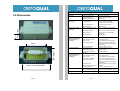
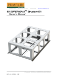
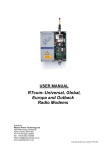
Contents
Series 130
Ozone Controller
User Guide
1. Ozone Controller Components
2. Setting Up the Ozone Controller
1
2
2.1 Monitor Assembly
2.2 Power Requirements
2.3 External Control Wiring
2.4 Removing and Replacing the Sensor Head
2
2
3
3
3. Modes of Operation
4
3.1 Warm up
3.2 Operating in Low or High Ozone Environments
3.3 Operating as a Controller
3.4 Dual Alarm mode
3.5 Summary of LED Indicators
3.6 Inlet Port Maintenance
3.7 Dip Switch Settings
4
4
4
6
7
7
8
4. Specifications – Series 130
5. Dimensions
6. Troubleshooting
7. Appendix
9
10
11
12
7.1 Copyright
7.2 Statement of Compliance
7.3 Warranty
7.4 Guidelines on How to Measure Ozone
12
13
14
16
Version 1.1 20.02.10
1.0 Ozone Controller Components
Series 130 Ozone Controller
Distributor:
Wessex Power Technology Ltd, Dorset
Tel: +44 (0)845 520 0303 | Fax: +44 (0)845 520 0304
Email: [email protected] | www.wessexpower.co.uk
-
-
The following components are supplied with the Series 130 Ozone
Controller:
• Series 130 controller assembly inside an FRP enclosure
• Ozone sensor head plugged in
• User guide
• Wall fixing brackets
•
Eight pole M12 male cable connector
Please check that all these components have been supplied
and contact your dealer or Aeroqual on email at:
[email protected] if any of the components are missing.
- 1 -
2.0 Setting up the Ozone Controller
2.3 External Control Wiring
2.1 Monitor Assembly
The M12 ‘8-pole’ connector configuration, viewed from the outside of the
enclosure is as shown below. (Note the centre pole is not used)
The Series 130 Ozone Controller comes pre-assembled and
ready for use. It is however recommended that the installer
carries out the following:• Open the plastic enclosure by loosening the four screws and
remove the lid.
• Ensure that the sensor head is firmly located into the location
slot in the metal mounting plate and that it is also firmly
located between the plastic inlet and outlet nozzles, which
penetrate through the sides of the enclosure. Should this not
be the case, then follow the instructions for removing and
replacing the sensor head on the following page.
• The unit is factory set with the dip switches set to operate in
alarm mode with the alarm set points at 0.100ppm and
0.300ppm. If this is not suitable, follow the instructions for resetting these controls on page 8.
• Wire up the male end of the M12 cable connector and test the
system.
ON / OFF LED
Power Signal (5V)
16-28VDC (in)
Volt-free Contacts 2
GND
2.4 Removing and Replacing the Sensor Head
“A”
“B”
“E”
2.2 Power Requirements
The Series 130 controller is designed to be powered by a 24VDC,
power supply (user supplied). The permissible voltage range is
between 16VDC and 28VDC.
Ensure that the power supply to the unit is sized to account for
the voltage drop across the connecting cable so that it delivers at
least 16VDC(minimum) to the Series 130.
The unit does not have an On/Off switch and is activated when
power is supplied to the unit. Before powering up the unit, ensure
that all the necessary wiring connections are correctly in place.
NOTE: Do not insert or remove the sensor head while power
is being supplied to the unit.
“C”
•
•
•
•
•
-
2
Volt-free Contacts 1
-
“D”
Undo the four lid screws, remove lid and view the interior of the
enclosure as shown above.
Unscrew and remove the inlet & outlet nozzles “A” & “B” as well as
the corresponding lock-nuts “C” & “D”.
Remove the sensor head “E”.
Now replace the sensor head (keyed to fit one way only) and reposition nozzles “A” & “B”.
Finally, tighten lock-nuts “C” & “D”.
-
3
-
3.0 Modes of Operation
3.3 Operating as a Controller
The Series 130 can operate either as a controller or an alarm switch.
These modes control the two on-board relays in different ways. The
required operating mode is selected via dipswitches as outlined
below.
Set the mode dip switch (B-2) to position "off". Set the low (“C”)
and high (“A”) control limits [‘dead band’] by configuring the dip
switches as per the dip switch table on page 8. When in control
mode relay 1 operates as per the table and diagram below. Relay
2 is opposite.
3.1 Warm up
Warm up the controller to burn off contaminants on the
sensor. During warm up the LED will flash green slowly. If the
controller has not been run for a few days it may take an hour or
two to reach full accuracy.
3.2 Operating in Low or High Ozone Environments
The controller can operate either low or high ozone concentration
sensor heads by setting the dip-switch B-1 to the “off” position for
a low concentration head and “on” for a high concentration head.
High/ Low conc (B1)
Control/ Alarm (B2)
High Limit
A
Low Limit
B
Controller mode LED, Relay and Status
Ozone
Relay 1
Relay 2
below low
limit
ORANGE
LED
closed
open
between
low and
high limits
GREEN
Above high
limit
Sensor fault
RED
*closed if ozone
concentration
rising
*open if ozone
concentration
falling
open
*open if ozone
concentration
rising
*closed if ozone
concentration
falling
closed
open
closed
open
open
Settings fault
C
RED
FLASH
ORANGE
FLASH
Concentration
High Setpoint
Software
Dead Band
Relay open
(de-energised)
Relay closed
(energised)
[Relay 2 is opposite]
[Relay 2 is opposite]
Low Setpoint
Time
LED Color
-4 -
-
5
-
3.4 Dual Alarm Mode
3.5 Summary of LED Indicators
Set the mode dip switch (B-2) to the dual alarm switch position – "on".
Set the low (“C”) and high limits (“A”) by configuring the dip switches as
per the dip switch table on page 8. In this mode the low limit dip switch
controls Relay-1 and the high limit dipswitch controls Relay-2. The relay
and LED status is given in the table below.
LED Color
Meaning
Controller Mode
Green (2 sec flashing)
Orange
Green
Red
Warm up (10 minute cycle)
Below low setpoint
Between low and high setpoint
Above high setpoint
Dual Alarm Switch mode
Green (2 sec flashing)
Green
Orange
Red
Warm up (10 minute cycle)
Below low setpoint
Between low and high setpoint
Above high setpoint
Dual Alarm Switch mode LED, Relay and Status
Ozone
LED
Relay 1
Relay 2
below low
limit
GREEN
open
open
between low
and high
limits
above high
limit
ORANGE
closed
open
RED
closed
closed
Sensor fault
RED FLASH
open
open
Settings fault
ORANGE
FLASH
open
open
`
Diagnostics
Red (0.5 sec flashing)
Sensor failure or
Sensor not connected properly
Dipswitches set incorrectly
Orange (2 sec flash)
3.6 Inlet Port Maintenance
If one of the dip switches is set to zero in this mode then the
corresponding relay will be non-operational and set to open. If sensor failure
occurs then both relays are de-energised.
Concentration
The inlet port must be kept clean at all times. The port incorporates a
stainless steel mesh that stops dust and lint from entering the sensor
head. In dusty environments, this mesh can become blocked with dust
and lint. Remove dust and lint manually. Replacement mesh filters are
available.
High Alarmpoint
Low Alarmpoint
Time
LED Color
-
6
-
-
7
-
3.7 Dip Switch Settings
4.0 Specifications – Series 130
NOTE: If the high set point is set equal to or lower than the low set point,
the LED on the unit will Flash Orange. The exception is when the unit is
set to dual alarm switch mode and one of the dipswitches is set to zero.
High/Low Dipswitch
off
Low Sensor head
on
High Sensor head
Control/Alarm Dipswitch
off
Control
on
Alarm
A
C
B
Sensor type
Gas Sensitive Semiconductor
Measurement range
Low concentration Ozone Head
0.000 to 0.500 ppm
High concentration Ozone Head
0 to 10 ppm
Low concentration Ozone Head
± 0.008 ppm (0 to 0.100 ppm)
Accuracy
± 10% (0.100 to 0.500 ppm)
High concentration Ozone Head
± 10% (0.00 to 1.00 ppm)
± 15% (1.00 to 10.00 ppm)
T90 response rate (standard)
Low concentration Ozone Head
70 seconds
High concentration Ozone Head
60 seconds
Operating temperature range
-5°C to 40°C
Relative humidity limit
High Setpoint
Dipswitch
1
off
on
off
on
off
on
off
on
off
on
off
on
off
on
off
on
2
off
off
on
on
off
off
on
on
off
off
on
on
off
off
on
on
3
off
off
off
off
on
on
on
on
off
off
off
off
on
on
on
on
4
off
off
off
off
off
off
off
off
on
on
on
on
on
on
on
on
Setpoints
High
Low
Sensor
Sensor
(ppm)
(ppm)
0.000¹
0.020
0.030
0.040
0.050
0.060
0.070
0.080
0.090
0.100
0.150
0.200
0.250
0.300
0.400
0.500
0.000¹
0.200
0.400
0.600
0.800
1.000
1.500
2.000
3.000
4.000
5.000
6.000
7.000
8.000
9.000
10.000
¹not valid in control mode
Low Setpoint
Dipswitch
1
off
on
off
on
off
on
off
on
off
on
off
on
off
on
off
on
2
off
off
on
on
off
off
on
on
off
off
on
on
off
off
on
on
3
off
off
off
off
on
on
on
on
off
off
off
off
on
on
on
on
4
off
off
off
off
off
off
off
off
on
on
on
on
on
on
on
on
Setpoints
High
Low
Sensor
Sensor
(ppm)
(ppm)
0.000¹
0.010
0.020
0.030
0.040
0.050
0.060
0.070
0.080
0.090
0.100
0.150
0.200
0.250
0.300
0.350
0.000¹
0.100
0.200
0.400
0.600
0.800
1.000
1.500
2.000
3.000
4.000
5.000
6.000
7.000
8.000
9.000
5% to 95%
Removable / replaceable sensor heads
Yes
Control & Alarm set points
Dip switches
Control or dual switch mode setting
Dip switch
Relay connection for control & switching
Volt free contacts
(Max voltage 28V) (Max current 150mA)
Power Requirements:
24 VDC
Enclosure size (see page 10):
180mmL x 110 mmW x 90mmD
(enclosure only)
230mmL x 110mmW x 90mmD
(including nozzles)
¹not valid in control mode
-
8
-
-
9
-
6.0 Troubleshooting
5.0 Dimensions
Fault description
Possible cause
Remedy
No power
Lead connection broken
Reconnect power lead
Sensor failure when
new sensor
Height = 90 mm
Sensor showing high
reading under zero gas
conditions
Sensor showing higher
than expected reading
in the presence of
sensor gas
Power supply failure
Replace 12V power supply
Damaged base electronics
Insufficient warm up
Replace base
Run the sensor for 24-48 hours
Air contaminated
Move the sensor to a cleaner
environment and check reading
Sensor not plugged in
Plug in the sensor properly
Sensor damaged
Background gas level higher
than normal
Replace sensor
Move sensor to clean air to recheck
Interferent gas present
Move sensor to clean air to recheck
Sensor zero drift
Re-zero sensor in a clean stable
background
Sensor damaged
Replace sensor
Zero calibration incorrect
Zero calibrate sensor
Span calibration incorrect
Span calibrate sensor
Sensor correct
Check calibration of gas generator
Interferent gas present
Move sensor to clean air and check
reading upon exposure to known gas
concentration
Sensor Calibration lost
Power supply noise
Replace / refurbish sensor
Local air flow too high
Reduce air flow
Environmental conditions
fluctuating
Zero calibration incorrect
Reduce fluctuations
180 mm
Sensor output noisy
110 mm
Sensor showing lower
than expected reading
in the presence of
sensor gas
230 mm - inlet to outlet nozzles
- 10 -
Install regulated power supply
Zero calibrate sensor
Span calibration incorrect
Span calibrate sensor
Sensor correct
Check calibration of gas generator
Sensor inlet contaminated
Clean sensor inlet filter and mesh
Interferent gas present
Move sensor to clean air and check
reading upon exposure to known gas
concentration
Gas reactive and
decomposing before detection
Move the monitor closer to the source
of the gas
Sensor calibration lost
Replace / refurbish the sensor
Red LED (0.5sec flash)
Sensor failure
Replace sensor
Orange LED (2sec flash)
Sensor not connected properly
Dipswitch set incorrectly
Remove and re-insert sensor correctly
Check dipswitch settings and adjust
- 11 -
7.2 Statement of Compliance
7.0 Appendix
7.1 Copyright
Copyright Aeroqual Limited. All rights reserved. Reproduction, transfer,
distribution or storage of part or all of the contents of this document in any form
without the prior written permission of Aeroqual Limited is prohibited.
“Aeroqual” and “Aeroqual Limited – Making the Invisible Visible” are registered
trademarks of Aeroqual Limited. Other product and company names mentioned
herein may also be trademarks or trade names.
Aeroqual operates a policy of continuous development. Aeroqual reserves the
right to make changes and improvements to any of the products described in this
document without prior notice.
Under no circumstances shall Aeroqual be responsible for any loss of data or
income or any special, incidental, consequential or indirect damages howsoever
caused.
The contents of this document are provided "as is". Except as required by
applicable law, no warranties of any kind, either express or implied, including, but
not limited to, the implied warranties of merchantability and fitness for a particular
purpose, are made in relation to the accuracy, reliability or contents of this
document.
Aeroqual reserves the right to revise this document or withdraw it at any time
without prior notice. The availability of particular products may vary by region.
Please check with the Aeroqual dealer nearest to you.
- 12 -
1. The Aeroqual Series 130 Ozone Monitors comply with EN 55022: 1998
2. The Aeroqual Series 130 Ozone Monitors comply with EN 61000-6-1: 2001
3. The Aeroqual Series 130 Ozone Controller complies with Part 15 of the FCC
Rules. Operation is subject to the following two conditions:
(i) these devices may not cause harmful interference, and
(ii) these devices must accept any interference received,
including
interference that may cause undesired
operation.
NOTE: This equipment has been tested and found to comply with the limits for
a Class B digital device, pursuant to Part 15 of the FCC Rules. These limits are
designed to provide reasonable protection against harmful interference in a
residential installation. This equipment generates, uses and can radiate radio
frequency energy and, if not installed and used in accordance with the
instructions, may cause harmful interference to radio communications.
However, there is no guarantee that interference will not occur in a particular
installation. If this equipment does cause harmful interference to radio or
television reception, which can be determined by turning the equipment off and
on, the user is encouraged to try to correct the interference by one or more of
the following measures:
•
Reorient or relocate the receiving antenna.
•
Increase the separation between the equipment and receiver.
•
Connect the equipment into an outlet on a circuit different from that to
which the receiver is connected.
•
Consult the dealer or an experienced radio/TV technician for help.
- 13 -
7.3 Warranty
Conditions
Thank you for purchasing this Aeroqual product. To get maximum use of
the features of your new product we recommend that you follow a few
simple steps:
•
Read the guidelines for safe and efficient use.
•
Read all the terms and conditions of your Aeroqual Warranty.
•
Save your original receipt. You will need it for warranty repair
claims. Should your Aeroqual product need warranty service,
you should return it to the dealer from whom it was purchased
or contact Aeroqual.
Our Warranty
1.
The warranty is valid only if the original receipt issued to the original purchaser by
the dealer, specifying the date of purchase, is presented with the product to be
repaired or replaced. Aeroqual reserves the right to refuse warranty service if this
information has been removed or changed after the original purchase of the
product from the dealer.
2.
If Aeroqual repairs or replaces the product, the repaired or replaced product shall
be warranted for the remaining time of the original warranty period or for ninety
(90) days from the date of repair, whichever is longer. Repair or replacement may
be via functionally equivalent reconditioned units. Replaced faulty parts or
components will become the property of Aeroqual.
3.
This warranty does not cover any failure of the product due to normal wear and
tear, damage, misuse, including but not limited to use in any other than the normal
and customary manner, in accordance with Aeroqual’s user guide for use, faulty
installation, calibration and maintenance of the product, accident, modification or
adjustment, events beyond human control, improper ventilation and damage
resulting from liquid or corrosion.
4.
This warranty does not cover product failures due to repairs, modifications or
improper service performed by a non-Aeroqual authorized service workshop or
opening of the product by non-Aeroqual authorized persons.
5.
The warranty does not cover product failures which have been caused by use of
non-Aeroqual original accessories.
6.
Tampering with any part of the product will void the warranty.
7.
Damage to the sensors can occur through exposure to certain sensor poisons
such as silicones, tetraethyl lead, paints and adhesives. Use of Aeroqual sensors
in these environments containing these materials may (at the discretion of
Aeroqual) void the warranty on the sensor head. Exposure to levels of ozone
outside of the design range of a specific Aeroqual sensor head can adversely
affect the calibration of that sensor head and will also void this warranty as it
applies to the replacement of sensor heads.
8.
Aeroqual makes no other express warranties, whether written or oral, other than
contained within this printed limited warranty. To the fullest extent allowable by law
all warranties implied by law, including without limitation the implied warranties of
merchantability and fitness for a particular purpose, are expressly excluded, and in
no event shall Aeroqual be liable for incidental or consequential damages of any
nature whatsoever, however they arise, from the purchase or use of the product,
and including but not limited to lost profits or business loss.
Aeroqual warrants this product to be free from defects in material and
workmanship at the time of its original purchase by a consumer, and for
a subsequent period as stated in the following table:
Products
Warranty Period
Series 130 Controller
High Ozone Concentration Head
Low Ozone Concentration Head
One year from the date of purchase
Six months from the date of purchase
Six months from the date of purchase
All accessories for the product are covered by a warranty for a period as
follows:
Accessories
Warranty Period
Other Accessories
One year from the date of purchase
This warranty is expressly limited to the original owner who purchases
the equipment directly from Aeroqual or from an authorized Aeroqual
dealer.
What we will do
If, during the warranty period, this product fails to operate under normal
use and service, due to improper materials or workmanship, Aeroqual
subsidiaries, authorized distributors or authorized service partners will, at
their option, either repair or replace the product in accordance with the
terms and conditions stipulated herein.
- 14 -
Some countries restrict or do not allow the exclusion or limitation of incidental or
consequential damage, or limitation of the duration of implied warranties, so the
preceding limitations or exclusions may not apply to you. This warranty gives you
specific legal rights, and you may also have other rights, which may vary from
country to country.
-
15
-
7.4 Guidelines on How to Measure Ozone
NOTES
The following information is presented to help users operate their
Aeroqual Ozone Controller in the most effective and efficient
manner.
General
• Ozone is heavier than air and tends to sink. Thus detection
of leaks from ozone generating equipment should be
performed at the most appropriate position.
• Ozone will react and decompose on surfaces such as walls,
furniture etc.
• Smell is not a reliable test for the presence or concentration
of ozone as the odour threshold varies widely between
people and is affected by local ambient conditions.
Permanent Controller Placement
• The Aeroqual Ozone Controller has been designed to
measure the ambient concentration of ozone. The controller
must not be placed directly in an ozone stream.
• For indoor local area monitoring attach the controller to an
inert surface such with the inlet unobstructed.
• For leak detection mount the unit near the ozone equipment.
• Ensure that the controller is protected from excessive water
splashing, dust, vibration, excessive heat or cold, high
concentrations of ozone and excessive swings in humidity.
False Readings
• The Aeroqual Ozone Controller has been designed to
respond selectively to ozone, however other oxidizing gases
such as chlorine and nitrogen dioxide can generate false
readings if they are at high concentrations. High
concentrations of hydrocarbon gases such as vapours of
alcohol, oils and solvents can reduce and mask the
concentration of ozone.
• Ozone will react with and decompose on organic
substances. The presence of human beings may reduce the
local ozone concentration.
- 16 -
-
-