1
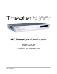
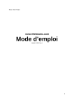
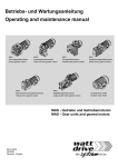
Image AnyPlace IA-200
User’s Manual
Version 1.01
User’s Manual 0020D1.01
Image AnyPlace IA-200
Copyright Information
Copyright © 2009 Flexible Picture Systems
All Rights Reserved.
The information contained in this document is protected by copyright. All rights are reserved by
Flexible Picture Systems.
Product names mentioned herein are used for identification purposes only and may be trademarks
of their respective companies.
Flexible Picture Systems and Image AnyPlace are trademarks or registered trademarks of Flexible
Picture Systems.
Page 2 of 49
© Flexible Picture Systems
Image AnyPlace
User’s Manual 0020D1.01
Contact Information
Address
Website
Technical Support
© Flexible Picture Systems
Flexible Picture Systems
174 West Beaver Creek Rd
Richmond Hill, ON L4B 1B4, Canada
Tel: 905-707-1664
Fax: 905-707-2304
http://flexiblepicturesystems.com/
E-mail: [email protected]
Page 3 of 49
User’s Manual 0020D1.01
Image AnyPlace IA-200
Revision History
Version
1.01
Page 4 of 49
Date
March 8, 2009
Description
Initial release.
© Flexible Picture Systems
Image AnyPlace
User’s Manual 0020D1.01
Table of Contents
Preface .........................................................................................................................................7
Limited Warranty ................................................................................................................................... 7
Return Material Authorization (RMA) ............................................................................................ 7
FCC Statement ....................................................................................................................................... 7
Safety 8
Disconnecting Instructions ................................................................................................................... 11
1 Introduction...........................................................................................................................12
1.1 General Description...................................................................................................................... 12
1.2 Product Variations and Nomenclature ......................................................................................... 14
1.3 Features and Specifications .......................................................................................................... 15
1.3.1 Video and Audio Signals .................................................................................................. 15
1.3.2 Video and Audio Processing Capability ........................................................................... 15
1.3.3 Controls............................................................................................................................. 16
1.3.4 Physical Characteristics .................................................................................................... 16
1.3.5 Panel Diagrams ................................................................................................................. 16
2 Installation and Operating Environment ............................................................................17
2.1 Setting up Your IA-200................................................................................................................ 17
2.2 Standby Mode .............................................................................................................................. 17
2.3 Software Operating Environment................................................................................................. 17
2.3.1 IA-200 Users (Keystone Correction Only) ....................................................................... 17
2.3.2 Router Manager ................................................................................................................ 17
2.3.3 IA-200 Control Tool ......................................................................................................... 18
2.3.4 eWarp Designer 200 ......................................................................................................... 18
2.3.5 Edge Blending Utility 200 ................................................................................................ 18
2.3.6 Updater.............................................................................................................................. 18
3 User Interface........................................................................................................................19
3.1 IR Remote Control ....................................................................................................................... 19
3.1.1 OSD Navigation Buttons .................................................................................................. 20
3.1.2 Video Source Selection Buttons ....................................................................................... 20
3.1.3 IA-200 Special Feature Selection Buttons........................................................................ 20
3.2 Operational Modes ....................................................................................................................... 20
4 On Screen Display................................................................................................................25
4.1 OSD Menu Structure.................................................................................................................... 25
5 Keystone and Geometry Correction ...................................................................................36
5.1 Operation of Keystone Control .................................................................................................... 36
5.2 User Warp Maps........................................................................................................................... 36
6 Aspect Ratio Treatment .......................................................................................................38
© Flexible Picture Systems
Page 5 of 49
User’s Manual 0020D1.01
Image AnyPlace IA-200
6.1 Aspect Ratio Treatments .............................................................................................................. 38
6.1.1 Supported Aspect Ratios................................................................................................... 38
6.1.2 Aspect Ratio Treatments Objectives................................................................................. 39
6.1.3 Input and Output Combinations........................................................................................ 40
7 Input Modes Supported .......................................................................................................45
8 Latency Considerations.......................................................................................................47
8.1 Low Latency Mode Configuration............................................................................................... 47
9 Glossary ................................................................................................................................49
Page 6 of 49
© Flexible Picture Systems
Image AnyPlace
User’s Manual 0020D1.01
Preface
These sections provide information you must read before using the IA-200.
Limited Warranty
All Flexible Picture Systems products are designed and tested to the highest standards and backed
by a one year parts and labor warranty. Warranties are effective upon the first delivery date to the
customer and are non-transferable.
Warranty related repairs include parts and labor, but do not include repair of faults resulting from
user negligence, special modifications, abuse (mechanical damage), shipping damage, and/or
other unusual damages.
The customer shall pay shipping charges when the unit is returned for repair. Flexible Picture
Systems will pay shipping charges for return shipments to customers.
Flexible Picture Systems does not assume responsibility for consequential damages, expenses or
loss of revenue, inconvenience or interruption in operation experienced by the customer.
Warranty service shall not automatically extend the warranty period.
No other warranty, expressed or implied, shall apply.
Return Material Authorization (RMA)
In the event that a product needs to be returned for repair, call Flexible Picture Systems at 905707-1664 and ask for an Applications Engineer to issue a Return Material Authorization number,
or send an e-mail to [email protected].
RMA Conditions
Refer to these conditions when returning a product:
•
•
•
•
Prior to returning any item, you must receive a Return Material Authorization (RMA)
number.
All RMA numbers must appear on the return-shipping label.
All RMA numbers are valid for ten (10) days from the issue date.
All shipping and insurance charges in all RMAs must be prepaid by the customer.
FCC Statement
This equipment has been tested and found to comply with the limits for Class B digital devices,
pursuant to Part 15 of the FCC Rules. These limits are designed to provide reasonable protection
© Flexible Picture Systems
Page 7 of 49
User’s Manual 0020D1.01
Image AnyPlace IA-200
against harmful interference in a residential/office installation. The equipment generates and can
radiate radio frequency energy and, if not installed and used in accordance with the instructions,
may cause harmful interference to radio communications. However, there is no guarantee that
interference will not occur in a particular installation. If this equipment does cause harmful
interference to radio or television reception, which can be determined by turning the equipment
off and on, the user is encouraged to try to correct the interference by one or more of the
following measures:
•
•
•
•
•
Reorient or relocate the receiving antenna.
Increase the separation between the equipment and receiver.
Connect the equipment into an outlet on a circuit different from that to which the receiver is
connected.
Consult the dealer or an experienced Radio/TV technician for help.
Changes or modifications not expressly approved by the party responsible for compliance
could void the user's authority to operate the equipment.
Safety
Take note of all the safety instructions presented in this section before using the IA-200.
Warnings and Warning Symbols
The Lightning Flash with arrowhead symbol within an equilateral
triangle is intended to alert the user to the presence of un-insulated
"dangerous voltage" within the product enclosure, voltage that may be of
sufficient magnitude to constitute a risk of shock to persons.
The exclamation point within an equilateral triangle is intended to alert
the user to the presence of important operating and maintenance
(servicing) instructions in the literature accompanying the product.
Warning! To reduce the risk of fire or electric shock, do not expose this apparatus to rain
or moisture and objects filled with liquids, such as vases, should not be placed on this
apparatus.
Warning! This apparatus is intended to be connected to a power outlet that includes a
protective earthing connection (i.e. a third pin ground). do not remove the third pin of the
power cable or connect the unit in any way that does not connect this pin to ground.
Page 8 of 49
© Flexible Picture Systems
Image AnyPlace
User’s Manual 0020D1.01
Important Safety Label Information
A label indicating important safety information is located on the bottom surface of the IA-200.
Important Safety Instructions
General
•
•
•
•
Read these instructions.
Keep these instructions.
Take note of all warnings.
Follow all instructions.
Installation
•
•
•
•
•
•
•
•
Do not use this apparatus near water.
Do not block any ventilation openings. Install in accordance with the manufacturer's
instructions.
Do not install near any heat sources such as radiators, heat registers, stoves, or other
apparatus (including amplifiers) that produce heat.
Do not defeat the safety purpose of the polarized or grounding-type plug.
A polarized plug has two blades with one wider than the other. A grounding type plug has
two blades and a third grounding prong. The wide blade and the third prong are provided for
your safety. If the provided plug does not fit into your outlet, consult an electrician for
replacement of the obsolete outlet.
Protect the power cord from being walked on or pinched, particularly at plugs, convenience
receptacles, and the point where they exit from the apparatus.
Only use attachments/accessories specified by the manufacturer.
Use only with the cart, stand, tripod, bracket, or table specified by the manufacturer, or sold
with the apparatus. When a cart is used, use caution when moving the cart/apparatus
combination to avoid injury from tip-over.
Operation
•
•
•
•
Clean only with dry cloth.
Unplug this apparatus during lightning storms or when unused for long periods of time.
Refer all servicing to qualified service personnel.
Servicing is required when the apparatus has been damaged in any way, such as powersupply cord or plug is damaged; liquid has been spilled or objects have fallen into the
apparatus; the apparatus has been exposed to rain or moisture, does not operate normally, or
has been dropped.
Installation
Attachments
Do not use attachments not recommended by the manufacturer, as they may result in the risk of
fire, electric shock, or injury to persons.
Water and Moisture
© Flexible Picture Systems
Page 9 of 49
User’s Manual 0020D1.01
Image AnyPlace IA-200
Do not use this unit near water; for example, near a bathtub, washbasin, kitchen sink or laundry
tub, in a wet basement, or near a swimming pool, water spa, or the like.
Heat
Do not use this unit near sources of heat, including heating vents, stoves, or other appliances that
generate heat. Also, do not place this product in temperature environments greater than 45ºC
(104ºF).
Mounting Surface
If not installing the unit in a standard equipment rack using the recommended mounting brackets,
place the unit on a flat, even surface. Do not place the unit on an unstable cart, stand, tripod,
bracket, or table. The unit may fall causing serious injury to a person and/or serious damage to
the appliance.
Portable Cart
An appliance and cart combination should be moved with extreme care. Quick stops, excessive
force, and uneven surfaces may cause the appliance and cart combination to overturn.
Ventilation
Locate the unit with adequate space around it so that proper heat ventilation is assured. Allow 10
cm (4 in) clearance from the rear and top of the unit, and 5 cm (2 in) from each side.
Slots and Openings
Slots and openings in the unit's case are provided for ventilation to ensure reliable operation of
the unit and to prevent overheating. These openings must not be blocked or covered. The
openings should never be blocked by operating the unit while placed on a bed, sofa, rug, or
similar surface. This unit should not be placed in a built-in installation such as a bookcase unless
adequate ventilation is provided.
Entry of Foreign Objects and Liquids
Never push foreign objects of any kind into this unit through the ventilation slots as they may
touch dangerous voltage points or short-circuit electrical/electronic parts that could result in fire,
or electric shock, or both. Never spill liquid of any kind onto the unit.
Electric Power
Only operate the unit from the type of electric power source indicated on the unit's labeling. If
you are not sure of the type of power supply that is available in your home or workplace, consult
your appliance supplier or local power company.
Grounding or Polarization
This unit is provided with a 3-pin, grounded, alternating current line plug. This plug will fit into
the power outlet only one way. This is a safety feature. Do not try to defeat the safety purpose of
the plug.
Power Cord Protection
Page 10 of 49
© Flexible Picture Systems
Image AnyPlace
User’s Manual 0020D1.01
Route power supply cords so that they are not likely to be walked on or pinched by placing items
upon or against them, paying particular attention to cords at plugs, convenience receptacles, and
the point where they exit from the product.
Overloading
Do not overload wall power outlets, extension cords, or integral convenience receptacles as this
can result in a risk of fire or electric shock.
Lightning
For added protection for this unit during a lightning storm, or when it is left unattended and
unused for long periods of time, unplug it from the power outlet. This will prevent damage to the
unit due to lightning or power surges.
Maintenance
Cleaning
Unplug this unit from the wall outlet before cleaning. Do not use liquid cleaners or aerosol
cleaners. Only use a soft cloth dampened with a mild detergent solution. Do not use strong
solvents such as alcohol, benzene, or paint thinner.
Damage Requiring Service
Unplug this unit from the power outlet and refer servicing to qualified service personnel under the
following conditions:
•
•
•
•
•
•
When the power cord or plug is damaged.
If liquid has been spilled or foreign objects have fallen into the unit.
If the unit has been exposed to rain or water.
If the unit does not operate normally, following the operating instructions. Adjust only those
controls that are covered by the operating instructions as improper adjustment of other
controls may result in damage and may require extensive work by a qualified technician to
restore the unit to normal operation.
If the unit has been dropped or the case has been damaged.
When the unit exhibits a distinct change in performance—this indicates a need for service.
Warning! Do not attempt to service this unit yourself as opening or removing covers
may expose you to dangerous voltage or other hazards. Refer all servicing to qualified
service personnel.
Disconnecting Instructions
In the event that power needs to be quickly disconnected from the IA-200 Processor, the user may
separate the power cable from the processor at the power entry module by firmly grasping the
power cable and pulling until the cable comes free.
© Flexible Picture Systems
Page 11 of 49
User’s Manual 0020D1.01
Image AnyPlace IA-200
1 Introduction
1.1
General Description
The Image AnyPlace IA-200 is a high performance video signal processor intended for use in Pro
AV applications. In addition to top ranked scaler features, the IA-200 adds Keystone Correction
capability (i. e. the ability to correct for the distortion caused by projecting off-axis onto a flat
screen). Variations on the IA-200 design add Image Geometry Correction (ability to correct for
projection onto a curved or irregular screen) and Edge Blending (the ability to invisibly blend
the overlapping output of 2 projectors) to the product. All IA-200 processors can be updated in
the field to add Image Geometry Correction and/or Edge Blending. Choosing the SDI option
(available at slight extra cost at the time of purchase) enables the user to add HD-SDI (and SDI)
input capability.
As a Scaler, the IA-200 offers the top quality image scaling provided by the Silicon Optix Realta
IC. All popular resolutions are supported on both input and output. In addition, the IA-200
functions as a switcher, supporting several different signal input types (see section 1.3.1).
As a Keystone Corrector, the IA-200 enables precision Keystone Correction for projection onto
any flat screen. All flat screen Keystone adjustments may be made with just 4 corner controls
internally available from the OSD (i. e. the user adjusts each corner of the projected image to
match the desired projection area in real time). In addition to off axis distortion, this approach
also simultaneously corrects for Screen/Projector Rotation, Screen Slant, and incorrect Screen
Aspect Ratio. The IA-200’s sub-pixel precision makes it an ideal choice of multiple projector
applications such as Projector Stacking for added brightness, and 2 projector 3D applications.
As a Geometry Correcter, the IA-200_EX extends precision Geometry Correction to image
shaping onto curved, spherical and even irregular screens. The IA-200_EX accomplishes this
sophisticated Geometry Correction using the eWarp Designer 200 PC based program. eWarp
Designer 200 enables the user to precisely shape the screen using a flexible grid 1 .
As an Edge Blender, IA-200_BEX adds Edge Blending to Keystone Correction and Geometry
Correction. Any number of projectors’ output may be blended on any type of surface. Edge
Blending is controlled by the Edge Blending 200 PC based program.
1
For Image AnyPlace IA-100 users: IA-100 grid files larger than 7x9 are compatible with IA-200; use the internal 4
point method of IA-200’s for 4 point Keystone Correction.
Page 12 of 49
© Flexible Picture Systems
Image AnyPlace
User’s Manual 0020D1.01
Figure 1: IA-200 Video Processor
In addition to its professional grade Scaler features and its unique Keystone Correction and
Geometry Correction and Edge Blending, the IA-200 adds HQV technology video processing
features to all video signals. Initially conceived in the military research labs of Lockheed Martin
and then refined and commercialized by Teranex and Silicon Optix, HQV video processing has
been the technology of choice of film and video professionals in broadcast and studio
environments for years. HQV signal processing includes the following powerful features:
•
•
•
•
•
•
•
State-of-the-art, motion-adaptive de-interlacing for both SDTV and HDTV
Temporal Recursive Noise Reduction
Codec Noise Reduction (includes mosquito noise reduction and block artifact removal)
Detail Enhancement
Fully-automatic detection and correction for multiple film/video cadences (3:2, 2:2, varispeed, 6:4, 8:7, etc.)
Brightness-Contrast Enhancement
Color Space Conversion and Color Temperature Adjustment
For more information on HQV technology, visit http://www.hqv.com.
© Flexible Picture Systems
Page 13 of 49
User’s Manual 0020D1.01
Image AnyPlace IA-200
Figure 2: Typical IA-200 Application
IA-200 is controlled through a simple 20-button IR remote control unit (see Figure 5). Simple
navigation keys bring access to a simple, yet elegant OSD (On Screen Display). Video input
device selection is accomplished using dedicated IR remote buttons. Access to the HQV features
is also provided through dedicated IR remote buttons.
IA-200 provides the professional user with flexible control methodologies of RS-232, USB, and
Ethernet. For details on the control programming protocol, refer to the IA-200 Programming
Manual.
IA-200 is implemented in a compact and attractive desktop package that can be rapidly fitted to a
standard 19" rack using a separately ordered rack mounting kit, part number IA-200_RM.
1.2
Product Variations and Nomenclature
The IA-200 product has several different variations, described below:
IA-200
IA-200_EX
IA-200_BEX
Page 14 of 49
IA-200 scaler with Keystone Correction. Keystone Correction is
implemented internally. No PC software is required.
Adds Geometry Correction to the IA-200. Geometry Correction is
implemented with the eWarp Designer 200 software (which creates the
grid based Warp Maps, and downloads them to the IA-200 hardware).
eWarp Designer 200 access is enabled through a serial number based
key, which is permanently stored (in the manufacturing process or by
field upgrade) on the IA-200 hardware. If you have an IA-200 and you
would like to add Geometry Correction, you can purchase an
IA-200_eWARP_Key.
Adds Edge Blending capability to the IA-200_EX. Blending is
implemented with the Edge Blending Utility 200 software (which creates
© Flexible Picture Systems
Image AnyPlace
User’s Manual 0020D1.01
IA-200_XXX_SDI
1.3
the blend regions, and downloads them to the IA-200 hardware). Edge
Blending Utility 200 access is enabled through a serial number based
key, which is permanently stored (in the manufacturing process or by
field upgrade) on the IA-200 hardware. If you have an IA-200 or IA200_EX and you would like to add Edge Blending, you can purchase an
IA-200_EB_Key. The Edge Blending Key is different than the eWarp
Key. The IA-200_BEX product definition includes both Keys.
Any of the IA-200 options can be ordered with or without SDI (actually
HD-SDI, but accepts SDI as well). Since the SDI option involves
hardware (i.e. connectors and components that are loaded or not at the
time of manufacture), no field upgrade is possible.
Features and Specifications
1.3.1 Video and Audio Signals
Table 1: Video and Audio Signals (see section 5 for resolution range)
Signal Type
Input
Output
Video
• Composite Video (NTSC, PAL, and
SECAM)
• S-Video (NTSC and PAL)
• Component (YPbPr for SDTV and HDTV in
American and European formats)
• Analog RGB (VGA to SXGA60Hz)
• DVI (VGA to QXGA)
• HDMI
• SDI (including HD-SDI and audio) (included
with SDI option only)
• S/PDIF
• Toslink
• HDMI
• Analog RGB (VGA to
UXGA)
• DVI (VGA to QXGA)
• HDMI
Audio
• S/PDIF
• Toslink
• HDMI
1.3.2 Video and Audio Processing Capability
These are the video and audio features supported:
•
•
•
•
•
•
•
•
Scaling
Extreme Keystone Correction (+/- 40º horizontal, +/- 30º vertical)
Geometry Correction for projection on curved or irregular surfaces (with EX versions)
Edge Blending for blending multiple projectors’ output (BEX versions)
Audio Delay
Input Switching
Aspect Ratio Correction
HQV Video Processing
© Flexible Picture Systems
Page 15 of 49
User’s Manual 0020D1.01
o
o
o
o
•
Image AnyPlace IA-200
Temporal-Recursive Noise Reduction
Codec Noise Reduction
Fully-automatic cadence detection and correction
Detail Enhancement
Advanced motion-adaptive de-interlacing
1.3.3 Controls
IA-200 may be remotely controlled over 3 different interfaces, as well as the user operated IR
Remote. IA-200 may be controlled by any of IA-200’s application programs (eWARP Designer
200, IA-200 Control Tool, Updater and Router Manager) and for connection to Crestron/AMX
type systems:
•
•
•
RS-232
USB
Ethernet
1.3.4 Physical Characteristics
These are the physical characteristics of the IA-200:
Dimensions
Weigh
Power
17.0" x 9.7" x 1.75"(43.2 x 24.6 x 4.4 cm)
7 lbs. (3.2 kg)
100-240V, 47-63 Hz, 27W (typical)
1.3.5 Panel Diagrams
Figure 3: Front Panel Drawing
Figure 4: Rear Panel Drawing
Page 16 of 49
© Flexible Picture Systems
Image AnyPlace
User’s Manual 0020D1.01
2 Installation and Operating Environment
2.1
Setting up Your IA-200
The IA-200 Quick Start Guide is intended to provide a quick list of steps that you can follow to
get things working in 95% of installations. Please refer to the Quick Start Guide for basic
installation instructions. This section and the subsequent User Interface is intended for more
advanced installations, problem solving and the general background of the product.
2.2
Standby Mode
The IA-200’s power switch is located on the back of the system.
A momentary contact Standby/Operate button is located at the extreme left of the front panel
(and is also implemented as a red button on the IR Remote.)
Standby mode is a low power mode which suspends the IA-200’s output to the projector. During
Standby mode, the IA-200’s front panel display is active and Remote Control are active, but in a
different context. In addition to provide an Instant On IR response from its low power output
setting, the Standby state enables the user to adjust parameters that would generally not be
adjusted during normal OSD operation. One benefit of this operation is that the user cannot
make a casual OSD keystroke error that, for example, resets the display resolution to something
that the display cannot support (causing the screen to go blank and depriving the user of the
visual feedback that he needs to fix the problem).
2.3
Software Operating Environment
IA-200 comes with a CD with several different applications. Depending on your intended use,
you may require none, some or all of the applications. The Quick Start Guide describes how to
install the CD. This section briefly describes the software environment.
2.3.1 IA-200 Users (Keystone Correction Only)
No software is required (as long as you do not need to control anything over RS-232, USB or
Ethernet). All operation is achieved through the IR remote Control and OSD.
2.3.2 Router Manager
If you want to do anything else other than basic scaling and Keystone Correction, you need to run
Router Manager and install your specific IA-200. Router Manager is the common
© Flexible Picture Systems
Page 17 of 49
User’s Manual 0020D1.01
Image AnyPlace IA-200
communications and control layer that enables each IA-200 application to quickly identify that a
specific IA-200 is attached and ready to communicate. Basic details on how to quickly connect
are provided in the Quick Start Guide. In depth explanation is provided in the Router Manager
Manual.
2.3.3 IA-200 Control Tool
IA-200 Control is intended as Control Program Emulator and Control Script Development tool.
Use the IA-200 Control Tool to experiment with IA-200 Control Protocol, and develop scripts of
ASCII based protocol (described in the IA-200 Programmer’s Guide). These scripts can then be
imported into popular Pro AV controllers such as Crestron and AMX for control of the IA-200 in
a large installation. The IA-200 Control Utility does not require a software key for operation.
Installation with Router Manager is not required for IA-200 Control Tool.
2.3.4 eWarp Designer 200
eWarp Designer 200 is used to develop grid based Geometry Correction for the IA-200_EX and
IA-200_BEX versions. eWarp Designer 200 requires a serial number based Key for operation.
The key is installed during manufacturing or may be installed in the field (key installation is
accomplished with eWarp Designer 200 itself). Correct installation with Router Manager is
required for eWarp Designer 200operation.
2.3.5 Edge Blending Utility 200
Edge Blending Utility 200 is used to control Edge Blending in IA-200_BEX versions. Edge
Blending Utility 200 requires a serial number based Key for operation. The key is installed
during manufacturing or may be installed in the field (key installation is accomplished with Edge
Blending Utility 200 itself). Correct installation with Router Manager is required for Edge
Blending Utility 200 operation.
2.3.6 Updater
Update is used to provide firmware updates to all versions of IA-200. Updater connects directly
to the IA-200 in Service Mode. Please see the Updater manual for details on Service Mode and
the use of Updater. Updater does not require Router Manager.
Page 18 of 49
© Flexible Picture Systems
Image AnyPlace
User’s Manual 0020D1.01
3 User Interface
3.1
IR Remote Control
All IA-200 user interface controls are accessed via infrared (IR) remote control. The remote has
following groups of controls:
•
•
•
OSD Navigation (including the On/Setup Key)
Video Source Selection
IA-200 Special Feature Selection
You may also select video sources and HQV processing features through the OSD navigation
controls; however, dedicated IR remote keys provide you with quick one-touch access to the most
frequently used commands. Figure 5 illustrates the IA-200 remote control.
Figure 5: Remote Control
© Flexible Picture Systems
Page 19 of 49
User’s Manual 0020D1.01
Image AnyPlace IA-200
3.1.1 OSD Navigation Buttons
These are the OSD navigation buttons on the IR remote.
•
•
•
•
The On/Setup (indicated as Power) button toggles the IA-200 between On and Setup modes
of operation (as described in Operational Modes).
The Menu button is used to invoke the OSD main menu.
The Up/Down/Left/Right arrow buttons are used to navigate the OSD.
The Enter/Select button is used to activate an OSD menu selection.
3.1.2 Video Source Selection Buttons
Direct (one-touch) input selection is possible using the following buttons:
•
•
•
•
•
•
•
The RGB button selects the VGA port as the active input.
The DVI button selects the DVI port as the active input.
The Video button selects the composite video port as the active input.
The S-Video button selects the S-Video port as the active input.
The YPbPr button selects component video as the active input.
The HDMI button selects HDMI as the active input.
The SDI button selects the SDI port as the active input
3.1.3 IA-200 Special Feature Selection Buttons
Additional buttons are available to directly access key video processing features and to cycle
through the available enhancements:
•
•
•
•
•
•
3.2
The LUT button cycles through pre-loaded, and user programmed input LUT (Look Up
Tables, which can be used to brighten or darken the appearance of incoming video
The TRNR button accesses the Temporal Recursive Noise Reduction feature, cycling
through the four available settings (Off, Low, Medium, and High).
The CNR button accesses the Codec Noise Reduction feature, cycling through the four
available settings (Off, Low, Medium, and High).
The eWarp button cycles through the available User defined Warp Maps (created by eWarp
Generator and stored in Index 1 through Index 8)
The Split button activates/deactivates a split-screen mode for direct comparison of the image
with and without noise reduction activated.
The Test cycles through a series of embedded Test Patterns which are instantly rendered at
the current output resolution
Operational Modes
The IA-200 has two operational modes, On and Setup (Stand-by). These modes are selected by
a dedicated key on the IR remote. The IA-200 also enables selection using the On Mode using
the ASCII control protocol with RS-232, USB, or Ethernet.
Page 20 of 49
© Flexible Picture Systems
Image AnyPlace
User’s Manual 0020D1.01
3.2.1.1 On Mode
On Mode is entered by toggling the On/Setup button on the IR remote. A brief transition of
about 3 seconds occurs when On Mode is entered. During this transition period, the 24 x 2 LCD
Display indicates
IA-200
Please Wait
In On Mode, the video output signals are activated and you may control all of IA-200 parameters
with the remote control (except for Setup restricted parameters, as noted below). The LCD front
panel display indicates the following information in its 24 x 2 character matrix:
Input=Connector Resolution
Output=Resolution
Depending on which IR remote key that you select, the operation of the OSD is slightly different:
•
If you select the Menu key, the IA-200’s OSD appears on the screen.
The OSD remains on the screen until you press the Menu key once again or until 30 seconds
with no IR remote activity passes. Complete details on the OSD may be found in the On
Screen Display.
•
If you select one of the dedicated IA-200 Special Feature keys, the IA-200 special feature is
immediately activated.
A brief message indicating the status of the selected IA-200 special feature appears
momentarily on the screen (e.g. TRNR = Medium or CNR = Off).
•
If you select one of the Input Source keys, the selected source is chosen as the input.
The previously selected IA-200 Special Features, Scaling and Video Parameters are all
preserved for each input; each input appears exactly as you left it.
The IA-200 powers up in On Mode. All operational parameters are retained from the previous
session. A Factory Reset returns all parameters to the default state (defaults are described in the
On Screen Display), except for the input signal. The input signal most recently used is retained as
the power-up input signal.
3.2.1.2 Setup (Stand-by) Mode
Setup mode is entered by toggling the On/Setup button on the IR remote.
In Setup mode, the IA-200 is in a low-power state. The output signals are de-activated (no output
will appear on your display device). Setup mode enables you to power the unit down, but still
leaves the IR receiver circuitry energized so that you can re-start the system with the IR remote.
When the unit is in Setup Mode, you can also make adjustments to certain sensitive parameters,
such as Output Resolution. Visual feedback for the adjustments of Setup Mode is seen on the 24
x 2 LCD display, rather than on OSD of the main screen. Sensitive parameters are placed in the
Setup Menu so that an inadvertent key stroke with the IR remote does not cause a change in a
parameter from which that would be difficult to recover.
Table 2 lists the Setup parameters and Table 3 lists the output resolutions currently supported in
the unit.
© Flexible Picture Systems
Page 21 of 49
User’s Manual 0020D1.01
Image AnyPlace IA-200
Table 2: Setup Parameters
Parameter
Description*
OUT = XXX ## Hz
Cycles through all of the available IA-200 output modes
(see Table 3 for a list of Output Resolutions).
Turns On (Off) the 24 x 2 LCD Display during On Mode
LCD Brightness = On (Off)
BAUD = #####
PC Control = Active (Inactive)
Lets you choose a baud rate of 1200, 9600, 19200, 57600,
or 115000.
The OSD may be located pre (Input side) or post (Output
side) scaling and keystone correction
Turns On (Off) the computer control capability
DHCP = Enabled (Disabled)
Turns on Dynamic IP Address Selection
IP=aaa.bbb.ccc.ddd
Select IP Address (selectable only if DHCP = Disabled)
DNS=aaa.bbb.ccc.ddd
Select DNS Address (selectable only if DHCP = Disabled)
OSD Location = Input (Output)
nd
2 DNS=aaa.bbb.ccc.ddd
SubMask=aaa.bbb.ccc.ddd
Select Alternate DNS Address
(selectable only if DHCP = Disabled)
Select Gateway Address (selectable only if DHCP =
Disabled)
Select SubNet Mask (selectable only if DHCP = Disabled)
MAC = ## ## ## ## ## ##
Indicates the MAC Address of IA-200 unit
Serial No = ######
Indicates the Serial # of IA-200 unit
µProc Rev = #.##
Indicates the Rev # of the Front Panel microprocessor.
Gateway=aaa.bbb.ccc.ddd
* The default parameters configurations are highlighted in bold.
Table 3: Output Modes
Output Mode
Comments
VGA 60 Hz (640 x 480)
VGA 50 Hz (640 x 480)
848 x 480 60 Hz
SVGA 60 Hz (800 x 600)
SVGA 50 Hz (800 x 600)
720p 60 Hz (1280 x 720)
720p 50 Hz (1280 x 720)
XGA 60 Hz (1024 x 768)
XGA 72 Hz (1024 x 768)
XGA 50 Hz (1024 x 768)
1360 x 768 60 Hz
1365 x 768 60 Hz
1400 x 788 60 Hz
SXGA 60 Hz (1280 x 1024)
VESA Standard
VESA Standard
Panel timing
VESA Standard
VESA Standard
SMPTE Standard
SMPTE Standard
VESA Standard
VESA Standard
VESA Standard
NEC timing
NEC timing
Panel timing
VESA Standard
Page 22 of 49
© Flexible Picture Systems
Image AnyPlace
User’s Manual 0020D1.01
Output Mode
Comments
SXGA 50 Hz (1280 x 1024)
SXGA+ 60 Hz (1400 x 1050)
SXGA+ 50 Hz (1400 x 1050)
1080p 60 Hz (1920 x 1080)
1080p 50 Hz (1920 x 1080)
1080p 48 Hz (1920 x 1080)
QXGA 60 Hz (2048 x 1536)
QXGA 50 Hz (2048 x 1536)
QXGA 48 Hz (2048 x 1536)
UXGA 60Hz (1600 x 1200)
1365 x 1024 50 Hz
1365 x 1024 60 Hz
1360 x 1024 60 Hz
1280 x 768 60 Hz
Digital Cinema 60 Hz (2048 x
1080)
Digital Cinema 24 Hz (2048 x
1080)
WUXGA 60 Hz (1920 x 1200)
1366 x 768
Reserved 9
Reserved 10
Reserved 11
Reserved 12
VESA Standard
VESA Standard
VESA Standard
SMPTE Standard
SMPTE Standard
SMPTE Standard
VESA Standard
JVC timing
JVC timing
JVC timing
VESA Standard
VESA Standard
Panasonic Timing
Reserved for future use
Reserved for future use
Reserved for future use
Reserved for future use
3.2.1.3 Setting Up the Unit
On entry to the Setup mode, the 24 x 2 LCD display indicates the following:
IA-200
Setup
Select the Menu key on your IR remote to bring up the Setup Menu on the 24 x 2 LCD display.
The LCD display indicates the following:
Parameter = Value
Setup Mode
Using the up/down navigation keys on the remote, you can select the next parameter in a circular
list of parameters. Using the left/right navigation keys on the remote, you can select the value of
the parameter. In some cases, the parameter is visible in the setup menu, but may not be altered
(such as Serial Number or MAC Address).
Selection of IP addresses is slightly different. IP addresses may only be selected if the DHCP
parameter has been set to "Off". In this case, you use the left/right navigation key to "enter" the
© Flexible Picture Systems
Page 23 of 49
User’s Manual 0020D1.01
Image AnyPlace IA-200
IP address. The left key will highlight the rightmost octet; the right key will select the leftmost
octet. The up/down keys may then be used to increase/decrease the value of the octet.
Subsequent presses of the left/right key highlight the octet immediately to the left/right. The
up/down keys may then be used to increase/decrease the value of the octet. When the
leftmost/rightmost octet is selected, an additional left/right key selection "exits" the IP address.
The up/down arrows may then be used to select the next parameter. Table 2 lists the Setup
parameters.
Page 24 of 49
© Flexible Picture Systems
Image AnyPlace
User’s Manual 0020D1.01
4 On Screen Display
4.1
OSD Menu Structure
The OSD is the primary way of controlling and selecting functions in the IA-200 system. When
first powered up, the IA-200 is in a Factory Default configuration, with English as the OSD
language, Component Video as Video Input, and S/PDIF Audio as Audio input. All other Factory
Default parameters are indicated in Table 5.
When you select the Factory Reset from the OSD menu, IA-200 reloads all of these default
parameters, replacing any adjustments previously made. As indicated in the User Interface, the
Setup Parameters are not affected by Factory Reset.
IA-200 preserves all the signal processing parameters on a selected input basis. When you power
down or select a different input, the processing parameters previously selected are automatically
re-established when returning to that input. An Input Reset sets the currently selected input to its
default parameters. (This allows you to reset a specific input channel without disturbing
selections that affect the entire IA-200 operation).
A complete view of the OSD menu structure is shown in Table 4 and Table 5.
Table 4: OSD Main Menu Structure
Icon On
Icon Off
Description
Functionality
Inputs
Enter this submenu to select the video or audio input.
Picture
Enter this menu to adjust the image brightness, contrast,
sharpness, gamma correction, black level, color
temperature, color, hue, tint, and aspect ratio.
Setup
Enter this submenu to review the video system, select the
background color, reset to default settings, and setup the
menu position.
Enter this submenu to select the language used by the OSD.
Language
© Flexible Picture Systems
Page 25 of 49
User’s Manual 0020D1.01
Icon On
Image AnyPlace IA-200
Icon Off
Description
Functionality
Info
Enter this submenu to view information about the system
(input resolution, horizontal and vertical frequency, output
resolution, horizontal and vertical frequency, firmware
revision, FPGA revision, serial number, and IP address).
Advanced
Enter this submenu to access the advanced menu options.
Table 5: OSD Complete Menu Structure
OSD Menu Level
Level 1
Level 2
Video
Inputs
Audio
Audio Delay
Picture
Page 26 of 49
Level 3
Comments
Level 4
Level 5
Component
-
-
HDTV or SDTV
VGA
-
-
SDTV, HDTV, or Graphics
DVI
-
-
Graphics, RGB HDTV
S-Video
-
-
SDTV
Composite
-
-
SDTV
SDI
-
-
SDI input selection
HDMI
-
-
HDMI input selection
TosLink
-
-
S/PDIF
Selects TosLink as audio source
Selects S/PDIF as audio source
HDMI
Selects HDMI as audio source
SDI
-
-
-100 - +100, 0
(default)
-
-
Brightness
0 - 100,
50 (default)
Contrast
0 - 100,
50 (default)
Selects SDI as audio source
Adjusts the Audio Delay through
IA-200. The Audio Delay is
calibrated in milliseconds. A delay
of ‘0’ selects a delay that is
automatically adjusted to the
number of frames of delay
introduced by IA-200 processing.
The Audio Delay adjustment allows
the user to compensate for Audio
or Video delay that is introduced by
other system components
-
The higher the setting, the greater
the brightness.
The lower the setting, the lower the
brightness.
-
The higher the setting, the greater
the contrast.
The lower the setting, the lower the
contrast.
Picture
Settings
© Flexible Picture Systems
Image AnyPlace
User’s Manual 0020D1.01
OSD Menu Level
Level 1
Level 2
Level 3
Comments
Level 4
Level 5
Gamma 1.0
(default)
The higher the setting, the
sharper the image (edge
enhancement).
The lower the setting, the lower
the sharpness.
The higher the setting, the
better the image (detail
enhancement).
The lower the setting, the lower
the detail enhancement.
Gamma LUT for linear
processing response.
Gamma 1.5
Gamma LUT
Sharpness
0 - 100,
50 (default)
-
Detail
Enhancement
0 - 100,
0 (default)
-
Gamma 2.2
Input
Gamma
Gamma 2.4
Gamma 2.5
Picture
Picture
Settings
Gamma 2.8
Gamma
Mode
Gamma 1.0
(default)
Gamma 2.2
Output
Gamma
Gamma 2.4
Gamma 2.5
Gamma 2.8
Color Temp
Color
© Flexible Picture Systems
9300K
-
6500K
(default)
-
5500K
-
0 - 100,
50 (default)
-
Gamma LUT
Gamma LUT
Gamma LUT
Gamma LUT
Gamma LUT for linear
processing response.
Gamma LUT
Gamma LUT
Gamma LUT
Gamma LUT
Gives a blue tint to the white
colors.
Gives a neutral tint to the white
colors.
Gives a red tint to the white
colors.
The higher the setting, the
greater the Color Saturation.
The lower the setting, the lower
the Color Saturation.
Page 27 of 49
User’s Manual 0020D1.01
Image AnyPlace IA-200
OSD Menu Level
Level 1
Level 2
Comments
Level 3
Level 4
Level 5
Hue
0 - 360,
180
(default)
-
Input Reset
Confirm
YES/NO
-
Standard
(default)
-
-
Full Screen
-
-
Picture
Settings
Picture
Aspect
Ratio
Page 28 of 49
The higher the setting, the
more greenish the picture. The
lower the setting, the more
purplish the picture.
Returns all of the adjustments
for a single input to the Factory
Default state. All the other
inputs and selections that affect
the IA-200 operation (such as
Keystone Correction) are
unaffected
Maintains the aspect ratio:
• 4:3 input and 16:9 output Output image would be
displayed with black pillar
bars (maintains input
aspect ratio)
• 4:3 input and 4:3 output No change
• 16:9 input and 16:9 output No change
• 16:9 input and 4:3 output Output image would be
displayed with black letter
box bars (maintains input
aspect ratio)
Fills the Output Screen by
stretching the image (distorting
the aspect ratio):
• 4:3 input and 4:3 output –
Grayed out, no action
• 4:3 input and 16:9 output –
Image is linearly stretched
horizontally to fill the output
screen
• 16:9 input and 4:3 output Image is linearly stretched
vertically to fill the output
screen
• 16:9 input and 16:9 output
– Grayed out, no action
See Aspect Ratio Treatments
for more information.
© Flexible Picture Systems
Image AnyPlace
User’s Manual 0020D1.01
OSD Menu Level
Level 1
Picture
Level 2
Aspect
Ratio
© Flexible Picture Systems
Level 3
Comments
Level 4
Level 5
Crop
-
-
Anamorphic
-
-
Flexview
-
-
Fills the Output Screen by
cropping the image
(maintaining aspect ratio).
• 4:3 input and 4:3 output –
Grayed out, no action
• 4:3 input and 16:9 output –
Top and bottom portions of
the image are cropped
• 16:9 input and 4:3 output –
Left and right portions of
the image are cropped
• 16:9 input and 16:9 output
– Grayed out, no action
See Aspect Ratio Treatments
for more information.
This mode is used with DVDs
(Standard Definition) that are in
Widescreen [16:9] format:
• 4:3 input and 4:3 output –
The image is letter boxed
• 4:3 input and 16:9 output –
The image appears full
screen
• 16:9 input and 4:3 output –
Grayed out, no action
• 16:9 input and 16:9 output
– Grayed out, no action
See Aspect Ratio Treatments
for more information.
Fills the Output Screen by
stretching the image (distorting
the aspect ratio):
• 4:3 input and 4:3 output –
Grayed out, no action
• 4:3 input and 16:9 output –
Image is non-linearly
stretched horizontally to fill
the output screen
• 16:9 input and 4:3 output –
Grayed out, no action
• 16:9 input and 16:9 output
– Grayed out, no action
See Aspect Ratio Treatment for
more information.
Page 29 of 49
User’s Manual 0020D1.01
Image AnyPlace IA-200
OSD Menu Level
Level 1
Level 2
Level 3
Squeeze
Comments
Level 4
-
Level 5
-
Squeezes 16:9 pre-stretched
inputs to 4:3 presentation
• 4:3 input and 4:3 output –
grayed out, no action
• 4:3 input and 16:9 output –
grayed out, no action
• 16:9 input and 4:3 output –
full screen 16:9 input is
squeezed to full screen 4:3
(this aspect ratio treatment
assumes 16:9 input that
has been horizontally prestretched from a 4:3
source)
• 16:9 input and 16:9 output
– full screen 16:9 input is
squeezed to 4:3 and
presented in a pillar box
•
Aspect
Ratio
Picture
Theater
Scope
Picture
Position
Page 30 of 49
Vertical
-
0 - 100
(this aspect ratio
treatment assumes 16:9
input that has been
horizontally prestretched from a 4:3
source
-
Provides aspect ratio
treatments for a system that
includes an Anamorphic Lens.
• 4:3 input and 4:3 output –
the central 16:9 aspect
ratio strip is cropped and
scaled to full screen output.
• 4:3 input and 16:9 output the central 2.35 aspect
ratio strip is cropped, and
scaled to full screen output.
• 16:9 input and 4:3 output –
full screen 16:9 input is
squeezed to full screen
output
• 16:9 input and 16:9 output
– the central 2.35 aspect
ratio strip is cropped, and
scaled to full screen output.
-
Adjusts the vertical position of
image (default setting depends
on the input video/graphics
source)
© Flexible Picture Systems
Image AnyPlace
User’s Manual 0020D1.01
OSD Menu Level
Level 1
Level 2
Level 3
Level 4
Level 5
Picture
Position
Horizontal
0 - 400
-
Autosync
-
-
-
Clock
Sync
Phase
Picture
Overscan
Right
Overscan
Top
Bottom
Menu
Position
© Flexible Picture Systems
0 - 200,
100
(default)
0 - 100,
50 (default)
Adjusts the horizontal position
of image (default setting
depends on the input
video/graphics source)
Automatically centers the
image for graphic inputs
-
Adjusts clock sync
-
Adjusts clock phase
Off
-
-
On
-
-
Status
Left
Setup
Comments
0.0 – 10.0
0.0 (default)
0.0 – 10.0
0.0 (default)
0.0 – 10.0
0.0 (default)
0.0 – 10.0
0.0 (default)
-
Center
-
-
Top Left
-
-
Top Right
-
-
Bottom Left
-
-
Bottom Right
-
-
Sets the percentage of
Overscan on the left edge
Sets the percentage of
Overscan on the right edge
Sets the percentage of
Overscan on the top edge
Sets the percentage of
Overscan on the bottom edge
Sets the OSD menu position in
the center of the display
Sets the OSD menu position in
the top left corner of the display
Sets the OSD menu position in
the top right corner of the
display
Sets the OSD menu position in
the bottom left corner of the
display
Sets the OSD menu position in
the bottom right corner of the
display
Page 31 of 49
User’s Manual 0020D1.01
Image AnyPlace IA-200
OSD Menu Level
Level 1
Level 2
Test
Patterns
Level 3
-
Comments
Level 4
Level 5
-
-
Off (default)
-
On
-
Off (default)
-
On
-
Setup
Trigger A
12 V
Triggers
Trigger B
Language
Info
Page 32 of 49
Factory
Reset
Confirm
YES/NO
-
-
English
-
-
-
French
German
Italian
Spanish
Portuguese
Swedish
Russian
Japanese
-
-
-
Chinese
Simplified
-
-
-
Chinese
Traditional
-
-
-
Korean
-
-
-
Input
Resolution
-
-
-
Displays test pattern images on
screen, with OSD off. Up- and
down-arrows navigate user
through all 10 available test
patterns. Left-arrow key returns
user to Test Pattern menu. Test
patterns:
• Screen boundary with circle
• 100 % Color bars
• Full White
• Full Black
• White Adjustment (levels
253, 254, 255)
• Black Adjustment (levels 0,
1, 2)
• Gray Bars
• Resolution alignment
• RGB Bars
• Grid
Sets Trigger A off.
Sets Trigger A on.
Sets Trigger B off.
Sets Trigger B on.
Resets to default settings
Selects the language for the
OSD menus
Shows the source resolution
© Flexible Picture Systems
Image AnyPlace
User’s Manual 0020D1.01
OSD Menu Level
Level 1
Info
Comments
Level 2
Level 3
Level 4
Level 5
Input H
Frequency
-
-
-
Shows the source H frequency
Input V
Frequency
-
-
-
Shows the source V frequency
Output
Mode
-
-
-
Shows the display mode
Output
Resolution
-
-
-
Shows the display resolution
Output H
Frequency
-
-
-
Shows the display H frequency
Output V
Frequency
-
-
-
Shows the display V frequency
Sync
-
-
-
Shows the synchronization type
Firmware
Revision
-
-
-
Shows the firmware revision
number
Serial
Number
-
-
-
Shows the board serial
number.
Shows the IP address only if
the Ethernet cable is connected
to the board and the IP address
has been assigned by DHCP
IP Address
FPGA
Revision
Standby
Micro
Rev. #
© Flexible Picture Systems
-
-
-
-
-
-
-
-
-
Shows the current revision
number for the FPGA code
Shows the firmware revision
number for the standby-mode
microcontroller
Page 33 of 49
User’s Manual 0020D1.01
Image AnyPlace IA-200
OSD Menu Level
Level 1
Level 2
Level 3
Comments
Level 4
Level 5
H
Top Left
V
Reset
H
Bottom Left
V
Reset
Projectio
n
Keystone
H
Top Right
V
Reset
H
Bottom Left
V
Reset
Advanced
Low
Latency
Reset
-
Off
-
-
On
-
-
Extra Low
-
-
Video
-
-
Cinema
-
-
Vivid
-
-
Dark Scene
-
-
Bright Scene
-
-
Graphics
-
-
BCE
Page 34 of 49
Top Left Corner H deviation
in + pixels
Top Left Corner V deviation in
+ pixels
Resets Top Left Corner
Bottom Left Corner H
deviation in + pixels
Bottom Left Corner V
deviation in - pixels
Resets Bottom Left Corner
Top Right Corner H deviation
in - pixels
Top Right Corner V deviation
in + pixels
Resets Top Right Corner
Bottom Right Corner H
deviation in - pixels
Bottom Right Corner V
deviation in - pixels
Resets Top Right Corner
Resets Entire Keystone
Projection
Low Latency Mode is Off;
HQV De-interlacing and
Noise Reduction is enabled
Low Latency Mode is On;
HQV De-Interlacing and
Noise Reduction is disabled
Extra Low Latency Mode is
On; HQV De-interlacing and
Noise Reduction is disabled;
VJam or VAdjust Sync Modes
are forced
Full range video is 16 - 235;
use for video sources
Film Enhancement for video
sources
High Color Saturation
Enhancement for video
sources
Dark Scene Enhancement for
video sources
Bright Scene Enhancement
for video sources
Full range video is 0 - 255;
use for computer graphics
sources
© Flexible Picture Systems
Image AnyPlace
User’s Manual 0020D1.01
OSD Menu Level
Level 1
Level 2
HQV
Processin
g
Level 3
Level 4
Level 5
HQV
Processing
Auto
-
TRNR
-
CNR
-
0-4
-
Off
Low
Mid
High
Off
Low
Mid
High
-
Split
-
-
Bottom
-
-
Left
-
-
Right
-
-
Top
-
-
Enable
-
-
Off
-
-
Index 1 - 8
-
-
Auto Bias
TRNR Level
CNR Level
Advanced
Edge
Blending
User Warp
Map
Selection
© Flexible Picture Systems
Comments
Automatically sets up Noise
Reduction according to Auto
Bias
Enables specific adjustment
of Temporal Recursive Noise
Reduction
Enables specific adjustment
of Codec Noise Reduction
Selects amount of HQV
processing 0 - 4
No adjustment
Adjusts TRNR
Adjusts TRNR
Adjusts TRNR
No adjustment
Adjusts CNR
Adjusts CNR
Adjusts CNR
Enables/Disables Screen
Split
Enable Edge Blending on
Bottom Edge
Enable Edge Blending on Left
Edge
Enable Edge Blending on
Right Edge
Enable Edge Blending on Top
Edge
Overall Enable/Disable on
Edge Blending
No Custom Warp Map
Selection (Keystone is
enabled)
Selects user warp map by
index
Page 35 of 49
User’s Manual 0020D1.01
Image AnyPlace IA-200
5 Keystone and Geometry Correction
5.1
Operation of Keystone Control
Keystone Control is activated by selecting the Keystone sub-menu from the Projection sub-menu
in the Advanced main menu. Keystone Control operates significantly differently from the IA-100
predecessor product’s Keystone Control.
Keystone Control can only be operated from the OSD Menu and Control Protocol (i.e. there is no
4 point equivalent to the eWarp Designer program used with IA-100). To use Keystone Control,
take the following steps:
1. Ensure that the output resolution and aspect ratio of the IA-200 are the same as those of the
projector in use.
2. Select one of the IA-200’s source channels.
3. Play live content to the selected source channel (the best content is a complete white test
pattern; since the OSD of IA-200 is used to render the internal IA-200 test patterns, it is
unfortunately not possible to use the internal test patterns for this purpose) . Ensure that the
source content has sufficient contrast such that you can clearly see all of the corners of the
input.
4. Adjust the position of the display to match the screen’s corners using the Keystone controls.
5. The Keystone adjustment is adjustable in single pixel increments. Adjustments downwards
and to the left are taken as positive. Adjustments upwards and to the left are taken as
negative. Each control is active using only the Horizontal arrows (i.e. you cycle between H
and V adjustments using Up and Down Arrows only; you adjust the value of H and V
adjustments using the Left and Right Arrows only.
6. Each corner of the display is separately adjusted. The total amount of adjustment is
interdependent with other concurrent Keystone adjustments (i.e. on a 1080p output, you can
adjust the H range of a given corner to a maximum deviation, if there is no concurrently
selected V deviation. You can also adjust a corner’s V deviation to 350 pixels if there is no H
deviation. If you have a combination of both H and V, both parameters are reduced from
their independent maxima. In practice, there is enough range to cover all practical situations.
7. You can reset each corner independently or reset the entire display.
8. Keystone parameters remain in effect until reset, or until they are changed or until a User
Warp Map is selected.
9. Aspect ratio treatment remains in effect with Keystone Control.
5.2
User Warp Maps
If you have the IA-200_EX or IA-200_BEX version, then User Warp Maps (i.e. Geometry
Corrections for cylindrical, spherical or irregular surfaces ) created by the eWarp Designer 200
companion software program may be loaded into 8 locations, labeled Index 1 to Index 8. These
Page 36 of 49
© Flexible Picture Systems
Image AnyPlace
User’s Manual 0020D1.01
Warp Maps may be selected with the IR remote (using the dedicated eWarp button or by
navigating to the menu.) User Warp Maps may also be selected using the Control Protocol.
User Warp Maps are activated by selecting the User Warp Map Selection sub-menu from the
Projection sub-menu in the Advanced main menu. Up to 8 Warp Indices may be selected. User
Warp Maps Indices are grayed out if User Warp Maps have not been loaded into these locations.
Please note that aspect ratio treatments do not work with User Warp Maps. If you want to
configure different aspect ratio treatments in User Warp Map, you must create a specific User
Warp Map for each aspect ratio treatment that you wish to achieve.
Please refer to the eWarp Designer 200 User’s Guide for complete detail on how to create and
download User Warp Maps.
© Flexible Picture Systems
Page 37 of 49
User’s Manual 0020D1.01
Image AnyPlace IA-200
6 Aspect Ratio Treatment
6.1
Aspect Ratio Treatments
The IA-200 provides several different aspect ratio treatments. The operation mode of these
treatments depends on the aspect ratio of the input channel and the output display.
Warning: Aspect ratio treatments are not functional when using custom warp
geometries. If you want to use custom warps with different aspect ratio treatments, you
will have to create a specific warp map for every aspect ratio treatment that you want to
view.
6.1.1 Supported Aspect Ratios
The IA-200 assumes that the aspect ratio of input and output is consistent with the industry
standard definition of the aspect ratio of the particular input signal and video mode. Output aspect
ratio is thus determined by the resolution selected by the user in Setup Mode. Input aspect ratio is
determined by the IA-200 video mode recognition circuitry.
Note: Only two output aspect ratios are supported, 4:3 and 16:9 2 .
Inputs considered to have 4:3 aspect ratio are as follows:
•
•
•
•
Computer Graphics signals with a 4:3 aspect ratio appearing on the DVI and Analog RGB
inputs
SDTV signals (NTSC and PAL derived) appearing on the Composite, S-Video, and
Component inputs
SDTV signals (NTSC and PAL derived) appearing on the SDI input
SDTV signals (NTSC and PAL derived) appearing on the HDMI input
2
The special case of 1280 x 1024 SXGA (an aspect ratio of 5:4) on output is treated as if it were 4:3. The output of a 1280 x 1024
display will be slightly distorted; circles will appear to be vertically oriented ovals. Since the IA-200_EX is intended for wide
screen processing, the 1280 x 1024 SXGA is not a frequently encountered case. Input of 1280 x 1024 will be treated as a pillar
boxed 4:3 signal (i.e. it will have narrow black bars on the Right and Left); aspect ratio of the picture content will be undistorted.
Page 38 of 49
© Flexible Picture Systems
Image AnyPlace
User’s Manual 0020D1.01
Inputs considered to have 16:9 aspect ratio are as follows:
•
•
•
•
Computer Graphics signals with a 16:9 aspect ratio appearing on the DVI and Analog RGB
inputs
HDTV signals (480p, 720p, 1080i, 1080p) appearing on the Component input
HDTV signals (480p, 720p, 1080i, 1080p) appearing on the SDI input
HDTV signals (480p, 720p, 1080i, 1080p) appearing on the HDMI input
6.1.2 Aspect Ratio Treatments Objectives
The aspect ratio treatments achieve different aspect ratio objectives, and therefore behave
differently depending on which input and output aspect ratios are currently selected.
The Aspect Ratio objectives are the following:
•
•
•
•
•
•
•
Standard always displays the correct aspect ratio of the input picture; adds black bars at the
top and bottom or sides of the picture to achieve this objective.
Full Screen always fills the screen with the complete picture; linearly distorts the picture to
achieve this objective.
Crop always fills the screen with the correct aspect ratio of the input picture; crops the
picture's top and bottom or sides to achieve this objective.
Anamorphic handles the specific case of 16:9 aspect ratio anamorphically encoded into a 4:3
aspect ratio signal (e.g. an NTSC DVD encoded with a 16:9 picture).
Flexview handles the specific case of a 4:3 input aspect ratio and 16:9 output aspect ratio,
stetching the 4:3 input to the 16:9 output in a non-linear fashion.
Squeeze compensates for signals that are incorrectly presented as 16:9. This often occurs in
cable TV situations, where a 4:3 aspect ratio signal is mistakenly stretched to 16:9.
Theater Scope prepares presentations for use with an Anamorphic lens, which optically
stretches images in the horizontal direction. With such a lens, a 4:3 projector fills a 16:9
screen, and a 16:9 projector fills a 2.35 aspect ratio screen. Viewed without the lens, the
treatment appears distorted (stretched vertically).
© Flexible Picture Systems
Page 39 of 49
User’s Manual 0020D1.01
Image AnyPlace IA-200
6.1.3 Input and Output Combinations
Table 6 to Table 9 present the five aspect ratio treatments over the four different combinations of
Input Aspect Ratio and Output Aspect Ratio.
Table 6: Aspect Ratio Treatments for 4:3 Input with 4:3 Output
OSD Menu Name
Description
Standard
4:3 input signals shown full screen on 4:3 output display
Full Screen
Grayed out. No action.
Crop
Same as “Standard” mode above.
Anamorphic
Anamorphic or widescreen encoded DVDs shown letterbox on
4:3 output display. These DVDs have 16:9 contents that has
been compressed and expanded vertically to fit the NTSC or
PAL signal.
Flexview
Grayed out. No action.
Squeeze
Grayed out. No action.
Theater Scope
Vertically distorted 4:3 output image will be stretched
horizontally to 16:9 by Anamorphic lens.
Page 40 of 49
© Flexible Picture Systems
Image AnyPlace
User’s Manual 0020D1.01
Table 7: Aspect Ratio Treatments for 4:3 Input with 16:9 Output
OSD Menu Name
Description
Standard
4:3 input signals are shown in a pillar box on the 16:9 output
display
Full Screen
4:3 input is linearly stretched horizontally to fill the 16:9 screen
Crop
Top and bottom of image are cropped
Anamorphic
SDTV input is displayed on a full screen 16:9 output display
© Flexible Picture Systems
Page 41 of 49
User’s Manual 0020D1.01
Image AnyPlace IA-200
OSD Menu Name
Description
Flexview
4:3 input signals are non-linearly stretched in the horizontal
direction to fill 16:9 output displays. Horizontal and vertical
scaling is equal in the middle, more horizontal stretching
towards left and right sides to fill 16:9 outputs
Squeeze
Theater Scope
Grayed out. No action.
Vertically distorted 16:9 image will be stretched to 2.35 by
Anamorphic lens.
Table 8: Aspect Ratio Treatments for 16:9 Input with 4:3 Output
OSD Menu Name
Description
Standard
All HDTV inputs are assumed to be 16:9. HDTV input signals
(1080i and 720p) are shown in a letterbox on the 4:3 output
display
Full Screen
Image stretched vertically to fill full screen.
Crop
16:9 HDTV input signals shown in 4:3 output display, cropped
on left and right sides
Page 42 of 49
© Flexible Picture Systems
Image AnyPlace
User’s Manual 0020D1.01
OSD Menu Name
Description
Anamorphic
Grayed out. No action.
Flexview
Grayed out. No action.
Squeeze
16:9 Input is squeezed to 4:3.
Theater Scope
Vertically distorted 16:9 image will be stretched to 16:9 by
Anamorphic lens.
Table 9: Aspect Ratio Treatments for 16:9 Input with 16:9 Output
OSD Menu Name
Description
Standard
16:9 input signals shown full screen on 16:9 output display
Full Screen
Grayed out. No action.
Crop
Grayed out. No action.
© Flexible Picture Systems
Page 43 of 49
User’s Manual 0020D1.01
Image AnyPlace IA-200
OSD Menu Name
Description
Anamorphic
Grayed out. No action.
Flexview
Grayed out. No action.
Squeeze
16:9 Input will be squeezed and pillar boxed.
Theater Scope
Vertically distorted 16:9 image will be stretched to 2.35 by
Anamorphic lens.
Page 44 of 49
© Flexible Picture Systems
Image AnyPlace
User’s Manual 0020D1.01
7 Input Modes Supported
Table 10: Input Modes Supported
HDMI
Composite
S-video
Component
SDI
720x485
60Hz
NO
-
YES
YES
YES
YES
YES
576i (PAL)
720x576
50Hz
NO
-
YES
YES
YES
YES
YES
3
576i (SECAM)
720x576
50Hz
-
-
-
YES
YES
-
-
4
480p
720x483
60Hz
YES
YES
YES
-
-
YES
NO
Resolution
DVI
480i (NTSC)
2
Mode
description
1
Item No.
RGB
Input Video Source
Frequency
Input Timing Format
5
576p
720x576
50Hz
YES
YES
YES
-
-
YES
NO
6
HDTV 720 PROGRESSIVE
1280x720
60Hz
YES
YES
YES
-
-
YES
YES
7
HDTV 720 PROGRESSIVE
1280x720
50Hz
YES
YES
YES
-
-
YES
YES
8
HDTV 1080i @ 60Hz
1920x1080
60Hz
YES
YES
YES
-
-
YES
YES
9
HDTV 1080i @ 50Hz
1920x1080
50Hz
YES
YES
YES
-
-
YES
YES
10
1080p @ 24Hz
1920x1080
24Hz
NO
YES
YES
-
-
YES
YES
11
1080p @ 25Hz
1920x1080
25Hz
NO
YES
YES
-
-
YES
YES
12
1080p @ 30Hz
1920x1080
30Hz
NO
YES
YES
-
-
YES
YES
13
1080p @ 24sF (1080i48)
1920x1080
48Hz
NO
YES
YES
-
-
-
YES
14
1080p @ 25sF (1080i50)
1920x1080
50Hz
NO
YES
YES
-
-
YES
YES
15
1080p @ 30sF (1080i60)
1920x1080
60Hz
NO
YES
YES
-
-
YES
YES
16
1080p @ 50Hz
1920x1080
50Hz
NO
YES
YES
-
-
-
-
17
1080p @ 60Hz
1920x1080
60Hz
NO
YES
YES
-
-
-
-
18
DOS TEXT
640x400
70Hz
YES
YES
YES
-
-
-
-
19
VGA @ 60Hz
640x480
60Hz
YES
YES
YES
-
-
-
-
20
SVGA @ 75Hz
800x600
75Hz
YES
YES
YES
-
-
-
-
21
SVGA @ 60Hz
800x600
60Hz
YES
YES
YES
-
-
-
-
22
848 x 480
848 x 480
60Hz
YES
YES
YES
-
-
-
-
23
1024 x 576
1024 x 576
60Hz
YES
YES
YES
-
-
-
-
24
1400x788
1400x788
60Hz
YES
YES
YES
-
-
-
-
25
XGA @ 75Hz
1024x768
75Hz
YES
YES
YES
-
-
-
-
26
XGA @ 60Hz
1024x768
60Hz
YES
YES
YES
-
-
-
-
27
SXGA @ 75Hz
1280x1024
75Hz
YES
YES
YES
-
-
-
-
28
SXGA @ 60Hz
1280x1024
60Hz
YES
YES
YES
-
-
-
-
29
1360 x 768
1360x768
60Hz
YES
YES
YES
-
-
-
-
30
1365 x 768
1365x768
60Hz
YES
YES
YES
-
-
-
-
31
SXGA+
1400x1050
60Hz
YES
YES
YES
-
-
-
-
© Flexible Picture Systems
Page 45 of 49
User’s Manual 0020D1.01
Image AnyPlace IA-200
Input Timing Format
Input Video Source
32
UXGA
1600x1200
60Hz
-
YES
YES
-
-
-
-
33
WUXGA
1920x1200
60Hz
-
YES
-
-
-
-
-
34
QXGA
2048x1536
60Hz
-
YES
-
-
-
-
-
35
MAC II Normal 13in
640x480
67Hz
YES
YES
YES
-
-
-
-
36
MAC II Normal 16in
832x624
75Hz
YES
YES
YES
-
-
-
-
37
MAC II Normal 19in
1024x768
75Hz
YES
YES
-
-
-
-
-
38
MAC II Normal 21in
1152x870
75Hz
YES
YES
YES
-
-
-
-
39
MAC
1440x960
96Hz
-
YES
-
-
-
-
-
40
MAC 20
1680x1050
88Hz
-
YES
-
-
-
-
-
41
MAC 23
1920x1200
76Hz
-
YES
-
-
-
-
-
Page 46 of 49
© Flexible Picture Systems
Image AnyPlace
User’s Manual 0020D1.01
8 Latency Considerations
All IA-200 variations necessarily introduce some latency between the input and output. The
amount of latency varies greatly, depending on which features are selected. There are two factors
influencing the latency: 1) Choice of Latency mode and 2) Relative Frame rate between input and
output. The following table indicates the relationship between these items. A third item,
Synchronization Mode is affected by Latency and Frame Rate Difference.
8.1
Low Latency Mode Configuration
Input frame
rate (Hz)
Output frame
rate
(Hz)
Latency Mode
Low Latency
mode
(ON/OFF)
Total Frame
delays
(# of frames)
50
60
50
60
50
60
50
60
50
60
50
60
50
60
50
60
60
50
60
50
50
60
60
50
ELL
ELL
LL
LL
ELL
ELL
LL
LL
ON
ON
ON
ON
ON
ON
OFF
OFF
ON
ON
OFF
OFF
OFF
OFF
OFF
OFF
2
2
2.5
2.5
5.5
5.5
6.1
6.1
7.6
7.6
9.2
9.2
Low Latency mode
OFF
Low Latency
Extra Low Latency
© Flexible Picture Systems
TVP processing
TVP = ON
TVP = OFF, All Sync Modes
TVP = OFF, Only Vjam and Vadjust
Page 47 of 49
User’s Manual 0020D1.01
Image AnyPlace IA-200
There are two latency modes, Low Latency and Extra Low Latency. Low Latency mode achieves
its effect by bypassing the HQV advanced video functions. This means that Noise Reduction,
Advanced De-interlacing and Cadence detection will not work in Low Latency mode. In
practice, for most ProAV applications Low Latency is more important than video noise reduction,
so Low Latency is the Default mode. Low Latency reduces the latency to between 2 and 3 input
frames.
Extra Low Latency mode enables a small amount of extra latency reduction by forcing frame rate
synchronization of the output to the input (using the VJam or VAdjust methods described below).
By using Extra Low Latency, the Latency is reduced to two input frames. In both cases of
Latency reduction, things operate best when the Frame Rates are approximately equal. Big
differences in Frame Rates will increase average latency.
The Synchronization Mode offers three choices for Synchronization. Free Run, VJam and
VAdjust. These Synchronization Modes are adjustable using the IR Remote buttons and the
Control Protocol only. To cycle through the available Synchronization Modes, Enter the
following Key Sequence on the IR Remote:
Enter, Right, Left
You will see an OSD box with Free Run, VJam or VAdjust box appear momentarily. If Extra
Low Latency mode is selected, the sequence will only go through VJam and VAdjust. Not all
displays will accept VJam or VAdjust. If your display goes blank or fails to synchronize after
adjusting Synchronization Mode, continue with the above sequence until Free Run Mode returns
or switch to an unused input channel. Your display will re-synchronize, and you will now be able
to use the above sequence to cycle back to Free Run mode.
Page 48 of 49
© Flexible Picture Systems
Image AnyPlace
User’s Manual 0020D1.01
9 Glossary
Term
ASCII
CNR
CSC
DCE
DHCP
DVI
FPGA
HDMI
HDTV
HQV
IP
LCD
LUT
NCR
OEM
OSD
QXGA
RGB
SDTV
SVGA
SXGA
TCP/IP
TRNR
USB
VGA
VPN
XVGA
YCbCr
Description
American Standard Code for Information
Interchange
Codec Noise Reduction
Color Space Converter
Data Communications Equipment
Dynamic Host Configuration Protocol
Digital Video Interface
Field Programmable Gate Array
High Definition Multi-media Interface
High-Definition Television
Hollywood Quality Video
Internet Protocol
Liquid-Crystal Display
Look-Up Table
No Carriage Return
Original Equipment Manufacturer
On-Screen Display
Quad eXtended Graphics Array
Red Green Blue (color model)
Standard Definition Television
Super Video Graphics Array
Super Extended Graphics Array
Transmission Control Protocol/Internet Protocol
Temporal Recursive Noise Reduction
Universal Serial Bus
Video Graphics Array
Virtual Private Network
eXtended Video Graphics Array
Y: luminance (brightness) component
Cb: blue minus luminance (B-Y)
Cr: red minus luminance (R-Y)
© Flexible Picture Systems
Page 49 of 49