1
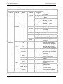
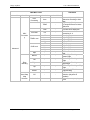
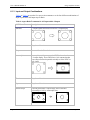
User’s Manual 0020D1.01
Image AnyPlace IA-200
6 Aspect Ratio Treatment
6.1
Aspect Ratio Treatments
The IA-200 provides several different aspect ratio treatments. The operation mode of these
treatments depends on the aspect ratio of the input channel and the output display.
Warning: Aspect ratio treatments are not functional when using custom warp
geometries. If you want to use custom warps with different aspect ratio treatments, you
will have to create a specific warp map for every aspect ratio treatment that you want to
view.
6.1.1 Supported Aspect Ratios
The IA-200 assumes that the aspect ratio of input and output is consistent with the industry
standard definition of the aspect ratio of the particular input signal and video mode. Output aspect
ratio is thus determined by the resolution selected by the user in Setup Mode. Input aspect ratio is
determined by the IA-200 video mode recognition circuitry.
Note: Only two output aspect ratios are supported, 4:3 and 16:9 2 .
Inputs considered to have 4:3 aspect ratio are as follows:
•
•
•
•
Computer Graphics signals with a 4:3 aspect ratio appearing on the DVI and Analog RGB
inputs
SDTV signals (NTSC and PAL derived) appearing on the Composite, S-Video, and
Component inputs
SDTV signals (NTSC and PAL derived) appearing on the SDI input
SDTV signals (NTSC and PAL derived) appearing on the HDMI input
2
The special case of 1280 x 1024 SXGA (an aspect ratio of 5:4) on output is treated as if it were 4:3. The output of a 1280 x 1024
display will be slightly distorted; circles will appear to be vertically oriented ovals. Since the IA-200_EX is intended for wide
screen processing, the 1280 x 1024 SXGA is not a frequently encountered case. Input of 1280 x 1024 will be treated as a pillar
boxed 4:3 signal (i.e. it will have narrow black bars on the Right and Left); aspect ratio of the picture content will be undistorted.
Page 38 of 49
© Flexible Picture Systems