1
Implementing an Out-of-Office
Notification System
Andreas Misje
Master of Science in Engineering Cybernetics
Submission date: July 2013
Supervisor:
Amund Skavhaug, ITK
Norwegian University of Science and Technology
Department of Engineering Cybernetics
i
Problem description
In office environments it may be challenging to get hold of colleagues
when they are not in their offices. A simple remedy may be to use
sticky notes explaining one’s absence and for how long. A flaw with
this solution is the lack of being able to update the message and keep
the information up to date.
In previous work a design is proposed for an electronic system that
replaces a name sign, a portrait and absence notes. The device, consisting of a colour LCD display and an Ethernet network connection,
makes it possible for an office occupant to update text on the display remotely. The main use case is keeping co-workers up to date on
one’s absence, but the interactive display opens for other possibilities.
The objective is to make a device based on the proposed design, including both hardware and software. Part of the objective is to base
the system on microcontrollers in order to explore the limits of GUI,
TCP/IP and encryption on resource-limited systems. A lesser-known
family of microcontrollers will be used to gain competence on nonAtmel products at the Department of Engineering Cybernetics.
The main tasks will be to
• Evaluate the already suggested design and make necessary
changes
• Design and implement the necessary specialised hardware
• Evaluate hardware
• As available time permits, develop software that will fulfill
selected use cases and requirements in the design
• Evaluate the usability and stability of a TCP/IP stack with
SSL/TLS on a resource-constrained microcontroller system
• Evaluate the system as a whole
• Make a description of how the work should be continued
The work shall be undertaken with continuation by others in mind.
Supervisor: Associate professor Amund Skavhaug, Department of
Engineering Cybernetics
iii
Summary
In some office environments it is natural to visit someone in their office
without having an appointment. In such cases it can be frustrating
to find someone to be unexpectedly absent without any information
about why and for how long. This thesis presents a solution to this
problem with a device mounted on the office occupant’s door, giving
guests information about his or her absence. The device has a large
display and is remote controlled, so that the information can be kept
up to date at all times.
The motivation behind creating this device comes from experiencing
the problem first-hand: As a student it can be challenging to guess the
right time to visit one’s supervisor’s office to find the person present.
With the presented system, students will no longer have to continuously visit a closed door, and professors will not have to answer calls
all day explaining their absence.
The thesis starts with describing the out-of-office problem, continues with presenting a design of a solution, the process of making a
prototype with necessary hardware and software, and suggestions for
further development. The project will use microcontrollers in order to
test the capabilities of resource-constrained systems. A 16-bit and a
32-bit microcontroller will run a full TCP/IP stack with SSL support
for a web interface, and drive a WQVGA LCD display with capacitive touch and run a graphical user interface. In order to broaden
the Department of Engineering Cybernetics’s experience with solutions other than those from Atmel, Microchip’s microcontrollers and
development tools will be used to implement the system.
Time will not permit completing the whole system. A hardware prototype is made, complete with necessary drivers and a working HTTP
server, customised for hosting an interactive web interface. A foundation for the remaining software is implemented with suggestions on
how to finish the system.
The results show that it is possible to use microcontrollers to run an
embedded GUI, but that it is cumbersome, and comes with challenges
concerning encoding and fonts. The web server can deliver a throughput of 550 kB/s using a FAT32 file system on a microSD card, which
is sufficient for a single-user web interface. It is less ideal for hosting
iv
web sites for more than a handful of users simultaneously. SSL with
2048-bit keys is possible, although it will add a three second delay
to any HTTPS connection due to the computationally heavy RSA
decryption. The throughput using HTTPS is measured at 317 kB/s,
using 128-bits ARCFOUR. This works well to secure an authentication step, but the throughput is not optimal for securing all HTTP
traffic.
The results prove that the selected microcontrollers are capable of
running a GUI and a secure web server, but the performance is only
good enough for undemanding applications. It would be preferable
to have a better-performing web server. The system may be too
complex for an microcontroller approach, and it should be considered
for further work to look into solutions using an embedded Linux.
v
Sammendrag
I enkelte arbeidsmiljøer er det vanlig å oppsøke hverandre på kontoret
uten å måtte ha en avtale. I slike miljøer kan det være frustrerende
når den du prøver å få tak i ikke er tilstede, og det er ingen informasjon om hvorfor vedkommende er borte og hvor lenge. Dette er ikke
en uvanlig situasjon på universitet, hvor studenter stadig forsøker å
få tak i veiledere og professorer, men ofte blir møtt med en låst dør.
Det er akkurat slike opplevelser som er motivasjonen bak løsningen
presentert i denne oppgaven.
Løsningen er i form av et apparat med en fargeberøringsskjerm og
nettverkstilkobling som kan fjernstyres av eieren. Når professoren
må gå i et ærend, kan han oppdatere skjermen med informasjon om
hvorfor han er borte og når han kommer tilbake. Forbipasserende og
besøkende kan holde seg oppdatert om når det passer å besøke vedkommende, og professoren slipper å motta anrop om spørsmål om når
han aller hun kommer tilbake.
Oppgaven tar for seg prosessen fra idé til prototype, og inkluderer
beskrivelse av problemet, design av løsningen, komponentvalg og
PCB-design, utvikling av programvare og råd og forslag for videre
utvikling. Istedenfor å bruke en embedded Linux-plattform har det
blitt valgt å bruke mikrokontrollere, med mål om å teste mulighetene
for TCP/IP and SSL i ressursbegrensete systemer. En 16- og en
32-bits mikrokontroller blir brukt til å kjøre en vevtjener med støtte
for kryptering, samt drifte en WQVGA-fargeberøringsskjerm med et
grafisk grensesnitt. Det er også valgt å bruke Microchip-løsninger
fremfor produkter fra Atmel, slik at Institutt for teknisk kybernetikk
kan tilegne seg kunnskap om andre, mindre kjente produsenter.
Det er ikke mulig å fullføre systemet på grunn av begrenset mengde
tid tilgjengelig. Maskinvaren er ferdig utviklet, drivere er laget og
en TCP/IP-stakk med en modifisert HTTP-tjener er konfigurert og
testet. Et fundament for de resterende programvarekomponentene er
på plass, og det er gitt råd og forslag for videre utvikling.
Resultatene fra arbeidet viser at det er mulig å lage grafiske grensesnitt på en 16-bits mikrokontroller, men ikke uten utfordringer. Det
er tungvint å utvikle og byr på utfordringer hva angår skrifttyper og
tegnsett. Resultater fra tester av vevtjeneren sammen med et FAT32filsystem og et microSD-minnekort viser at systemet er i stand til å
vi
levere data med en hastighet på 550 kB/s. Dette var nok for å kjøre
et enkeltbrukervevgrensesnitt, men hastigheten er ikke bra nok for å
levere nettsider til mer enn en håndfull klienter om gangen. Mikrokontrolleren klarte å tilby SSL med 2048-bit store nøkler, men det tok så
lenge som tre sekunder å dekode RSA. HTTPS-hastigheten lå stabilt
på 317 kB/s ved bruk av 128-bit ARCFOUR, noe som er marginalt
raskt nok for å kunne kryptere all HTTP-trafikk.
Resultatene viser at mikrokontrollerne lever akkurat gode nok resultater for formålet, men det bør vurderes å velge en embedded Linuxplattform for videre arbeid.
Contents
Contents
vii
List of Figures
xiii
List of Tables
xvii
List of Acronyms
xxiii
I Introduction
1
1
2
Introduction
1.1 Background . . . . . .
Choice of architecture
1.2 Scope . . . . . . . . .
1.3 Outline of the thesis .
.
.
.
.
.
.
.
.
.
.
.
.
.
.
.
.
.
.
.
.
.
.
.
.
.
.
.
.
.
.
.
.
.
.
.
.
.
.
.
.
.
.
.
.
.
.
.
.
.
.
.
.
.
.
.
.
.
.
.
.
.
.
.
.
.
.
.
.
.
.
.
.
3
4
5
6
6
Specification and system design
2.1 Areas of application . . . . . . . .
2.2 Main components . . . . . . . . . .
Display and GUI . . . . . . . . . .
Network connection and web server
NFC reader . . . . . . . . . . . . .
2.3 Specification . . . . . . . . . . . . .
Physical dimensions . . . . . . . .
Network . . . . . . . . . . . . . . .
Power supply . . . . . . . . . . . .
Non-volatile memory . . . . . . . .
Display and frame buffer . . . . . .
Microcontrollers . . . . . . . . . .
Time-keeping . . . . . . . . . . . .
User interfaces . . . . . . . . . . .
.
.
.
.
.
.
.
.
.
.
.
.
.
.
.
.
.
.
.
.
.
.
.
.
.
.
.
.
.
.
.
.
.
.
.
.
.
.
.
.
.
.
.
.
.
.
.
.
.
.
.
.
.
.
.
.
.
.
.
.
.
.
.
.
.
.
.
.
.
.
.
.
.
.
.
.
.
.
.
.
.
.
.
.
.
.
.
.
.
.
.
.
.
.
.
.
.
.
.
.
.
.
.
.
.
.
.
.
.
.
.
.
.
.
.
.
.
.
.
.
.
.
.
.
.
.
.
.
.
.
.
.
.
.
.
.
.
.
.
.
.
.
.
.
.
.
.
.
.
.
.
.
.
.
.
.
.
.
.
.
.
.
.
.
.
.
.
.
.
.
.
.
.
.
.
.
.
.
.
.
.
.
.
.
.
.
.
.
.
.
.
.
.
.
.
.
.
.
.
.
.
.
.
.
.
.
.
.
.
.
.
.
.
.
.
.
.
.
.
.
.
.
.
.
.
.
.
.
.
.
.
.
.
.
.
.
.
.
9
10
11
11
13
13
14
14
14
15
15
16
16
17
17
.
.
.
.
.
.
.
.
.
.
.
.
.
.
.
.
.
.
.
.
.
.
.
.
vii
viii
CONTENTS
2.4
Final design . . . . . . . . . . . . . . . . . . . . . . . . . . . . . .
Design process . . . . . . . . . . . . . . . . . . . . . . . . . . . .
II Hardware
3
4
5
6
7
17
19
21
Development boards
3.1 PIC24FJ256DA210 development board . . . . . .
3.2 Graphics Display PowerTip 4.3 " 480x272 Board
3.3 PIC32MX695F512L board . . . . . . . . . . . . .
3.4 ENC28J60 board . . . . . . . . . . . . . . . . . .
3.5 microSD board . . . . . . . . . . . . . . . . . . .
.
.
.
.
.
.
.
.
.
.
.
.
.
.
.
.
.
.
.
.
.
.
.
.
.
.
.
.
.
.
.
.
.
.
.
.
.
.
.
.
.
.
.
.
.
23
23
24
24
26
26
Microcontrollers
4.1 Communication protocols . .
4.2 PIC24FJ256DA210 . . . . . .
EPMP . . . . . . . . . . . . .
Integrated graphics controller
Allocating pins . . . . . . . .
Necessary connections . . . .
4.3 PIC32MX695F512L . . . . .
Allocating pins . . . . . . . .
Necessary connections . . . .
4.4 Erratas . . . . . . . . . . . .
.
.
.
.
.
.
.
.
.
.
.
.
.
.
.
.
.
.
.
.
.
.
.
.
.
.
.
.
.
.
.
.
.
.
.
.
.
.
.
.
.
.
.
.
.
.
.
.
.
.
.
.
.
.
.
.
.
.
.
.
.
.
.
.
.
.
.
.
.
.
.
.
.
.
.
.
.
.
.
.
.
.
.
.
.
.
.
.
.
.
.
.
.
.
.
.
.
.
.
.
.
.
.
.
.
.
.
.
.
.
.
.
.
.
.
.
.
.
.
.
.
.
.
.
.
.
.
.
.
.
.
.
.
.
.
.
.
.
.
.
29
30
31
32
33
33
34
34
35
36
36
Ethernet
5.1 MII and RMII . . . . . . . . . . . . . . .
5.2 LAN8720 . . . . . . . . . . . . . . . . . .
Configuration straps . . . . . . . . . . . .
Power . . . . . . . . . . . . . . . . . . . .
LEDs, RMII and crystal . . . . . . . . . .
5.3 Connector and transformers . . . . . . . .
5.4 PCB placement and layout considerations
.
.
.
.
.
.
.
.
.
.
.
.
.
.
.
.
.
.
.
.
.
.
.
.
.
.
.
.
.
.
.
.
.
.
.
.
.
.
.
.
.
.
.
.
.
.
.
.
.
.
.
.
.
.
.
.
.
.
.
.
.
.
.
.
.
.
.
.
.
.
.
.
.
.
.
.
.
.
.
.
.
.
.
.
.
.
.
.
.
.
.
37
37
38
39
40
41
41
42
Non-volatile memory
6.1 microSD card . . . . .
Necessary connections
6.2 Parallel flash . . . . .
Necessary connections
.
.
.
.
.
.
.
.
.
.
.
.
.
.
.
.
.
.
.
.
.
.
.
.
.
.
.
.
.
.
.
.
.
.
.
.
.
.
.
.
.
.
.
.
.
.
.
.
.
.
.
.
45
45
46
46
47
Graphics and display
7.1 Display capacitive touch controller . . . . . . . . . . . . . . . . .
49
49
.
.
.
.
.
.
.
.
.
.
.
.
.
.
.
.
.
.
.
.
.
.
.
.
.
.
.
.
.
.
.
.
.
.
.
.
.
.
.
.
.
.
.
.
.
.
.
.
.
.
.
.
.
.
.
.
.
.
.
.
.
.
.
.
.
.
.
.
.
.
.
.
.
.
.
.
.
.
.
.
.
.
.
.
.
.
.
.
.
.
.
.
.
.
.
.
.
.
.
.
.
.
.
.
CONTENTS
7.2
ix
.
.
.
.
.
.
.
50
50
51
52
53
56
57
8
Power over Ethernet
8.1 Inrush current limiter . . . . . . . . . . . . . . . . . . . . . . . .
8.2 PoE controller and DC–DC converter . . . . . . . . . . . . . . .
61
61
62
9
Near-field communication
9.1 PN532 . . . . . . . . . . . . . . . . . . . . . . . . . . . . . . . . .
65
66
7.3
7.4
7.5
Display prototyping adapter . . . . .
LED driver design . . . . . . . . . .
Connecting RGB and control signals
PCB design . . . . . . . . . . . . . .
SRAM . . . . . . . . . . . . . . . . .
Double buffering . . . . . . . . . . .
PCB design considerations . . . . . .
10 PCB design and assembly
10.1 Software tools used . . . . . . .
10.2 Finalising circuit . . . . . . . .
10.3 Placing components . . . . . .
10.4 Finished design . . . . . . . . .
10.5 Fabrication . . . . . . . . . . .
Results . . . . . . . . . . . . . .
10.6 Assembly . . . . . . . . . . . .
10.7 Testing and verification . . . .
Inrush current limiter problem
LAN8720 crystal problem . . .
Buzzer not working . . . . . . .
Unresolved parallel flash issues
.
.
.
.
.
.
.
.
.
.
.
.
.
.
.
.
.
.
.
.
.
.
.
.
.
.
.
.
.
.
.
.
.
.
.
.
.
.
.
.
.
.
.
.
.
.
.
.
.
.
.
.
.
.
.
.
.
.
.
.
.
.
.
.
.
.
.
.
.
.
.
.
.
.
.
.
.
.
.
.
.
.
.
.
.
.
.
.
.
.
.
.
.
.
.
.
.
.
.
.
.
.
.
.
.
.
.
.
.
.
.
.
.
.
.
.
.
67
67
68
68
70
71
72
73
73
74
75
76
77
11 Hardware: Discussion
11.1 Component selection . . . . . . . . . . . . . . . . . . . . . . . . .
11.2 Design flaws and improvements . . . . . . . . . . . . . . . . . . .
11.3 Missing NFC integration . . . . . . . . . . . . . . . . . . . . . . .
79
79
80
81
12 Hardware: Conclusion
83
III Software
85
13 Architecture
13.1 Operating system . . . . . . . . . . . . . . . . . . . . . . . . . . .
13.2 Choosing libraries . . . . . . . . . . . . . . . . . . . . . . . . . .
87
88
89
.
.
.
.
.
.
.
.
.
.
.
.
.
.
.
.
.
.
.
.
.
.
.
.
.
.
.
.
.
.
.
.
.
.
.
.
.
.
.
.
.
.
.
.
.
.
.
.
.
.
.
.
.
.
.
.
.
.
.
.
.
.
.
.
.
.
.
.
.
.
.
.
.
.
.
.
.
.
.
.
.
.
.
.
.
.
.
.
.
.
.
.
.
.
.
.
.
.
.
.
.
.
.
.
.
.
.
.
.
.
.
.
.
.
.
.
.
.
.
.
.
.
.
.
.
.
.
.
.
.
.
.
.
.
.
.
.
.
.
.
.
.
.
.
.
.
.
.
.
.
.
.
.
.
.
.
.
.
.
.
.
.
.
.
.
.
.
.
.
.
.
.
.
.
.
.
.
.
.
.
.
.
.
.
.
.
.
.
.
.
.
.
.
.
.
.
.
.
.
.
.
.
.
.
.
.
.
.
.
.
.
.
.
.
.
.
x
CONTENTS
Licenses . . . . . . . . . . . . . . . . . . . . . . . . . . . . . . . .
14 Development environment
14.1 Microchip compilers and IDE . . . .
Microchip software libraries . . . . .
XC32 and XC16 peripheral libraries
14.2 Setting up a local network . . . . . .
89
.
.
.
.
.
.
.
.
.
.
.
.
.
.
.
.
.
.
.
.
.
.
.
.
.
.
.
.
.
.
.
.
.
.
.
.
.
.
.
.
.
.
.
.
91
91
92
93
93
15 File system
15.1 How the library works . . . . . . . . . . . . . .
Configuring FatFS . . . . . . . . . . . . . . . .
I/O layer implementation and configuration . .
Modifications to the I/O layer implementation
15.2 Performance . . . . . . . . . . . . . . . . . . . .
How the read test is performed . . . . . . . . .
Results . . . . . . . . . . . . . . . . . . . . . . .
15.3 File system structure . . . . . . . . . . . . . . .
.
.
.
.
.
.
.
.
.
.
.
.
.
.
.
.
.
.
.
.
.
.
.
.
.
.
.
.
.
.
.
.
.
.
.
.
.
.
.
.
.
.
.
.
.
.
.
.
.
.
.
.
.
.
.
.
.
.
.
.
.
.
.
.
.
.
.
.
.
.
.
.
.
.
.
.
.
.
.
.
97
98
98
99
102
105
105
105
107
16 Touch controller driver
16.1 I2 C driver . . . . . . . . . . . . . . . . . . . . . . . . . . . . . . .
16.2 FT5x06 driver . . . . . . . . . . . . . . . . . . . . . . . . . . . . .
16.3 GOL interfacing . . . . . . . . . . . . . . . . . . . . . . . . . . .
109
110
111
113
17 Parallel flash driver
17.1 Accessing external memory using EDS . . . . . . . . . . . . . . .
17.2 EPMP bypass mode . . . . . . . . . . . . . . . . . . . . . . . . .
17.3 Problems . . . . . . . . . . . . . . . . . . . . . . . . . . . . . . .
117
117
119
119
18 Graphics library
18.1 Configuration . . . . . . . . . . .
18.2 Using the graphics library . . . .
GOL . . . . . . . . . . . . . . . .
Fonts and other resources . . . .
18.3 Using a state machine with GOL
.
.
.
.
.
121
123
125
125
127
128
19 Calendar and availabilities
19.1 Appointment and availability format . . . . . . . . . . . . . . . .
19.2 File structure . . . . . . . . . . . . . . . . . . . . . . . . . . . . .
19.3 Real-time clock and calendar . . . . . . . . . . . . . . . . . . . .
131
131
132
134
20 TCP/IP stack
20.1 Architecture . . . . . . . . . . . . . . . . . . . . . . . . . . . . . .
135
136
.
.
.
.
.
.
.
.
.
.
.
.
.
.
.
.
.
.
.
.
.
.
.
.
.
.
.
.
.
.
.
.
.
.
.
.
.
.
.
.
.
.
.
.
.
.
.
.
.
.
.
.
.
.
.
.
.
.
.
.
.
.
.
.
.
.
.
.
.
.
.
.
.
.
.
.
.
.
.
.
.
.
.
.
.
.
.
.
.
.
.
.
.
.
.
.
.
.
.
.
.
.
.
.
.
CONTENTS
xi
20.2 Stack configuration . . . . . . . . . . .
Setting MAC and IP addresses . . . .
20.3 Using the stack . . . . . . . . . . . . .
20.4 Modifications . . . . . . . . . . . . . .
20.5 HTTP server . . . . . . . . . . . . . .
How the server works . . . . . . . . . .
FatFS support . . . . . . . . . . . . .
Dynamic variables . . . . . . . . . . .
GET and POST processing . . . . . .
Authentication and authorisation . . .
Configuration . . . . . . . . . . . . . .
Using MPFS to convert files . . . . . .
20.6 SSL . . . . . . . . . . . . . . . . . . .
Generating and using SSL certificates
20.7 SNTP client . . . . . . . . . . . . . . .
Modifications . . . . . . . . . . . . . .
.
.
.
.
.
.
.
.
.
.
.
.
.
.
.
.
.
.
.
.
.
.
.
.
.
.
.
.
.
.
.
.
.
.
.
.
.
.
.
.
.
.
.
.
.
.
.
.
.
.
.
.
.
.
.
.
.
.
.
.
.
.
.
.
.
.
.
.
.
.
.
.
.
.
.
.
.
.
.
.
.
.
.
.
.
.
.
.
.
.
.
.
.
.
.
.
.
.
.
.
.
.
.
.
.
.
.
.
.
.
.
.
.
.
.
.
.
.
.
.
.
.
.
.
.
.
.
.
.
.
.
.
.
.
.
.
.
.
.
.
.
.
.
.
.
.
.
.
.
.
.
.
.
.
.
.
.
.
.
.
.
.
.
.
.
.
.
.
.
.
.
.
.
.
.
.
.
.
.
.
.
.
.
.
.
.
.
.
.
.
.
.
.
.
.
.
.
.
.
.
.
.
.
.
.
.
.
.
.
.
.
.
.
.
.
.
.
.
.
.
.
.
.
.
.
.
.
.
.
.
.
.
.
.
.
.
.
.
.
.
139
139
139
140
141
141
144
146
148
151
153
155
155
157
158
158
21 Inter-microcontroller communication
161
22 Other modules and software
22.1 Settings . . . . . . . .
22.2 Tick module . . . . . .
22.3 UART and debugging
22.4 NFC reader . . . . . .
.
.
.
.
.
.
.
.
.
.
.
.
.
.
.
.
.
.
.
.
.
.
.
.
.
.
.
.
.
.
.
.
.
.
.
.
.
.
.
.
.
.
.
.
165
165
166
167
168
interface
Limitations and considerations . . . . . . . . .
Frontend . . . . . . . . . . . . . . . . . . . . . .
Selecting application framework . . . . . . . . .
Development environment . . . . . . . . . . . .
Outline of a page with jQuery Mobile . . . . .
Web interface menu structure . . . . . . . . . .
23.6 Encoding considerations and bilingual support
.
.
.
.
.
.
.
.
.
.
.
.
.
.
.
.
.
.
.
.
.
.
.
.
.
.
.
.
.
.
.
.
.
.
.
.
.
.
.
.
.
.
.
.
.
.
.
.
.
.
.
.
.
.
.
.
.
.
.
.
.
.
.
.
.
.
.
.
.
.
169
169
171
172
173
174
176
183
24 Software: Discussion
24.1 TCP/IP stack . . . . . . . . . . . . . . . . . . . . . . . . . . . . .
24.2 Web development . . . . . . . . . . . . . . . . . . . . . . . . . . .
24.3 GUI development . . . . . . . . . . . . . . . . . . . . . . . . . . .
185
185
186
186
25 Software: Conclusion
189
23 Web
23.1
23.2
23.3
23.4
23.5
.
.
.
.
.
.
.
.
.
.
.
.
.
.
.
.
.
.
.
.
.
.
.
.
.
.
.
.
.
.
.
.
.
.
.
.
.
.
.
.
.
.
.
.
.
.
.
.
.
.
.
.
xii
CONTENTS
IV End result
26 Testing and results
26.1 Web server and web UI . . . . .
Robustness and error handling .
Responsiveness and mobile access
Web server performance . . . . .
SSL performance . . . . . . . . .
TCP/IP stack stability . . . . . .
26.2 Display, touch and GUI . . . . .
191
.
.
.
.
.
.
.
.
.
.
.
.
.
.
.
.
.
.
.
.
.
.
.
.
.
.
.
.
.
.
.
.
.
.
.
.
.
.
.
.
.
.
.
.
.
.
.
.
.
.
.
.
.
.
.
.
.
.
.
.
.
.
.
.
.
.
.
.
.
.
.
.
.
.
.
.
.
193
193
193
194
195
197
198
200
27 Discussion and further work
27.1 Development using Microchip microcontrollers
27.2 OOD hardware . . . . . . . . . . . . . . . . . .
27.3 TCPIP and web server performance . . . . . .
27.4 Further work . . . . . . . . . . . . . . . . . . .
.
.
.
.
.
.
.
.
.
.
.
.
.
.
.
.
.
.
.
.
.
.
.
.
.
.
.
.
.
.
.
.
.
.
.
.
.
.
.
.
201
201
202
202
202
.
.
.
.
.
.
.
.
.
.
.
.
.
.
.
.
.
.
.
.
.
.
.
.
.
.
.
.
.
.
.
.
.
.
.
.
.
.
.
.
.
.
.
.
.
.
.
.
.
28 Conclusion
205
References
207
V Appendix
213
A Source code
A.1 MAL patch . . . . . . . . . . . . . . . . . . . . . . . . . . . . . .
A.2 HTTP server patch . . . . . . . . . . . . . . . . . . . . . . . . . .
A.3 FatFS read test . . . . . . . . . . . . . . . . . . . . . . . . . . . .
215
215
216
216
B Pin allocation tables
217
C Schematic circuit diagrams
225
D Bill of materials
235
List of Figures
1.1
A simple out-of-office system . . . . . . . . . . . . . . . . . . . . . .
2.1
2.2
2.3
2.4
2.5
The OOD mounted next to an office door . . . . . .
The OOD’s interactions . . . . . . . . . . . . . . . .
Main sections of the default menu/page . . . . . . .
OOD in a plastic housing with expected dimensions
The design process . . . . . . . . . . . . . . . . . . .
.
.
.
.
.
.
.
.
.
.
.
.
.
.
.
.
.
.
.
.
.
.
.
.
.
.
.
.
.
.
.
.
.
.
.
.
.
.
.
.
.
.
.
.
.
9
10
12
18
20
3.1
3.2
3.3
3.4
3.5
The PIC24FJ256DA210 development board
The PowerTip display development board .
The PIC32 development board . . . . . . .
ENC28J60 development board . . . . . . .
microSD development board . . . . . . . . .
.
.
.
.
.
.
.
.
.
.
.
.
.
.
.
.
.
.
.
.
.
.
.
.
.
.
.
.
.
.
.
.
.
.
.
.
.
.
.
.
.
.
.
.
.
24
25
25
26
27
4.1
4.2
4.3
4.4
4.5
All the components in the ODD and how they are connected
PIC24F architecture . . . . . . . . . . . . . . . . . . . . . . .
Recommended minimum connections for PIC24F . . . . . . .
PIC32MX architecture . . . . . . . . . . . . . . . . . . . . . .
Recommended minimum connections for PIC32 . . . . . . . .
.
.
.
.
.
.
.
.
.
.
.
.
.
.
.
.
.
.
.
.
29
32
34
35
36
5.1
5.2
5.3
5.4
LAN8720 pin-out . . . . . . . . . . . . . . . .
LAN8720 power circuit diagram . . . . . . .
LAN8720 circuit diagram – RMII and LEDs .
Height of the TM25RS 8P8C connector . . .
.
.
.
.
.
.
.
.
.
.
.
.
.
.
.
.
39
40
41
42
6.1
6.2
6.3
microSD card pin-out . . . . . . . . . . . . . . . . . . . . . . . . . .
microSD card slot circuit diagram . . . . . . . . . . . . . . . . . . .
Parallel flash circuit diagram . . . . . . . . . . . . . . . . . . . . . .
45
47
48
7.1
7.2
7.3
PCIe x4 PCB connector . . . . . . . . . . . . . . . . . . . . . . . . .
LED driver schematic . . . . . . . . . . . . . . . . . . . . . . . . . .
Signal lines between the display and the PIC24 microcontroller . . .
50
51
52
.
.
.
.
.
.
.
.
.
.
.
.
.
.
.
.
.
.
.
.
.
.
.
.
.
.
.
.
.
.
.
.
.
.
.
.
.
.
.
.
.
.
.
.
.
.
.
.
.
.
.
.
.
.
.
.
.
.
.
.
.
3
xiii
xiv
LIST OF FIGURES
7.4
7.5
7.6
7.7
7.8
Display to development board adapter . . . . . .
Milled PCB with components and display fitted .
SRAM circuit diagram . . . . . . . . . . . . . . .
How double buffering works . . . . . . . . . . . .
Display’s position and cable attachment . . . . .
.
.
.
.
.
.
.
.
.
.
54
55
56
58
59
8.1
Inrush current limiter circuit diagram . . . . . . . . . . . . . . . . .
62
9.1
The PN532 board . . . . . . . . . . . . . . . . . . . . . . . . . . . .
65
10.1
10.2
10.3
10.4
10.5
10.6
10.7
10.8
10.9
Suggested component placement . . . . . . . . . .
The finished PCB design . . . . . . . . . . . . . . .
Close-up of the EPMP signals in the PCB design .
Close-up of the Ethernet signals in the PCB design
Close-up of the PIC24 TQFP pad pitch . . . . . .
PCB from the manufacturer . . . . . . . . . . . . .
The assembled OOD prototype – upper side . . . .
Inrush current limiter fix . . . . . . . . . . . . . .
LAN8720 crystal fix . . . . . . . . . . . . . . . . .
.
.
.
.
.
.
.
.
.
69
70
71
72
73
74
75
76
76
11.1 The incorrect placement of the large components . . . . . . . . . . .
11.2 0402 resistor footprint and resistor . . . . . . . . . . . . . . . . . . .
79
81
13.1 OOD software architecture . . . . . . . . . . . . . . . . . . . . . . .
87
14.1 ICSP pin-out (seen at PICkit 3 programmer) . . . . . . . . . . . . .
14.2 MAL file structure . . . . . . . . . . . . . . . . . . . . . . . . . . . .
92
93
15.1 FatFS architecture . . . . . . . . . . . . . . . . . . . . . . . . . . . .
97
16.1 Architecture of the touch driver . . . . . . . . . . . . . . . . . . . . .
109
18.1
18.2
18.3
18.4
Microchip graphics library architecture . . . . . . .
Currently active GUI objects chain in a linked list
The Graphics Resource Converter . . . . . . . . .
State machine features . . . . . . . . . . . . . . . .
.
.
.
.
.
.
.
.
.
.
.
.
.
.
.
.
.
.
.
.
.
.
.
.
.
.
.
.
.
.
.
.
.
.
.
.
.
.
.
.
121
122
127
129
20.1
20.2
20.3
20.4
20.5
Architecture of Microchip’s TCP/IP stack . . . .
Protocol dependencies in the various OSI layers .
HTTP server state diagram . . . . . . . . . . . .
How adding and checking passwords is performed
The MPFS2 HTML converter . . . . . . . . . . .
.
.
.
.
.
.
.
.
.
.
.
.
.
.
.
.
.
.
.
.
.
.
.
.
.
.
.
.
.
.
.
.
.
.
.
.
.
.
.
.
.
.
.
.
.
.
.
.
.
.
136
137
142
152
156
.
.
.
.
.
.
.
.
.
.
.
.
.
.
.
.
.
.
.
.
.
.
.
.
.
.
.
.
.
.
.
.
.
.
.
.
.
.
.
.
.
.
.
.
.
.
.
.
.
.
.
.
.
.
.
.
.
.
.
.
.
.
.
.
.
.
.
.
.
.
.
.
.
.
.
.
.
.
.
.
.
.
.
.
.
.
.
.
.
.
.
.
.
.
.
.
.
.
.
.
.
.
.
.
.
.
.
.
.
.
.
.
.
.
.
.
.
.
.
.
.
.
.
.
.
.
.
.
.
.
.
LIST OF FIGURES
xv
21.1 Sequence diagram of a name query sent by the master . . . . . . . .
163
22.1 UART to RS-232 level converter adapter . . . . . . . . . . . . . . . .
22.2 USB–UART bridge . . . . . . . . . . . . . . . . . . . . . . . . . . . .
167
168
23.1
23.2
23.3
23.4
23.5
23.6
23.7
23.8
How a request from the client is handled in the web server
Web UI menu structure . . . . . . . . . . . . . . . . . . .
Interactive calendar for adding appointments . . . . . . .
Availability type configuration . . . . . . . . . . . . . . . .
Editing colours in availability type configuration . . . . .
Name and title configuration page in web UI . . . . . . .
Network configuration page in web UI . . . . . . . . . . .
Time and date configuration page in web UI . . . . . . . .
.
.
.
.
.
.
.
.
.
.
.
.
.
.
.
.
.
.
.
.
.
.
.
.
.
.
.
.
.
.
.
.
.
.
.
.
.
.
.
.
.
.
.
.
.
.
.
.
170
176
177
178
179
180
181
182
26.1
26.2
26.3
26.4
SSL handshake duration (Wireshark screenshot) . . .
SSL handshake duration with saved session . . . . . .
Client hello and server hello packets with same session
GUI main page mock-up on development board . . . .
.
.
.
.
.
.
.
.
.
.
.
.
.
.
.
.
.
.
.
.
.
.
.
.
198
198
199
200
. .
. .
ID
. .
List of Tables
5.1
RMII signals . . . . . . . . . . . . . . . . . . . . . . . . . . . . . . .
38
6.1
microSD card pin-out . . . . . . . . . . . . . . . . . . . . . . . . . .
45
7.1
LED driver BOM . . . . . . . . . . . . . . . . . . . . . . . . . . . . .
52
8.1
Maximum operating currents per device . . . . . . . . . . . . . . . .
63
15.1 FatFS configuration . . . . . . . . . . . . . . . . . . . . . . . . . . .
15.2 Required user-implemented functions in FatFS . . . . . . . . . . . .
15.3 The file system structure seen from the root directory (/) . . . . . .
99
100
108
16.1 Excerpt of FT5x06 operating mode register map . . . . . . . . . . .
113
20.1
20.2
20.3
20.4
.
.
.
.
137
147
147
149
21.1 Inter-microcontroller communication packet format . . . . . . . . . .
161
23.1 User reactions to various web page delays . . . . . . . . . . . . . . .
23.2 Format of data returned from availability query functions . . . . . .
172
179
26.1 Multiple connection throughput results . . . . . . . . . . . . . . . .
26.2 10 concurrent users, 10 repetitions using a 10 kB file . . . . . . . . .
196
197
A.1 Source code contents . . . . . . . . . . . . . . . . . . . . . . . . . . .
215
Files needed from the TCP/IP stack
Format of FileRcrd.bin . . . . . . . .
Format of DynRcrd.bin . . . . . . .
HTTP_IO_RESULT return values .
.
.
.
.
.
.
.
.
.
.
.
.
.
.
.
.
.
.
.
.
.
.
.
.
.
.
.
.
.
.
.
.
.
.
.
.
.
.
.
.
.
.
.
.
.
.
.
.
.
.
.
.
.
.
.
.
.
.
.
.
.
.
.
.
.
.
.
.
xvii
List of Acronyms
ACL access control list
AJAX asynchronous JavaScript and XML
API application programming interface
ARP address resolution protocol
ASCII American Standard Code for Information Interchange
BCD binary-coded decimal
BGA ball grid array
BOM bill of materials
BSD Berkely Software Distribution
CD compact disk
CGI common gateway interface
CPU central processing unit
CSR certificate signing request
CSS cascading style sheets
DC direct current
DHCP dynamic host configuration protocol
DMA direct memory access
DNS domain name system
ECAD electronic design automation
EDS extended data space
xix
xx
EMC electromagnetic compatibility
ENIG electroless nickel immersion gold
EPMP enhanced parallel master port
FAT file allocation table
GOL graphics object layer
GPL GNU General Public License
GPU graphical processing unit
GRC Graphics Resource Converter
GUI graphical user interface
HTML hypertext markup language
HTTP hypertext transfer protocol
HTTPS hypertext transfer protocol secure
I2 C inter-intergrated circuit
IC integrated circuit
ICMP Internet control message protocol
ICSP in-circuit serial programming
IDE integrated development environment
IP Internet protocol
IPv4 Internet protocol version 4
IPv6 Internet protocol version 6
ITEM the Department of Telematics
ITK the Department of Engineering Cybernetics
JSON JavaScript object notation
LCD liquid crystal display
LED light-emitting diode
LIST OF ACRONYMS
LIST OF ACRONYMS
LFN long filename
LGPL GNU Lesser General Public License
LSB least significant bit
MAC media access control
MAL Microchip application libraries
MDD (Microchip) Memory Disk Drive (File System Library)
MDIX media dependent interface crossover
MII media independent interface
MIPS million instructions per second
MIT Massachusetts Institute of Technology
MSB most significant bit
NFC near field communication
NTNU the Norwegian University of Science and Technology
NTP network time protocol
OEM original equipment manufacturer
ONFI Open NAND Flash Interface Working Group
OOD out-of-office display
OS operating system
OSI Open Systems Interconnection
OTG on-the-go
PCB (electronics) printed circuit board
PCIe peripheral component interconnect express
PD powered device
PLL phase-locked loop
PoE power over Ethernet
xxi
xxii
PSE power-sourcing equipment
PWM pulse-width modulation
QFN quad-flat no-leads
QVGA quarter video graphics array
RAM random-access memory
RFID radio-frequency identification
RGB red green blue
RMII reduced media independent interface
RTC real-time clock
RTCC real-time calendar/clock
RTOS real-time operating system
SD Secure Digital
SNTP simple network time protocol
SPI serial peripheral interface bus
SRAM static random-access memory
SSL secure sockets layer
TCP transmission control protocol
TCP/IP the Internet protocol suite
TFT thin film transistor
TLS transport layer security
TP twisted pair
TQFP thin quad flat package
TSOP thin small-outline package
TSOP II thin small-outline package type II
UART universal asynchronous receiver/transmitter
LIST OF ACRONYMS
LIST OF ACRONYMS
UDP user datagram protocol
UI user interface
URL uniform resource locator
USB universal serial bus
UTC coordinated universal time
VGA video graphics array
xxiii
Part I
Introduction
1
Introduction
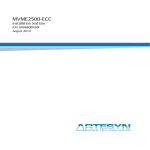
Figure 1.1: A simple out-of-office system
Professors are at times very hard to get hold of. So is reliable information about
when they will be back at their offices. Wandering the hallways of a university
will reveal many doors with sticky notes and the occasional home-grown out-ofoffice information system with spinning dials or arrays of LEDs. Although many
of these simple systems fulfil one important need: tell people that one is away
and when one is likely to return, they all lack the possibility to be updated whilst
being away. Information about one’s availability has little value if it is outdated
and incorrect.
With an ability to update the message on the door remotely, coworkers and
students no longer need to periodically visit the professor’s office door to check
for his presence. Knowing that the information is up to date and can be trusted,
3
4
CHAPTER 1. INTRODUCTION
students and coworkers can return when the professor has announced his arrival.
If the system also allows the professor to update his availability status in a very
efficient manner, chances are he will always notify his coworkers and students
whenever he disappears, even for short errands.
This scenario is not limited to universities. In office environments where it is
common to seek one another without having an appointment, it can be frustrating
having to frequently visit empty offices hoping to get hold of someone. The main
motivation for developing an electronic out-of-office system does, however, come
from an academic environment. From the author’s personal experience, it can be
very difficult to get hold of certain academic employees. Sometimes the best way
to get hold of an employee at the department is to meet up at their office. When
the door is locked and coworkers can assure you that the person concerned is
present somewhere on the premises, the author has missed a way to be informed
more accurately about their absence. In the case the person in question is absent
for hours, perhaps in a meeting, unable to answer calls, being informed about
the absence would eliminate the need to constantly meet up at the door to see if
the employee is back.
Although the presented problem may seem piffling to some, the suggested
solution may prove to be a great aid in improving communication between workers
in an office environment. Having a display next to the door can also eliminate
the need for a name sign, and a portrait where needed, making the process of
updating and replacing these easy.
1.1
Background
In Preliminary Design of an Out-of-Office Information System [66] the out-ofoffice problem was studied, and a design of a system that aimed to solve the
problem was presented. The system was named “out-of-office display (OOD)”
and had the following suggested features
A colour TFT LCD touch display dimensioned to contain availability information as well as the office occupant’s name and portrait. The touch interface
allows passer-bys to interact with the system and access additional menus
and features.
An Ethernet network connection that connects the OOD to the office network
or Internet, allowing the owner to update information remotely. The device
also optionally hosts a public web site where the current availability status
can be read. This eliminates the need to go to the office door to check for
the updated information on absence.
1.1. BACKGROUND
5
Power provided by power over Ethernet (PoE) which eliminates the need for
battery replacement, and reduces cabling to one cable for both power and
network.
The design [66] also included thorough theory on PoE, which was used to design
power supply circuitry. The remaining main hardware components were selected
based on the specifications, and main software libraries were suggested.
Choice of architecture
In the design [66] a somewhat unconventional method was used to select the
system architecture and type and family of microcontrollers: The manufacturer
was chosen first. The reason behind this was an objective of gaining knowledge of
a lesser-known family of microcontrollers. The Norwegian University of Science
and Technology (NTNU) has a lot of development equipment and easy access to
products from Atmel. Although there is nothing wrong with Atmel’s solutions,
it would be beneficial for the Department of Engineering Cybernetics (ITK) to
explore the solutions from other major manufacturers. Microchip was chosen
because it has a series of interesting 32- and 16-bit microcontrollers and crossplatform development equipment. Hopefully the results presented in this thesis
will act as useful knowledge for some of the microcontrollers, development tools
and software libraries from Microchip.
Choosing a specific manufacturer is one of the architectural decisions. The
other major decision is the choice of using microcontrollers instead of solutions
that can run operating systems, like an embedded version of Linux. Using an
open-source full-blown operating system would possibly eliminate a lot of lowlevel code used to interface hardware, and could shift the focus towards writing
the main application aimed to solve the “out-of-office problem”. There would be
no need to fiddle with a TCP/IP stack: Linux comes with a well-tested and robust
implementation, and frameworks like Qt1 would make it a lot less cumbersome
to write a GUI to the display.
A microcontroller solution was chosen in favour for an ARM processor with
embedded Linux for two main reasons:
• It would act as useful research to find the limitations and usability of a
TCP/IP stack with cryptographic support running on a system with limited
resources. Can the microcontroller run a stable web server with SSL/TLS
with acceptable performance?
• Since the hardware is to be custom made, it would be more manageable
for a person with very limited experience in PCB design to make a PCB
1 Cross-platform framework in C++ for creating graphical user interfaces (GUIs) [58]
6
CHAPTER 1. INTRODUCTION
with few layers and less complexity. If the design can be restricted to two
layers, it can also potentially be prototyped using the department’s milling
machine, and PCB production would be less expensive.
1.2
Scope
The work presented in this thesis includes a final design of the OOD, a new look
at the specification and requirements, schematics and PCB design, introduction
to Microchip development tools and libraries, and development of user interfaces
(UIs) for both web and the display. With such an array of different topics, some of
the topics will be given more focus than others. Given that one of the objectives
is to explore TCP/IP and SSL on an resource-limited system, the topics related
to TCP/IP are given extra attention. Details are also provided on how to setup a system similar to the development environment used in this project, so
that the results can be reproduced (and improved). The main focus in general
is on software, so more weight is put on describing software, rather than the
hardware. There is therefore not a great level of detail in the chapters discussing
the electronics side of the OOD.
It is expected of the reader to have good knowledge of the programming
language C, a basic understanding of hypertext markup language (HTML),
cascading style sheets (CSS), JavaScript and Linux, and basic knowledge of
electronics. The reader is also expected to have a basic understanding of TCP/IP
and Ethernet. There is no separate chapter on background theory: Necessary
explanations will be given where needed, and more extensive background theory
can be found in [66].
Due to the great extent of the project, there will no time to finish the OOD
as it is presented in the specification. However, there will be sufficient detailed
studies of all the vital components of the system in order to make assesments of
the suggested design. The focus is directed towards making a solid foundation
for further development rather than trying to implement the whole system.
1.3
Outline of the thesis
Before the implementation is discussed, a small repetition from the original
design [66] is given, followed by necessary modifications and improvements. Based
on this a more detailed specification is made, which is used in the following parts
to implement hardware and software. The project is large, so it is necessary to
shorten and exclude certain parts. Some of the chapters are very detailed, like the
chapter on TCP/IP, because it is a part of the main goal to explore the subject.
Part two contains all hardware-related chapters. Each chapter discusses
hardware options for a major function of the OOD. A component fulfilling the
1.3. OUTLINE OF THE THESIS
7
specification is chosen, and any necessary details on how to configure and use the
component is given. Chapter 10, PCB design and assembly, explains the process
of designing the PCB, and discusses the manufactured and assembled result.
Part three starts by explaining the software architecture, how libraries will
be selected, and mentions the importance of software licenses. Chapther 14,
Development environment, briefly mentions how to set up a development
environment similar to the one used when making the OOD. The next chapters
introduce the various software libraries and modules used, and explain how they
work, and how they are configured and used. Small excerpts of code will be
included when explaining the software, but the complete source code will be put
in the appendix. The last chapter in part three, Web interface, explains the
challenges with developing web pages for an embedded web server, the process
behind choosing an application framework and how the web UI is implemented.
Part two and three will be discussed separately, and a conclusion is written
separately for hardware and software. Part four presents results from testing
the web server, followed by a discussion and a conclusion for the end result.
Guidelines and suggestions for further development will be given throughout the
thesis, and summarised at the end.
The progress of any development after this thesis can be found at
http://ood.2tsa.net.
2
Specification and system design
Figure 2.1: The OOD mounted next to an office door
Described in the most simplest terms, the OOD is a small rectangular box housing
a display and circuitry for a network connection and power supply [66, p. 9].
Figure 2.1 is a simple illustration showing how the OOD could be mounted next
to a door. The size of the display should be small enough to not resemble a
9
10
CHAPTER 2. SPECIFICATION AND SYSTEM DESIGN
monitor, but large enough so that it can show text visible from a few metres
away. Its housing should be not much larger than the display itself, and most
importantly, as slim as possible, given that it’s going to be mounted on a wall.
It should be easy to install and require as little cabling as possible.
2.1
Areas of application
Figure 2.2: The out-of-office display (OOD)’s interactions
Figure 2.2 from [66] illustrates how the out-of-office display (OOD) is designed
to interact with its environment. It consists of a local interface: a touch display,
along with a near field communication (NFC) reader, and a remote interface:
the web server. The web interface, built on common protocols, can easily be
interfaced with other devices by using a public application programming interface
(API). A good candidate for this is the hall monitors found at ITK and the
Department of Telematics (ITEM). They are used to show a list of the employees
in the building, their contact info, and where their offices are on the premises.
It would be useful to improve these monitors by including information about the
employees’ presence.
The following examples and scenarios from [66] illustrate how the OOD can
be used:
• The office worker is in a meeting that lasts longer than anticipated. Instead
of having to receive numerous calls from people wondering about his or her
whereabouts, the office worker can discretely update the message on the
display remotely with a smartphone application or a web interface.
2.2. MAIN COMPONENTS
11
• An unforeseen incident prevents the office worker from going to work. In
a matter of seconds, the office worker can update the out-of-office display
with the duration of the absence and a reason.
• The office worker is in a rush and must leave the office quickly. There is
no time to leave a detailed message, but by flicking an ID card in front of
the OOD, a generic absence status will be activated. This action takes no
more than a second, ensuring that the office worker always keeps his or her
status updated regardless of the haste.
• A visitor finds out that the office worker is out of office. The visitor may
have a delivery, a message he or she has not yet written down, or a request to
book a meeting or visit. The visitor can use the display to notify the office
worker about their visit, or book a meeting with an interactive booking
menu that shows when the occupant is occupied or out of office in the
following hours and days.
• Before seeking the office, a visitor can look for the office worker’s availability
online. If the OOD is connected to a larger monitor showing a list of the
department’s employees, their availabilities can be shown here as well. Then
it would not be necessary to go to the office worker’s door to see whether
he or she is present or occupied.
• In environments where the employees frequently change offices, no new
name signs need to be ordered. The name and portrait on the display can
easily be changed.
2.2
Main components
The main components of the OOD are considered to be the three interfaces
and the hardware and software that make them up. What is expected of these
interfaces is described in the following sections.
Display and GUI
The display is the most important part of the OOD. It serves as a replacement for
a name sign, a portrait, and more importantly, it serves up-to-date information
about the availability or absence of the person whose name is on it. In its normal
state (at the root of the menus of the GUI), the display shows the following key
data:
• Name and title
• Portrait (if needed)
12
CHAPTER 2. SPECIFICATION AND SYSTEM DESIGN
Figure 2.3: Main sections of the default menu/page
• Availability
It is not always necessary to display a photo. Removing the picture gives more
room for the name and title. This is designed to be possible to do from the
control panel. The availability field consists of a large font describing the type of
availability, that is whether the office occupant is available, present but busy, at
lunch or away for the day. A second, optional line, describes the status further,
and a duration tells for how long this status is valid. The background colour is
meant to indicate the type of availability: Green would mean that the person
concerned is present and does not mind being disturbed, whereas red or orange
could mean that he or she is absent or busy. These colours shall be for the owner
to choose.
A small portion of the display will also be used to show useful information,
like the current time and information about the network connection (a broken
connection would mean that the information may no longer be up to date and
valid). A touch anywhere on the display, or on a menu button if deemed necessary,
opens the main menu, allowing passer-bys to any of the following:
• Check the office occupant’s public schedule in order to see whether he or
she is available in the near future.
2.2. MAIN COMPONENTS
13
• Notify the office occupant by sending a short notification.
• Book a meeting
Different environments would have different needs, and some OOD owners would
probably not need the possibility of letting passer-bys sending messages and book
appointments from the menus. These menus should be possible to be disabled
and customised. If the menu is abandoned, it should revert to the main page,
showing name, portrait and status after a suitable timeout.
Network connection and web server
The web server serves two purposes: Letting the owner update his status and
configure the OOD, and letting coworkers see his current status without having
to visit the office. Whereas the display only provides some of the features and
menus, the web UI should provide all the possible configuration possibilities.
The web UI should be possible to use from both desktop computers and mobile
devices. It is important for the owner to be able to do a minimum of updating his
status using a mobile device. This operation should also be quick and effortless
to do, so that the owner does not fall into a habit of not keeping his status up to
date.
The public interface should provide the same information as that displayed on
the display of the OOD: Name, title, availability status and portrait. It can also
optionally include an interactive calendar showing the owner’s future availability,
and possibly also allow users to book appointments. If the access to the public
interface is not limited to the subnet(s) used on the premises, the owner may
want to disable the public interface, or limit the information published. The
configuration and administration pages will require authentication so that only
the owner can access them.
NFC reader
A contactless card reader provides a very quick and effortless means of
authentication to the display UI. It can be used by the owner to quickly log
in to a set of administration menus on the OOD, and most importantly: give the
owner a way to quickly change his availability status as he arrives or leaves his
office. By flicking his ID card (or NFC-capable mobile phone), the owner can
quickly choose a new status from a special menu.
14
2.3
CHAPTER 2. SPECIFICATION AND SYSTEM DESIGN
Specification
In order to choose the right hardware components and the suitable software
libraries, a detailed specification needs to be made. The specification in the
preliminary design [66] is used as a basis, with necessary changes based on results
presented in the paper.
In addition to the specific requirements for the various components of the
system, there are a few general guidelines that applies to the whole project:
Cost: All hardware components are chosen with price in mind, both for single
units for the actual cost for prototyping, and volume prices with massproduction in mind. Price and availability of components may nonetheless
end in choosing non-optimal components for prototyping.
Time: Time is a scarce resource and will affect the whole project: long lead times
are undesirable, and there is most likely only time for making one complete
prototype. Software libraries that are easy to use and eliminate need for
self-written libraries will be preferred.
This is an educational project, but some care is taken with regard to making
a commercial product. Any choices that would greatly affect the feasibility of
continue developing, finishing and mass-producing the OOD as a commercial
product are avoided when possible.
Physical dimensions
The OOD should be as small as possible. The depth should be prioritised, so
that the device do not protrude too far out of the wall it will be mounted on.
In order to achieve this, some of the bulky components can be placed so that
they are no longer directly behind the display. An small increase of the width or
height of the device is more preferable than having a thick device.
Network
The choice of network technology in the preliminary design was done along with
the choice of display and power supply. Instead of choosing to use battery as
a power source, along with an energy-efficient display and a wireless network
technology, colour LCD was chosen for display, Ethernet as network technology,
and PoE for transporting power. Ethernet is a complex network technology that
can be challenging to implement in embedded systems, but it also fulfills the most
important needs for network in the OOD:
2.3. SPECIFICATION
15
“Plug-and-play”: It is important that the OOD can be used in an environment
without the need for specialised hardware and cabling. Ethernet (10BASET/100BASE-TX) is commonly found as a part of office infrastructures.
Speed: Even the lowest rate supported by the Ethernet standards, 10BASE-T,
with 10 Mbit/s [24], is sufficient for web content and smaller pictures. It is
more likely that other parts of the system will be a bottleneck.
Two drawbacks with the chosen network technology is current consumption and
the need for a cable, with a relatively large connector. The tested Ethernet
transceivers and controllers in [66] drew up to 200 mA of current and dissipated
a lot of heat. The 8P8C connector needed also poses challenges due to its bulky
size. These are areas of improvement; the Ethernet controller/transceiver should
draw as little current as possible, and the 8P8C connector and transformer
casing need to be be as small as possible. In addition to support 10BASET/100BASE-TX/1000BASE-T, the chosen hardware needs to communicate with
the microcontroller fast enough to utilise the speed of these standards.
Power supply
PoE was chosen in [66] to transport power along with data in a single cable.
A powered device (PD)1 prototype with a DC–DC converter was designed and
tested in the preliminary design. The only flaw with the design was the lack of
inrush current limiting. A refinement of this design, which can provide enough
power to drive all of the chosen components, would make an suitable power
supply circuitry for the OOD. Although the prototype from [66] was designed
with physical limitations in mind, a second look on the components should be
taken, in hope to find even more compact parts.
Non-volatile memory
Persistent memory is needed to store larger quantities of static data, principally
web sites, pictures for the owner’s portrait, and fonts and graphics for the display
GUI. Storage is also needed for configuration and settings, as well as calendar
data (for availability statuses). The requirements for the non-volatile memory
are
Capacity: The memory need to be large enough to contain all of the abovementioned, with a good margin.
1 A powered device (PD) is the part of a power over Ethernet (PoE) system that accepts
power from power-sourcing equipment (PSE)
16
CHAPTER 2. SPECIFICATION AND SYSTEM DESIGN
Fast read access: The display needs to retrieve graphics and fonts fast enough in
order to avoid causing noticeable delay for the user. The web server also
needs fast access to web pages, fast enough to provide a responsive interface
and good browsing experience.
Development friendly: This requirement is weighted heavy due to the lack of time
and need for an efficient way to manipulate the data during development.
Using a removable memory card as a main storage medium would make it
very easy to manipulate data during development.
Write access: The system needs write access in order to store configuration data
and calendar entries.
Display and frame buffer
The display suggested in [66] is a thin film transistor (TFT) colour LCD display
measuring 4.3 ". It has a resistive touch overlay and was chosen mainly for the fact
that it came with an adaptor for the development boards used. The display type,
resolution and dimensions were deemed acceptable for the OOD. The resistive
touch overlay was found to be a bit user-unfriendly, but at the time there were no
capacitive touch-solutions available. A display similar to that of the one chosen
in [66], PowerTip PH480272T_005_I11Q, should be used, but preferably with
capacitive touch.
The frame buffer needs to be a RAM with fast enough access times to keep
the refresh rate unnoticeable to the user. The capacity must hold at least twice
the amount needed to store all the pixel data for the display. This enables the
display controller to utilise double-buffering.
Microcontrollers
The microcontrollers suggested in [66] were carefully chosen and proved to be
good candidates. Two microcontrollers were needed in order to share the two
great tasks of driving the display and handling Ethernet between them. Between
them, the microcontrollers need to
• Interface with an Ethernet controller or transceiver and provide an
acceptable speed.
• Drive the chosen display at a frame rate high enough to avoid flickering
during updates.
• Have enough program memory to contain a TCP/IP stack, graphics library
and all other necessary libraries to provide the functionality needed.
2.4. FINAL DESIGN
17
• Have enough RAM, a concern mainly regarding Ethernet and TCP/IP.
• Have peripherals suitable to interface to the remaining hardware.
• Have the computational power to perform RSA calculations and other
cryptographic functions fast enough for hypertext transfer protocol secure
(HTTPS).
Time-keeping
The OOD needs to keep track of time so that it can change availability
information at appropriate times. The accuracy is not critical, but the main
requirement is to have a means of synchronising the clock. Without a battery,
the clock will be reset whenever there is a power cut. It cannot be relied on the
owner to set the clock whenever this happens.
User interfaces
The most important UI of the two provided by the OOD is the web interface, as
it is the only means of remote controlling the OOD. It is an absolute must that
the interface works on mobile devices, even on those with small screens. If not
the full functionality can be provided on devices that are challenging to support,
the minimum feature must be a way to change the current availability status.
There must be a way to easily authenticate the owner and allow no others access
to the privileged pages. If a password is required from the owner, the password
must be transferred from client to server fully encrypted. No other information
on the OOD is considered significantly private, so there is no need to encrypt all
traffic.
There must be a way to disable the public interface. Preferably, there should
be an option for the owner to restrict access based on IP addresses, so that access
can be limited to the company subnet(s).
2.4
Final design
Figure 2.4a to 2.4b on the following page suggest how the OOD would look housed
in a plastic casing [66]. The extension in the bottom is in order to make room for
some of the larger components, mainly the 8P8C connector and capacitors and
coils for the power supply. As figure 2.4b shows, the height of the 8P8C connector
makes it the tallest component in the OOD and defines the overall depth of the
device. Placing it behind the display rather than below it would increase the
depth further. Making the casing will not be a part of the scope of this thesis,
18
CHAPTER 2. SPECIFICATION AND SYSTEM DESIGN
(a) Top view
(b) Bottom view
Figure 2.4: OOD in plastic housing with expected dimensions
2.4. FINAL DESIGN
19
but suggested shape of the end product pays an important role in designing the
PCB.
Design process
The design and development are done in three parallel process, as illustrated in
figure 2.5 on the next page:
1. Hardware
2. Embedded software
3. Web pages
The hardware development starts with choosing components that fulfill the
specification and that are compatible with one another. Once the components
are picked, the schematic circuit diagrams are drawn, and at the same time,
developing drivers can begin. With the help of development boards for the
components chosen, or similar components, drivers can almost be completed
before the customised hardware is produced. When the circuit diagrams are
completed and controlled, the PCB is designed. Components are purchased and
PCBs manufactured, soldered by hand and tested and verified electrically and by
simple test programs.
With the aid of development boards, the software can be developed while
the PCB is designed, and while waiting for production to complete. When the
hardware is assembled the software is tested on the hardware and developed
further. The web pages can also to a certain degree be developed without the
hardware in hand, but due to the use of an embedded web server, challenges
such as emulating the behaviour will be difficult. In practice, only the planning
of menus and visual design will be done before the hardware and software is
completed.
Both the hardware development (PCB design) and web design are fairly new
areas for the author. The double arrows in figure 2.5 indicate that the process is
going to go backwards and forwards almost through all steps. Due to the limited
previous knowledge in web design, the design process may undergo numerous
iterations before the right libraries are found, and the right techniques employed.
Working with complex libraries for TCP/IP, SSL and graphics will also almost
certainly reveal unforeseen problems and challenges that may result in redesigns
during development and testing. The hardware process is stuck with one-way
arrows for one reason: there will simply be no time to make a second prototype.
The PCB has to work.
20
CHAPTER 2. SPECIFICATION AND SYSTEM DESIGN
Figure 2.5: The design process
Part II
Hardware
3
Development boards
In the preliminary design [66] the capabilities of the suggested hardware were
tested using development boards. The three major software libraries used in
this thesis (FatFS, the TCP/IP stack and graphics library) were tested to ensure
they would work on the hardware, and their features were explored. Development
hardware for several Ethernet solutions were also tested. While designing and
producing the specialised hardware for the OOD, these development boards will
continue to be used in the inital phase of software development. The development
boards will be given a brief introduction in the following sections.
3.1
PIC24FJ256DA210 development board
The PIC24FJ256DA210 development board is a part of a modular series of
development boards used to explore Microchip products. As seen in figure 3.1 on
the following page, the board is relatively big and has a series of connectors and
“expansion” ports. The connectors of interest include:
1. 6P6C connector and 6-pin jumper for in-circuit serial programming (ICSP)
2. Female DE9 connector for RS-232
3. Type A, mini-B and Micro-AB universal serial bus (USB) connectors
4. DC connector for power
5. PICTail™ Plus, a 120-pin connector used to connect other boards
6. Diplay connector, a peripheral component interconnect express (PCIe) x4
connector used to connect display development boards
A series of jumpers are used to configure the signal paths, since a number of the
features on the board are connected to the same pins on the microcontroller. In
addition to the microcontroller itself, the board includes
SST25VF016B-50-4C-S2AF a 16 Mbit serial peripheral interface bus (SPI) flash
23
24
CHAPTER 3. DEVELOPMENT BOARDS
Figure 3.1: The PIC24FJ256DA210 development board
SST39LF400A-55-4C-EKE a 512 kB parallel flash with 55 ns access time
IS61LV25616AL a 512 kB parallel static random-access memory (SRAM) with
10 ns access time
Together with a display this hardware is well suited to develop graphical
applications.
3.2
Graphics Display PowerTip 4.3 " 480x272 Board
This board includes a PowerTip PH480272T_005_I11Q 480x272 TFT LCD
display with a resistive touch overlay. It is glued on top of a PCB that routes
the display signals from the flat cable on the display to a male PCIe x4 graphics
connector. The board also includes a LED driver that runs the display backlight.
3.3
PIC32MX695F512L board
This is not really a development board, but a PCB with room for a 100-pin
12x12x1 mm thin quad flat package (TQFP) integrated circuit (IC), and has
3.3. PIC32MX695F512L BOARD
25
Figure 3.2: The PowerTip display development board
Figure 3.3: The PIC32 development board
headers routed too all the pins of the attached IC. In addition it comes with room
for surface-mounted crystals, a reset button and all the necessary capacitors to
complete a minimum circuit for a PIC24/PIC32 microcontroller (see chapter 4.2).
This board is used to house a PIC32MX695F512L.
26
3.4
CHAPTER 3. DEVELOPMENT BOARDS
ENC28J60 board
Figure 3.4: ENC28J60 development board
This small board houses an ENC28J60, a popular Ethernet transceiver that can
be interfaced using SPI. The ENC28J60 is not intended to be used in the OOD,
but it will be used during initial development with the PIC32 to provide Ethernet
functionality. It is connected to the PIC32 board using standard female–female
“jumper” cables.
3.5
microSD board
This small board houses a microSD card slot and a few decoupling capacitors. It
is connected to the PIC32 board using standard female–female “jumper” cables.
3.5. MICROSD BOARD
Figure 3.5: microSD development board
27
4
Microcontrollers
The microcontrollers are the most vital components in the OOD. They are
connected to all the other components, and are needed to display information
on the display and make Ethernet work. As mentioned in chapter 1.1, Microchip
is chosen as the manufacturer, and the two microcontroller candidates proposed
in [66] will used.
Figure 4.1: All the components in the OOD and how they are connected
Due to the many dependencies between components, there is no simple way
of selecting components one-by-one. A series of components that will interact
together has to be reviewed at a time, in order to make sure that there are
enough peripherals of the right kind available on the microcontrollers. Figure 4.1
shows the complete system, with all the major hardware components and how
they communicate with one another. With this overview in mind, it will be easier
to follow the process of choosing hardware.
Figure 4.1 shows a series of different protocols used, some which may be less
common than others. A small introduction to all the protocols used will be given
29
30
CHAPTER 4. MICROCONTROLLERS
in the following section.
4.1
Communication protocols
The following list introduces the protocols and standards used for communication
between the devices used in the OOD:
Inter-intergrated circuit (I2 C) A two-wire multi-master bi-directional serial bus.
It supports transfer rates up to 100 or 400 kbit/s in most implementations,
but the standard also allows up to 1 MBit/s with “Fast-mode Plus”, and
3.4 Mbit/s with “High-speed” mode [52]. The bus lines require pull-up
resistors.
Serial peripheral interface bus (SPI) A synchronous full-duplex serial data link,
supporting multiple slaves at the cost of one chip select wire per slave [65].
Three other wires are needed regardless of the number of slaves. The
protocol is not limited to a maximum clock frequency, and can therefore
allow high throughput if the devices support it.
Universal asynchronous receiver/transmitter (UART) A two-wire full-duplex serial data link, often used in conjunction with RS-232, RS-422 and RS-485.
Fixed baud rates are used, eliminating the need for a clock line [65].
Reduced media independent interface (RMII) An alternative to media independent interface (MII), using a higher clock frequency and fewer data lines.
MII is a standard for connecting media access control (MAC) to a physical
layer device. It supports both 10 and 100 Mbit/s data rates, and offers support for management functions. It has four-bit wide data paths for RX and
TX (two-bit wide with RMII) and supports full-duplex communication [38].
See chapter 5 for details.
Enhanced parallel master port (EPMP) A hardware module included in some
Microchip products, used to interface external memories with a configurable
parallel bus. The data bus can be either 4, 8, or 16 bits wide, and up to 23
address lines can be used [41]. See chapter 4.2 for details.
Red green blue (RGB) Refers to a series of buses and control lines used to drive
a colour display. Each colour has its own bus, and the width is determined
by the colour depth used. For example: 24 bits of colour depth has three
colour buses, each eight bits wide (they do not need to be equal in width).
In [66] two major reasons for using two microcontrollers instead of one were
discussed. It was difficult to find one microcontroller that could drive both the
display and Ethernet. Even though separate hardware could be used for either
4.2. PIC24FJ256DA210
31
or both tasks, another problem was fitting the libraries for graphics/GUI and the
TCP/IP stack in the program memory with memory to spare. The best solution
given Microchip’s selection of microcontrollers were to use two microcontrollers.
One would be tailored to handle graphics, the other would provide good support
for Ethernet. This frees program space, it makes it possible to separate networkand graphics-related tasks completely, but it also creates a few challenges: The
microcontrollers need a way to share data, which gets tricky when the main
storage has to be in control of one of the microcontrollers. A separate memory
was suggested for the microcontroller handling graphics, giving it fast access to
static data, like fonts and GUI graphics.
Microchip has one product that stands out in its lines of microcontrollers, the
PIC24 DA series, which is a 16-bit microcontroller with an integrated graphics
controller. It is a natural choice for the OOD. The second microcontroller needs to
have sufficient program memory, no less than the already chosen PIC24, 256 kB.
Among the many alternatives, the more advanced models in the PIC32MX series
come with 512 kB flash, 128 kB RAM and an integrated Ethernet controller. The
model with most flash and RAM was chosen, so that there will plenty of room
for application code.
4.2
PIC24FJ256DA210
The PIC24FJ256DA210, from now on referred to as simply as the “PIC24”, is a
16-bit microcontroller with 256 kB flash, 96 kB SRAM, USB on-the-go (OTG)
support and comes with an integrated graphics controller [34]. The PIC24F
series differs from the other series in Microchip’s 16-bit architecture by being low
powered, which limits their performance to 16 million instructions per second
(MIPS).
The PIC24 comes in numerous packages, both TQFP and ball grid array
(BGA). Although it would likely be possible to solder BGA packages using
equipment on campus, routing the signals would require numerous layers. As
mention in chapter 1.1, a two-layer PCB is the goal for this project, and for these
reasons the 100-lead 12x12x1 mm TQFP package will be used in the design.
The small lead width (0.18 mm) and pitch (0.40 mm) [34, p. 393] is very small,
however, and may put the fabrication house to the test.
It is the integrated graphics controller that makes the PIC24 a good candidate.
Another very useful feature is the possibility to map peripheral functions to I/O
pins. Being able to choose which pins that should be used for UART and SPI
gives more freedom when routing the PCB.
32
CHAPTER 4. MICROCONTROLLERS
Figure 4.2: PIC24F architecture [10]
EPMP
The EPMP module enables the PIC24 to communicate with other devices using
parallel buses. The external address space can be mapped to internal memory
addresses using the extended data space (EDS) interface, which allows easy access
to the external devices, with all the bus logic handled automatically. The data
bus width can be up to 16 bit wide, and the whole width will be used in the
OOD application, maximising throughput. Two parallel memory units will be
connected to the PIC24: SRAM for the display buffer, and flash which will serve
as local storage for GUI graphics. Each of the memory devices have their own
chip select line, as well as a shared read and write line. The chip select line is
controlled automatically by the EPMP module, depending on the address used
in a read/write operation.
Configuration
Due to the many ways the EPMP module can be configured, it can be a bit
overwhelming to set it up. Luckily, most of the configuration is done by a software
driver in the lower layers of the graphics library used. This will be explained in
4.2. PIC24FJ256DA210
33
chapter 18.1. The first chip select line will be used for the SRAM, and the
second for the parallel flash. The number of address lines needed depend on the
memory sizes used. The chosen SRAM has an 8 Mbit capacity, which will require
20
19 address lines (log2 ( 8·2
16 ) = 19), and the parallel flash 32 Mbit, requiring 21
20
(log2 ( 32·2
16 ) = 21). Both memory units are organised as words by 16 bit.
Integrated graphics controller
The PIC24 can be connected directly to a display without the need for a driver.
The integrated controller is capable of driving 480 x 272 16-bit displays at 60 Hz,
or up to 640 x 480 (VGA) at 30 Hz [34]. The controller’s main purpose is to keep
the display refreshed, which implies writing data to each pixel continously, fast
enough in order to prevent flickering when updating the content. This is done
automatically without the need of intervention from the CPU, which frees the
CPU to do other work.
The display controller retrieves data that will be displayed on the display
from a designated frame buffer. This buffer must be large enough to contain
information for all the pixels, and twice this size if double buffering is used.
Double buffering is a technique which allows updating the display in a separate
memory area instead of directly drawing on the screen. This is useful especially
if the drawing operation takes time, for instance when loading a bitmap. Double
buffering is explained in detail in chapter 7.4. The display buffer needs only to
be read-only, but it needs to be fast in order to supply data fast enough to the
display. This memory will be discussed in chapther 7.3.
Allocating pins
As shown in figure 4.1 on page 29 a lot of I/O pins are occupied on the PIC24,
due to the use of the EPMP parallel bus and the display driving lines. In
addition, a SPI connection to the other microcontroller is needed, I2 C for the
display touch controller, UART for debugging purposes, power connections and
necessary connections for programming. In order to keep track of all these
connections and making sure no more than one function is used per I/O pin,
a table is made. Appendix B on page 217 includes a table listing all the pins
present on the PIC24FJ256DA210, their functions, the functions used and for
what purpose. The table is sorted and colour-coded based on the purpose of
the pins and functions used. Then columns Alt. function and Moveable indicate
whether the function used on the given pin can be “moved”. Some of the EPMP
lines can be used on alternative pins, as seen in the table, but ultimately, only
the result presented in the table will work due to collisions. Re-mappable pins,
which can be used for UART and SPI, are named RPxx or RPIxx.
34
CHAPTER 4. MICROCONTROLLERS
Necessary connections
The absolute minimum of connections for running the PIC24 are illustrated in
figure 4.3. A crystal is used to provide a stable oscillator. The crystal’s frequency
is 8 MHz, and is used together with a phase-locked loop (PLL) to achieve the
highest system clock of 32 MHz [34, p. 151]. The decoupling capacitors and
other resistors in figure 4.3 are picked based on the shown recommendations. A
compact right-angled pin header with 1.27 mm pitch is used to connect an ICSP
programmer to the microcontroller. See sheet 3 in appendix C for the full circuit
diagram.
Figure 4.3: Recommended minimum connections for PIC24F (from [34, p. 33])
4.3
PIC32MX695F512L
With the PIC24 driving the display, the only special requirement for the second
microcontroller is that it can handle the Ethernet connection. Although there
are numerous ways to implement Ethernet in an embedded system (as discussed
in [66], the decision in chapter 5 is to use a RMII-capable Ethernet transceiver
along with a supporting microcontroller. With MII/RMII support and an
integrated Ethernet controller, the PIC32MX695F512L also boasts 512 kB of
program memory, 128 kB RAM, eight direct memory access (DMA) channels, 80
MHz system clock and many peripherals. With its great computing power and
twice the amount of flash than that of the PIC24, the PIC32 will host most of
the software.
4.3. PIC32MX695F512L
35
Figure 4.4: PIC32MX architecture [1]
The PIC32 comes in similar packages as the PIC24, but with two different
TQFP variantions. A slightly larger TQFP package, 14x14x1 mm, instead of
12x12x1 mm, is used because it will make it easier to route on the PCB.
Allocating pins
The PIC32 does not have the same remappable peripheral pin feature as PIC24,
so the UART and SPI connections must be chosen from a fixed set of pins.
Although the PIC32 offers many peripheral modules of the same kind, many
overlap, reducing the pin allocating possibilites. The Ethernet signals were given
the highest priority when mapping pins. The high speed signals were given a short
route to the Ethernet transceiver, which included rotating the microcontroller to
minimise trace distance and vias. Ethernet details will be discussed in chapter 5.
36
CHAPTER 4. MICROCONTROLLERS
The remaining signals were easier to connect afterwards, given the many unused
pins. The resulting allocation is shown in the second table in appendix B.
Necessary connections
Figure 4.5: Recommended minimum connections for PIC32 (from [39, p. 44])
The absolute minimum of connections for the PIC32 is very similar to those of the
PIC24. Figure 4.5 shows the recommendations from the datasheet. As with the
PIC24, a 8 MHz crystal was used, but the PIC32 can run at 80 MHz using correct
PLL prescaler settings. PIC32’s ICSP lines follow the same circuit diagram as
PIC24. The PIC32 is given a second crystal for the real-time calendar/clock
(RTCC) module, running on 32.768 Hz, as seen in sheet 5 in appendix C.
4.4
Erratas
It is a must to always study the erratas of hardware components, and Microchip’s
microcontrollers are no exceptions. The errata for the PIC24 contains only a few
issues, non of which are considered to affect the OOD application [48]. The
PIC32, however, has an errata with surprisingly many issues. Fortunately, none
of the listed issues should affect the intended use of the microcontroller.
5
Ethernet
In [66] three different Ethernet transceivers were tested: ENC28J60, ENC624J600
and DP83848C. The ENC28J60 only supports SPI, which limits throughput,
whereas ENC624J600 supports various parallel bus communication methods, and
DP83848C supports MII and RMII. ENC624J600 is interesting as it implements
the MAC sublayer, making it not only a transceiver, but an Ethernet controller.
It also includes a large 24 kB RX/TX buffer and hardware support for several
cryptographic algorithms, including RSA, AES, MD5 and SHA-1 [31]. This could
potentionally speed up the encryption when using SSL with the hypertext transfer
protocol (HTTP) server. The major drawback with the ENC624J600 is the chip
size (10x10x1 mm TQFP for the 64-pin package) and the need for many address
and data lines in order to provide good data throughput.
There was no conclusion in [66] to which of these alternatives that was most
suited. Considering the use of a 32-bit microcontroller with MII/RMII support,
choosing a MII-/RMII-capable transceiver looks like a good option. Microchip’s
TCP/IP stack performance table [14] shows that using a PIC32 with a MII/RMII
Ethernet transceiver by far outperforms the other two options. Another benefit
of choosing a MII/RMII transceiver is the good selection of components since
they are popular, and both very small and cheap transceivers can be found. The
only drawback with choosing this solution is that the transceivers do not include
RX/TX buffers, which must be provided by the microcontroller. However, this
is not a major problem given the 128 kB of RAM the PIC32 microcontrollers can
offer.
5.1
MII and RMII
The media independent interface (MII) provides an interconnection between the
MAC sublayer and physical layer entities and between physical layer and station
management enteties [25, p. 1]. It supports both 10 and 100 Mbit/s data rates
and uses four-bit (nibble) wide transmit and receive paths. It uses a single clock
reference for for both TX and RX, which is 2.5 MHz for 10 Mbit/s and 25 MHz
for 100 Mbit/s. Around 18 signal lines are needed between the transceiver and
37
38
CHAPTER 5. ETHERNET
the MAC device (depending on the device).
A variation of MII, RMII, has a reduced signal line count (10 in the case of
PIC32), an instead uses a 50 MHz clock reference. RMII also supports 100 Mbit/s
throughput. Given the reduced line count, RMII is a more promising candidate
than MII. It will be easier to route on a two-layer PCB, and transceivers that
supports only RMII can be found in smaller packages due to the reduced need
for pins. The ten signals needed are shown in table 5.1.
Table 5.1: RMII signals [38, p. 63]
Name
REF_CLK
CRS_DV
RXD[1:0]
TX_EN
TXD[1:0]
RX_ER
MDC
MDIO
5.2
Description
Referece clock, providing timing reference for
CRS_DV, RXD[1:0], TX_EN, TXD[1:0] and
RX_ER
Carrier sence / receive data valid
Receive data
Transmit enable
Transmit data
Receive error
Management data clock
Management data input/output
LAN8720
Among the many transceivers available, LAN8720 was chosen due to its compact
size (24-pin quad-flat no-leads (QFN)) (due to no MII support), price and autoMDIX support. The price at Digi-Key as of February 2013 is 1.21 USD per unit
and 0.76 USD per 100. The auto-media dependent interface crossover (MDIX)
support is very welcome, because it relieves the user of potentionally needing a
cross-over cable when using the OOD. The previously mentioned DP83848C is
larger, pricier, and lacks auto-MDIX support. Choosing a QFN package may
pose a challenge since the remaining components are to be hand-soldered, and
QFN cannot be soldered with a soldering iron. Nonethelss, it is expected that
methods using hot air will work. Another quality of the LAN8720 that made the
transceiver attractive is the good documentation and the many helpful resources
available on PCB design.
The LAN8720 is configured and controlled in software by a driver in the
TCP/IP stack. No configuration is needed by the user. The transceiver does
on the other hand require careful hardware configuration (“strapping” input pins
5.2. LAN8720
39
Figure 5.1: LAN8720 pin-out
to certain levels). The following sections explain the connections and additional
components needed for the LAN8720 to work as expected.
Configuration straps
LAN8720 reads four configuration values based on the level of seven of the
pins during reset. Pull-up or pull-down resistors are used to set the desired
configuration. Figure 5.1 shows the pin-out of the LAN8720. The configuration
pins are the seven pins with inverted alternative meanings. The four settings
that need to be set are
• Address (RXER/PHYAD0 pin), used to distinguish the LAN8720 from
other units on a RMII bus
• Mode (RXD0/MODE0, RXD1/MODE1 and CRS_DV/MODE2 pins),
used to set mode (half/full duplex etc. or auto-negotiation)
40
CHAPTER 5. ETHERNET
• Enable/disable internal +1.2 V regulator (LED1/REGOFF pin)
• Reference clock or interrupt selection (LED2/nINTSEL pin), which is used
to choose whether the NINT/REFCLKO pin should be used to output a
reference clock or an interrupt signal
These settings are strapped high by tying the pin to VDD, except for REGOFF
and nINTSEL, which must be tied to the analog power (see next section) [46,
p. 31]. The mode and address pins doubles as some of the RMII signal lines and
can be configured by the PIC32. The internal regulator is used, so the REGOFF
pin does not need to be tied to ground, but in order to output the reference clock
on NINT/REFCLKO, nINTSEL needs to be tied to ground. A 10 kW pull-down
resistor is used for this.
Figure 5.2: LAN8720 power circuit diagram
Power
The LAN8720 needs both digital and analog power. The digital power is provided
by the main 3.3 V supply on the board, and is fed to the chip VDDIO. An internal
voltage regulator provides 1.2 V, which requires two capacitors on the VDDCR
pin. The analog power is provided by VDD run through a ferrite bead. All
capacitors value are based on recommondations in [51]. Figure 5.2 shows the
circuit diagram (the complete diagram is in sheet 6 in appendix C).
5.3. CONNECTOR AND TRANSFORMERS
41
Figure 5.3: LAN8720 circuit diagram – RMII termination, LEDs and crystal
LEDs, RMII and crystal
All the RMII receive lines are given a 10 W series termination, as suggested in [51].
The LED1 pin, which indicate link status, drives a LED directly, but the LED2
pin, which indicate 100 Mbit status / activity, is pulled to ground with a 10
kW resistor. This makes the LAN8720 output a 50 MHz reference clock on the
REFCLK0 pin, generated from the 25 MHz crystal. nRST is tied to VDD with
a 10 kW resistor, MDIO is tied to VDD with a 1.5 kW resistor, and REFCLKO
has a 33 W series termination, all as recommended in the very helpful “Schematic
Checklist” documentation [51]. The resulting diagram is shown in figure 5.3.
5.3
Connector and transformers
A connector and a series of transformers are needed to complete the Ethernet
circuit. In [66] an 8P8C connector with integrated transformers was used in the
PoE PD prototype. The chosen connector, 0838-1X1T-W6, was rather big, with
a height of 13.97 mm and a massive depth of 38.1 mm. There were few other
alternatives when one of the requirements was PoE compatibility. Many 8P8C
42
CHAPTER 5. ETHERNET
connectors with integrated transformers do not provide access to all the plug’s
pins and the center taps of the transformers. A much smaller connector is desired,
so a different solution is sought for the OOD prototype.
Figure 5.4: Height of the 0813-1X1T-W6 (left) compared to TM25RS-5CNA-88 (right)
If the connector and transformers are separated, the selection of both
components increase greatly. A transformer package with a height of no more
than 6.35 mm, Halo TG110-RP55N5, was selected based on the recommendations
for LAN8720 [35]. On the look for a slim 8P8C connector, the TM25RS-5CNA-88
was discovered. The TM25RS is a collapsible connector, seemingly one of its kind,
which makes it possible to make very slim Ethernet-capable products. Although
the collapsible feature is not needed since the cable will always be present, it is
still the slimmest alternative for an 8P8C connector. Figure 5.4 illustrates the
height of the TM25RS collapsed and opened compared to the 0838-1X1T-W6.
Sheet 6 in appendix C shows the connector, transformers, pull-up resistors
and other components as recommended by the LAN8720 datasheets. Capacitor
39–42 will not be populated, but allows for electromagnetic compatibility (EMC)
flexibility.
5.4
PCB placement and layout considerations
The LAN8720 placement checklist [42] and routing checklist [50] will be followed
to the greatest extent possible when designing PCB. Some of recommendations
from these papers are
• Place the 8P8C connector, transformers and LAN8720 as close together as
possible, but
– The distance between the connector and transformers should be
between 12.7 mm and 19.0 mm
– The distance between the transformers and LAN8720 should be
between 25.4 mm and 76.2 mm
5.4. PCB PLACEMENT AND LAYOUT CONSIDERATIONS
43
• Place no other components in or near the TX/RX differential signal lanes
• Place the crystal, and bulk and decoupling capacitors as close to the
LAN8720 as possible
• Keep the length of the RMII traces under 150 mm
• Keep the differential impedances at 100 W
• Avoid traces and planes underneath the differential traces between connector and transformers
The recommendations also included more details on digital ground and power
planes, but since this is a two-layer board, no planes will be used around the
differential signals.
6
Non-volatile memory
The OOD needs a place to store settings, calendar data and portraits. Both
microcontrollers need access to memory; the PIC32 mainly for web and calendar
data, the PIC24 for graphics elements and fonts. Instead of using a memory
device that can be used on shared bus, each of the microcontrollers can be given
their own storage units. A smaller, fast memory can be given the PIC24, and
a larger memory accessed with a file system can be given to the PIC32 to store
images and HTML files. The shared resources, calendar data, settings, owner’s
name and title and so forth, can be forwarded by the PIC32 to the PIC24 in
a format the PIC24 prefers. This way, the PIC24 will not have to implement
support for a file system to access files. The two types of memory devices used
will be a microSD card and a parallel flash, as suggested in [66].
6.1
microSD card
9
1
2
4
5
6
7
8
SD
SPI
DAT2
CAT3 CS
CMD SI
VDD
CLK
SCLK
VSS
DAT0 DO
DAT1
Figure 6.1 & Table 6.1: microSD card pin-out
The reasons for choosing a microSD card are many. They are very cheap, come
with great capacities, they are very small, and together with their larger version,
Secure Digital (SD), they dominate the memory card market and is the de facto
standard. Even the smallest capacity cards available at the moment, normally 2
45
46
CHAPTER 6. NON-VOLATILE MEMORY
GB, have far more storage than the OOD will ever need. Being able to remove
the memory is not an important feature in a production model, but it is a very
useful feature during development. During web development it is necessary to
test the web pages on the embedded web server, which is a trivial task when the
memory card can be removed and inserted into a normal desktop computer (with
an adapter). Files can be accessed effortlessly like on any other memory card
thanks to using a common file system.
SD cards support two transfer modes: “SD” mode and SPI mode. Both
methods are to a certain degree documented in a stripped-down specification
paper available from the SD Association [13]. The SPI mode provides a simple
interface to a SD card and is widely used in embedded hobby projects. Using SPI
will put limits on the maximum read and write speed, but it will be preferred
due to its simplicity. Figure and table 6.1 on the previous page shows the pin-out
on a microSD card and which pins are needed for SPI interfacing. The details of
the communication protocol will not discussed in this thesis.
A disadvantage of using a SD card is the licensing requirements demanded by
the SD Association. If the OOD will be interoperable with SD cards, a license
agreement must be signed, and annual fees of at least 1000 USD must be paid
to the SD Association [6]. Although there are many claims that licensing is not
required when using SPI communication only, no sources has been found that
can confirm this. If it is indeed required to pay fees in the order of thousands of
dollars annually, the microSD card should be replaced with alternative memory
in a production version of the OOD. For now, however, the microSD card will be
used for its important removable feature.
Necessary connections
Figure 6.2 on the facing page shows the necessary connections for the microSD
card slot. The pin-out in table 6.1 is used to connect SPI lines and a decoupling
capacitor is added to the voltage supply. The card detect pins (CD) are connected
to a pull-up resistor and ground, so that a present card will be indicated by a
low signal, and an absent card will be indicated with a high signal.
6.2
Parallel flash
The PIC24 microcontroller can retrieve data from the aforementioned SD card
card through the PIC32 using the communication lines between them. It is not
expected that this will be a significantly fast method, since the data must go
through two communication lines and two CPUs. The PIC24 needs efficient
access to GUI items that need to be drawn on the screen, especially large fonts
6.2. PARALLEL FLASH
47
Figure 6.2: microSD card slot circuit diagram
and images (like the portrait to be shown on the main screen). Two solutions
will be considered:
• The necessary data can be loaded from the SD card through the PIC32
during boot and stored in available room in the frame buffer (SRAM) for
very efficient access.
• The necessary data can be kept in local, efficient non-volatile storage.
The first solution could work well, but it would demand a lot of storage, which
would require an expensive SRAM. In will nontheless be tested, so the capacity
of the chosen SRAM will be selected so that there is room to spare.
A parallel flash will added to give the PIC24 a local, fast storage faciliy. It is
deemed to be plenty of room on the PCB for another large IC, and the price of
flash is relatively low. The only possible challenge is routing the many address
and data lines to yet another IC on a two-layer PCB. The chosen device is a
M29W320DT706E, with a unit price of 20.92 NOK, 17.23 NOK per 100, as of
February 2013 at Farnell. It comes in a thin small-outline package (TSOP) and
has a capacity of 32 Mbit, and is accessible by using 16 bits.
Necessary connections
Figure 6.3 on the next page shows the parallel flash connected to the PIC24 using
the EPMP signal lines. PMA are the address lines, PMD the data lines, PMWR
48
CHAPTER 6. NON-VOLATILE MEMORY
Figure 6.3: Parallel flash circuit diagram
write and PMRD read. The WP line is connected to VDD and decoupled with a
capacitor, because this pin serves as a second power supply pin and allows write
operations [26, p. 13].
7
Graphics and display
In [66] a PowerTip PH480272T_005_I11Q 480x272 TFT LCD display with
a resistive touch overlay was suggested for the OOD. The display’s size and
resolution was chosen to match the estimated viewing range, and the limitations
of the driving microcontroller. The PowerTip model was chosen mainly because
it was found as a ready-to-use development kit for the PIC24FJ256DA210.
After several months of development, the resistive touch screen was found to
be troublesome to use with finger tips. Resistive touch overlay is a cheap input
method that works well with pointy objects, but when used with flat finger tips,
touches are sometimes not registered, and the accuracy is limited. With a small
display it is necessary to have an input method with a good accuracy in order
to keep GUI elements like buttons as small as possible. The first hardware to be
reevaluated from the original design was the display.
The new candidate is a display with almost exactly similar specifications,
but with a capacitive touch glass overlay instead of a resistive film overlay. The
device is a Newhaven NHD-4.3-480x272EF-ATXL#-CTP. Its touch controller is
a FocalTech FT5x06, preconfigured for the display and accessible through I2 C.
The display comes with a standard 24-bit RGB bus and display control lines, and
touch controller signal and power lines. The display is connected using two flat
cables, and external circuitry is needed for the LED backlight.
7.1
Display capacitive touch controller
The Newhaven display comes with an integrated touch controller IC. It is
mounted on the flexible PCB attached to the display, and its pins can be accessed
on the smaller of the two flat cables. The touch controller is a FT5x06, capable
of detecting and tracking up to five points at a time, and capable of recongnising
five different gestures. The only documents available for this chip is through
Newhaven, and there are no complete datasheets published. However, just enough
information is available to be able to communicate successfully with the controller
and write a software driver.
FT5x06 provides two means of communication: SPI and I2 C [32, p. 5]. Only
49
50
CHAPTER 7. GRAPHICS AND DISPLAY
the I2 C bus can be used since the SPI pins are not routed to any of the display
connectors [67, p. 4]. The I2 C clock line can be found on pin 3, and I2 C data
line on pin 4 on the smaller display connector. Pin 5 is the interrupt (inverted)
signal from the controller, but there is some confusion regarding whether pin 6 is
the reset or wake signal. The pin-out tables on page 3 and 4 in [67] do not agree.
However, close inspection of the routing and controller pin-out reveals that this
pin is connected to the reset signal, not the wake signal. Set-up and use of the
FT5x06, along with its features, are discussed in chapter 16.
7.2
Display prototyping adapter
Before making the OOD schematics and PCB, and in order to develop drivers
for the touch controller along hardware design, a display adapter is made. The
adapter’s purpose is to route RGB and display control signals from the 0.5 mm
pitch 40-conductor flat cable from the display to the 64-pin display connector on
the PIC24FJ256DA210 development board. In addition a LED backlight power
circuit is needed, boosting 3.3 V to 19.2 V for the twelve LEDs in series providing
backlight for the LCD [67]. Lastly, power for the display’s internal LCD driver
and the touch controller, together with I2 C signals need to be routed from a 1.0
mm pitch 6-conductor flat cable.
Figure 7.1: PCIe x4 PCB connector
The display connector used on Microchip’s development boards is a PCIe x4
connector, with 32 pins on both sides of the PCB. The connector is shown in
figure 7.1. The needed male x4 connector can be made simply by using copper
pads on the edge of the PCB and accurately trim the edges.
LED driver design
A series of 12 white LEDs rated for maximum 40 mA [67] is used for backlight
in the Newhaven display. Since the LEDs are placed in series, a total of 19.2
V is needed [67], and needs to be generated from the 3.3 V supplied from the
development board. Although this voltage could be supplied externally, it is
chosen to add a boost converter for two reasons:
7.2. DISPLAY PROTOTYPING ADAPTER
51
1. Only one lab power supply is needed.
2. The final design would need a boost converter, so it is a great opportunity
to test a solution before using it in the final design
The chosen circuit is a DC–DC boost converter using a MCP1650 750 kHz
boost controller. The design is greatly influenced by a LED driver implementation
used in a Microchip product: PIC32 GUI Development Board [49]. A reference
design is borrowed instead of made from scratch so that the adapter can be made
as quickly as possible. Figure 7.2 shows the circuit diagram of the LED driver.
The components used and their values are shown in table 7.1 on the following
page. They were chosen based on recommendations and on reference designs
in the MCP1650 datasheet [18]. By applying a pulse-width modulation (PWM)
signal to the SHDN signal on the MCP1650, the display backlight can be dimmed.
Figure 7.2: LED driver schematic
Connecting RGB and control signals
The display needs to be connected to the microcontroller with 29 lines,
disregarding power and LED driving. As figure 7.3 on the next page shows,
24 of these lines make up the RGB bus, and the last five are synchronisation,
clock and control lines. As explained in the display theory in [66, p. 49], some
of the least significant bit (LSB) RGB lines are tied to their respective most
significant bit (MSB) line in order to have the 16-bit display controller drive a
24-bit display. The resulting colour degradation is not noticeable for the graphics
that will be used on the display. The effect would be most noticable on colour
gradients that have not been converted and modified properly for 16 bits.
52
CHAPTER 7. GRAPHICS AND DISPLAY
Table 7.1: LED driver BOM
Symbol
U1
R1
R2
R3
R4
C1
C2
L1
D1
Q1
Type
Boost controller
Resistor, 0603
Resistor, 0603
Resistor, 0603
Resistor, 0603
Capacitor, 2312
Capacitor, 2312
Inductor, 2813
Diode, schottky, SOD-323
Transistor, N-MOSFET, SSOT-3
Value
0.5 W
10 kW
7.68 kW
470 W
10 µF, 16 V
10 µF, 35 V
15 µH, 0.42 A
30 V, 0.2 W
60 V, 1.7 A
Description
Tantalum
Tantalum
Fast-switching
Figure 7.3: Signal lines between the display and the PIC24 microcontroller
PCB design
Sheet seven in appendix C shows the complete circuit diagram for the display
adapter, with the LED driver, I2 C termination and connectors. A two-layer PCB
was made using the milling machine at ITK’s workshop. Figure 7.4 on page 54
shows the top and bottom layer of the PCB. JP1 is a jumper that pulls up the
7.3. SRAM
53
I2 C clock and data lines to 3.3 V. R5 and R6 are the pull-up resistors, initially
chosen with a resistance of 4.7 kW, which will prove to give acceptable I2 C signals
at both 100 kHz and 400 kHz. JP2 provides pins for 3.3 V, ground, I2 C signal
lines, and an interrupt and a wake signal from the FT5x06 touch controller.
Figure 7.5 on page 55 shows the milled PCB, with vias inserted, components
soldered and display fitted. The milling machine used had some alignment
issues when the PCB is turned, causing some of the vias to come in contact
with neighbouring traces. This was fixed by trimming the vias with a scalpel.
Figure 7.5a on page 55 shows that the pin order on J3 was mistakingly reversed,
which was fixed by soldering a series of short wires between the connector pins
and PCB pads. This issue is fixed in the revision shown in figure 7.4b and the
circuit diagram in the appendix. Apart from this minor flaw, the adapter works
perfectly, and the LED driver works as expected.
7.3
SRAM
The SRAM chosen for the display buffer must fulfill two requirements:
1. It must be large enough to contain at least twice the storage needed to store
all pixel data
2. It must be fast enough in order to avoid flicker on screen during updates
1. is easy to calculate:
whd
2
8
Here, w is the width in pixels, 480, h height in pixels, 272, and d colour depth,
16. The result is
480 · 282 · 16
· 2 = 522240 = 510 kB
8
A minimum of 512 kB / 4 Mbit is required. The required access time is more
difficult to calculate, since the overhead in the software is not known. However,
the PIC24FJ256DA210 development board manual states that a SRAM with
access time of 55 ns should be more than enough for a quarter video graphics
array (QVGA) display [33, p. 43]. The SRAM chosen is a R1LV0816ASB-5SI,
with 8 Mbit capacity and 55 ns access time. The extra capacity is chosen for
experimental reasons, mainly in order to have a chance of storing a portrait in
memory for fast loading. The chosen SRAM was the cheapest option from Farnell,
at NOK 57.76 per unit, NOK 37.75 per 100 units. The memory is 16-bit accessible
for maximum throughput. It comes in a 44-pin thin small-outline package type
II (TSOP II), which is easy to solder. Figure 7.6 on page 56 shows the SRAM
connected to the PIC24 with EPMP lines, along with power connections and
decoupling capacitors.
54
CHAPTER 7. GRAPHICS AND DISPLAY
(a) PCB top layer
(b) PCB bottom layer
Figure 7.4: Display PCIe x4 adapter with backlight LED driver
7.3. SRAM
55
(a) Underside
(b) Upper side
Figure 7.5: Milled PCB with components and display fitted
56
CHAPTER 7. GRAPHICS AND DISPLAY
Figure 7.6: SRAM circuit diagram
7.4
Double buffering
Double buffering has been mentioned several times, but not yet given an
explanation. Double buffering is a technique that avoids some of the problems
caused by updating the frame buffer directly. For short operations, changes
to the frame buffer goes unnoticed by the user. Time-consuming operations,
which for instance could be loading graphics or fonts from slow memory, or doing
computationally expensive transformations, may be noticeable on the display.
For very slow operations, this can be seen as line-by-line updates, which gives a
unpleasant user experience. This issue can be solved by using two buffers, one
frame buffer, whose content is visible on the display, and a second buffer, named
the drawing buffer (see figure 7.7a on page 58). All updates are now performed
in the draw buffer, and can take as long as needed, since the changes are not
shown on the display (figure 7.7b). When the drawing is completed, the display
controller swaps the memory addresses in an instant and uses the previously
known draw buffer as its frame buffer (figure 7.7c). The new draw buffer now
7.5. PCB DESIGN CONSIDERATIONS
57
contains the previous frame. Before drawing can continue, the content in the new
display buffer (the content recently drawn) is copied into the new buffer (figure
7.7d). The buffers are now identical, and the process continues [63, p. 30].
Double buffering is handled by the graphics library driver, and is fully utilised
by the GUI layer used (see chapter 18.2).
7.5
PCB design considerations
As mentioned in the specification, an overall design goal is to get the OOD as thin
as possible. Figure 7.8 on page 59 illustrates where the display is intended to be
in the product, and where the flat cable is mounted. The bulky components are
all attempted positioned in the lower portion of the top layer, so that the display
does not have to stay on top of a tall component. The choice of putting the cable
through the PCB is because the PIC24 will be positioned on the bottom layer.
58
CHAPTER 7. GRAPHICS AND DISPLAY
(a) Stage 1 – buffer 1 is draw buffer, buffer 2 display
buffer, both buffers contain the same
(b) Stage 2 – buffer 1 is updated, buffer 2 remains
untouched
(c) Stage 3 – buffer 1 is now frame buffer, buffer 2 draw
buffer, contents of both buffers unchanged
(d) Stage 4 – contents of buffer 1 is copied into buffer 2
Figure 7.7: How double buffering works
7.5. PCB DESIGN CONSIDERATIONS
Figure 7.8: Display’s position and cable attachment
59
8
Power over Ethernet
PoE is used to supply power along with data in a twisted pair (TP) cable. Since
the OOD is a wall-mounted device, as few cables as possible is desired. By using
PoE, only a standard Cat 5 TP cable is needed to supply both power and data [28,
p. 62]. The downsides are the need of power-sourcing equipment (PSE), and need
of possibly large components to convert the 47 V1 down to 3.3 V.
Extensive background theory on PoE is given in [66], so there will be no
introduction on how PoE works. The PoE PD and DC–DC converter circuit is
based on the prototype made in [66], along with a few modifications:
1. Smaller components have been used where possible. A different coil and
Schottky diode is used, which reduces both the footprint and height of the
circuit.
2. A different connector is used, as mentioned in chapter 5, which is
significantly slimmer, at the cost of being a bit wider.
3. An inrush current limiting circuit is added to make the circuit work as
intended.
8.1
Inrush current limiter
The inrush limiter is added after having discovered that surge currents from the
capacitors used in the DC–DC converter were exceeding the permitted limits in
the PoE standard2 . This made the PoE controller cut the power, and the device
would never turn on. The inrush limiter is based on a MOSFET design from a
Motorola application note [64].
Figure 8.1 on the following page shows the inrush current limiter. A capacitor,
C4, is used to control the gate charge of the MOSFET. The circuit will slowly (at
the rate of tens of ms) connect RTN (ground from PoE) to the circuit GND. R14
1 The voltage supplied by PoE can vary from 44 V (IEEE 802.3af) or 50 V (IEEE 802.3at)
to 57 V (measured at PSE)
2 IEEE 802.3af
61
62
CHAPTER 8. POWER OVER ETHERNET
Figure 8.1: Inrush current limiter circuit diagram
can be used to bypass the circuit. Some of the components are not intended to
be populated, but their footprints are included for experimental purposes. The
way the circuit works falls out of the scope of this thesis. The component values
chosen based on the instructions in [64] are: R8: 100 W, R10: 100 kW, C4: 0.1
µF.
8.2
PoE controller and DC–DC converter
Apart from the inrush current limiter, the rest of the circuitry remain unchanged
as it was presented in the PoE PD prototype in [66]. The original design had a
PoE class1 and the power supply dimensioned for an initial current draw estimate
of a total of 700 mA. In order to see if this enough to supply all the components
chosen, the maximum ratings of all the components need to inpected. Table 8.1
on the next page show that about 400 mA is the expected maximum current
draw. This is well within the limits of the original design.
The full circuit diagram of the complete PoE power supply circuit can be
found in sheet 2 in appendix C.
1 PoE classification determines how much power a PD is allowed to consume (see [66, ch. 5.1])
1 Assuming 100BASE-TX with constant traffic
2 May vary from card to card, the card used is a Samsung HC, class 2, 4 GB
3 Display logic, touch controller and LED backlight
8.2. POE CONTROLLER AND DC–DC CONVERTER
63
Table 8.1: Maximum operating currents per device [22, p. 6][26, p. 32][34, p. 374][39,
p. 185][46, p. 65][40, p. 6][67, p. 5]
Device
SRAM
Parallel flash
PI24
PIC32
LAN87201
microSD card2
Display3
Sum
I [mA]
35
20
18
98
54
100 mA
76.3
401.3
9
Near-field communication
Figure 9.1: The PN532 board
Near field communication (NFC) is a set of standards for devices to establish radio
communication with each other by bringing them into close proximimty [62].
With NFC the OOD will be capable of reading common ID cards and
communicate with smartphones.
The main motive for adding NFC support is implementing a way to read
ID cards. By allowing the owner to quickly identify himself and choose a new
availability status upon leaving or entering his office, it is more likely that the
status on the OOD will be kept up to date. Radio-frequency identification (RFID)
cards are common in areas with access control, like NTNU, and can be used by
the owner to authenticate himself on the OOD. Contactless smart cards like
MIFARE are based upon ISO/IEC 14443 type A, which is a standard used in
more than 80 % of all contactless smart cards in use world wide [9]. This makes
65
66
CHAPTER 9. NEAR-FIELD COMMUNICATION
NFC support much more attractive than alternatives like magnetic cards.
NFC support also adds many other possibilities to the OOD, especially since
newer smartphones support NFC. With an application on the smartphone, the
owner can retrieve the IP address of the OOD, upload a new portrait, set a new
status, or simply just authenticate.
9.1
PN532
The chip used for NFC communication will be PN532. It is chosen because it is
very common and has open-source software drivers available. It supports SPI,
I2 C and UART, can both read and write, and can emulate ISO/IEC 14443A,
ISO/IEC 14443B and FeliCa cards [11]. The IC needs a wire loop antenna in
order to communicate with other devices. In attemps to find suitable positions for
the antenna on the PCB, it was discovered the signals would not pass through the
display on top. A PN532 development board was used to test the signal through
the Newhaven display, and it could not read the MIFARE card on the other side.
Although it would seem impossible to add the PN532 with an antenna to the
system, an alternative solution is used. A super-slim and compact development
board like the one used in the experiments (as seen in figure 9.1 on the preceding
page) will act as an external reader/writer, connected to the OOD with a cable
providing both communication and power. It is not an ideal solution, but it
allows for developing NFC support until a better solution can be found. UART
will be used to connect the PN532 board since its the only available protocol on
the pin-out of the board.
10
PCB design and assembly
The previous chapters have presented hardware components and how they are
connected together. This chapter will go through the process of transforming
the circuit diagrams into geometric shapes that ultimately will dictate copper
fills and holes on a finished PCB. The main motivation behind making custom
hardware is the lack of any exisiting products that could be purchased and used.
Making the hardware is also a great opportunity to gain more knowledge in PCB
design, which will be much appreciated.
10.1
Software tools used
It has been challenging to find electronic design automation (ECAD) tools. The
only professional tool available at ITK is Orcad, which would be difficult to
master in the short available time given, and was considered as a last resort.
Altium Designer was considered the best software based on feedback from
fellow students, but it was not possible to obtain a license for the software.
The open source ECAD suite gEDA, with programs such as Gschem and
PCB, was also considered, but seemed cumbersome to use and had very few
components/footprints available.
The choice fell on Eagle, which is a popular ECAD tool among hobbyists due
to availability of a freeware license. With a freeware license, the software may
only be used for non-commercial or educational applications, the board area is
limited to 100 x 80 mm, and no more than two layers can be used. This pose
no immediate problem for the project, which is designed for two layers, and can
most likely fit within the restricted area. If the OOD ever were to make it as a
commercial product, a commercial license of Eagle can be purchased (or given
many changes, made from scratch using a different program). Eagle excels in
three areas:
• It is very easy to start using, yet has a number of advanced features,
including an auto router.
• It runs on Windows, Mac and Linux.
67
68
CHAPTER 10. PCB DESIGN AND ASSEMBLY
• It is popular and has a large community, which means that there are many
resources for libraries and help.
There will be given no information about how to use Eagle, since there are many
resources online.
10.2
Finalising circuit
The main portions of the circuit diagrams have been presented and discussed
in the previous chapters. The missing details that have not yet been discussed
are the LEDs, testpoints and buzzer. Sheet 4 in appendix C shows the LEDs
and testpoints. The LINK_LED and 100M_LED are controlled by the Ethernet
transceiver and shows link, activiy and 100BASE-TX/10BASE-T status. They
are sourced by the LAN8720 and connected to ground. The remaining LEDs
are added for testing and debugging purposes and have not been assigned a final
purpose. The exception is DHCP_OK, which will be used to indicate network
status. These LEDs are connected to VDD and sinked by the microcontrollers.
All LEDs have a current-limiting 330 W resistor.
A few testpoints are added for debugging: 3.3 V, GND, PoE rectified 47 V
and PoE GND. PoE GND is not the same as GND: The PoE controller connects
the grounds when it has completed requesting power, and the grounds are still
not equal until the inrush current limiter is done. The buzzer is added to the
PIC32 and its indended purpose is to give audible feedback when ID cards are
read by the NFC reader.
In order to keep the OOD small, the smallest footprints are chosen whenever
possible. All resistors are 0402 unless they need to withstand higher stress. All
capacitors are 0402, with a few exceptions, where higher voltages than 3.3 V
are expected (PoE and inrush current limiter circuit). The trace widths in the
PCB are kept as small as possible, while still allowing sufficient current. Distance
between tracks are always kept as large as possible, and greater attention is given
for the higher voltage traces (PoE).
10.3
Placing components
Placing the components is a difficult process due to the many requirements and
dependencies. The following requirements need to be taken into consideration:
1. The tall components shall be at the lower section of the PCB
2. The tall components need to be as close together within the width of the
PCB, reducing the height of the occupied area as much as possible
10.3. PLACING COMPONENTS
69
Figure 10.1: Suggested component placement (mirrored text indicate components on
the opposite side)
3. The display must be placed on the same side as the tall components
4. The microSD card slot must be placed so that the card is easily accessed
(preferable placed at the edge)
5. The pin headers for ICSP and debug UART need room for cable insertion,
and the NFC UART needs room for cables to be permanently connected
6. The PCB placement and routing constrains for the LAN8720 (see chapter
5.4) need to be followed
7. The complexity of routing the many EPMP and RGB signal lines must be
kept in mind
With all of these requirements in mind, the placement and routing process
followed a trial-and-error approach until a good solution was found. Figure 10.1
shows the suggested positions of the components. The 8P8C connector will be
at the bottom, with all the large components for PoE and power supply. The
upper pin headers will not normally be accessible when the PCB is enclosed in
a plastic housing, but can easily be accessed when dismantled (which is okay
for programming and debugging purposes). The NFC UART and power pin
header is positioned such that the cables can be routed out of the body in any
direction. PIC24 and its memory devices are put on the underside, with the
70
CHAPTER 10. PCB DESIGN AND ASSEMBLY
graphics connectors on top. This was the end result after a lot of trial and error,
because the many signals were difficult to route on two layers.
10.4
Finished design
Figure 10.2: The finished PCB design
Figure 10.2 shows the finished PCB design. The available area ended up being
well utilised, and the upper-right corner, in particular, is completely covered.
Figure 10.3 on the next page shows a close-up of the PIC24, SRAM and parallel
flash with the EPMP bus. It was a challenge to come up with such a compact
result on two layers, and it was almost impossible to keep the length of the traces
equal. However, the signals are not of very high frequencies, so the uneven lengths
will hopefully not be a problem. Having the PIC24, SRAM and flash on one side,
10.5. FABRICATION
71
Figure 10.3: Close-up of the EPMP signals in the PCB design
and the display connector on the other, appeared to be the best arrangement
for optimal routing. Having components on both sides may impose an increased
manufacturing cost, so this choice should be reconsidered if the OOD is to be
mass-produced. For this thesis the PCB will be soldered by hand.
Figure 10.4 on the following page shows a close-up of the Ethernet area of the
PCB. The connector is partially visible in the lower right, where the differential
TX and RX pairs start. They travel into the transformer housing, and the signals
going back are the center-taps of the transformers used for PoE. The squiggly
lines are inserted to match the length of the pair. The absence of a ground plane
is as recommended by the LAN8720 PCB checklists.
10.5
Fabrication
The fabrication service used is ITEAD’s PCB prototyping service1 . They were
chosen because they have proved to fellow students to provide good results
to a good price, with very short lead times. The product chosen was their
1 http://imall.iteadstudio.com/open-pcb/pcb-prototyping.html
72
CHAPTER 10. PCB DESIGN AND ASSEMBLY
Figure 10.4: Close-up of the Ethernet signals in the PCB design
“2LAYER COLOR PCB 10CM X 10CM MAX”, with 1.0 mm PCB thickness,
electroless nickel immersion gold (ENIG) finish, 100 % e-test and white PCB
colour. ITEAD provides files for checking whether the design conforms to their
fabrication limitations and to generate appropriate Gerber files, which makes the
finishing process easy. The PCB was designed with the fabrication limits in mind,
with adequate tolerances. The only encountered issue was the very tight spacing
in the PIC24’s 10 x 10 x 1 mm TQFP recommended footprint, which had to be
reduced in fear of manufacturing failures. Figure 10.5 on the next page shows
the adjusted pads, which are still quite close to one another.
Results
The results from ITEAD studio were very satisfactory. The gold plating looks
good, there are no problems with the silk, and both the 8P8C connector and
cable duct milling were performed without problems. The only issue, which was
anticipated, was that the oblong 8P8C mounting holes were not made oblong.
This will be fixed by drilling them out with a slightly larger drill. The upperside
of the manufactured PCB is shown in figure 10.6 on page 74.
10.6. ASSEMBLY
73
Figure 10.5: Close-up of the PIC24 TQFP pad pitch
10.6
Assembly
The assembly was done entirely by hand using a soldering iron. During assembly
the first issue with the PCB was discovered: The entire row of tall components
were placed on the wrong side of the PCB. This was a major design error that
should have been noticed much earlier. The implications of this design error is
that instead of keeping the OOD’s dimensions slim, the overall thickness is now
extra thick: The bulky components are on the top, and the display on the back.
This is nonetheless no catastrophe as long as no functionality is effected (which
later tests will confirm).
The assembly started out with the LAN8720 QFN, which was soldered by
pre-tinning the pads, adding flux and using hot air. It worked flawlessly. The
remaining assembly was performed in no particular important order, other than
soldering components in a way such that access to other components with the
soldering iron would not be obstructed. Figure 10.7 on page 75 shows the the
completed OOD (cables are used in lack of the right pin headers in the upper-left
corner).
10.7
Testing and verification
Various smaller tests were performed during assembly. The power supply circuit
was soldered and tested by using a PSE before continuing. The PIC32 was
soldered, programmed and tested before soldering the PIC24. The PIC24 was
ensured to be working before adding display connector and memory ICs. A few
74
CHAPTER 10. PCB DESIGN AND ASSEMBLY
Figure 10.6: PCB from the manufacturer
problems were encountered, which will be discussed in the following sections.
Inrush current limiter problem
Testing soon revealed that the inrush current limiter did not work, and
investigation revealed that an embarrassing design flaw in the circuit was to
blame: the MOSFET was fed a raw 47 V to its gate instead of a much lower
threshold voltage of 1–3 V. This was remedied by making a voltage divider using
the original 100 kW resistor and a 6190 W resistor, as illustrated in figure 10.8 on
page 76.
10.7. TESTING AND VERIFICATION
75
Figure 10.7: The assembled OOD prototype –upper side (display currently not present)
LAN8720 crystal problem
When the Ethernet transceiver circuit was soldered into place and connected to a
network interface, the expected result was to see the link LED light up. Instead
the link and 100 Mbit LEDs displayed erratic behaviour. The problem was hard
to find, but it was eventually discovered that the 25 MHz crystal was connected
incorrectly. The incorrect pins were chosen when making the crystal part in
Eagle. This was remedied by using a small metal bridge, as seen in figure 10.9
on the next page.
76
CHAPTER 10. PCB DESIGN AND ASSEMBLY
Figure 10.8: Inrush current limiter fix
Figure 10.9: LAN8720 crystal fix
Buzzer not working
The buzzer had by mistake been connected to an output compare pin instead
of the PWM output pin, which had a similar naming (O1OUT/OC1). This can
be remedied by controlling the pin in software instead of purely by the PWM
10.7. TESTING AND VERIFICATION
77
hardware module.
Unresolved parallel flash issues
It was not possible to get the parallel flash to behave as expected when using
the developed software driver. Reads were sometimes inconsistent, and the flash
reported errors when writing operations were attempted. No electrical errors
were found, and the driver, being almost a mirrored copy of the driver used
successfully with the flash on the development board, did not seem to contain
any bugs. No solutions were found to this problem.
11
Hardware: Discussion
The PCB turned out well, despite the relatively big design error, which was
the placement of a series of components on the wrong side (as illustrated in
figure 11.1). There were a few minor flaws, all of which could be corrected
with some bridges and solder. Given the limited experience in PCB design,
the outcome must be said to be satisfactory. Nonetheless, there is always room
for improvements. Are the selected components suitable, or could they have
been replaced by better alternatives? Could the overall design have been done
differently? The errors in the design should also be discussed: How could they
have been avoided?
Figure 11.1: The incorrect placement of the large components
11.1
Component selection
Many of the decisions made are based and dependent on the choice of the
architecture. If an ARM processor was chosen instead of using microcontrollers,
the selected peripherals would most likely by different to better suit the
capabilities of the much more advanced chip. An ARM processor would also
likely come in a BGA package, requiring multiple PCB layers, and it would also
likely require external BGA memory chips.
The network solution chosen, a LAN8720 with an RMII-capable microcontroller, has shown to be a good choice. The size and complexity of the Ethernet circuit was manageable to include in the design, and it worked well with a
79
80
CHAPTER 11. HARDWARE: DISCUSSION
two-layer design. It is not known whether the circuit complies with the many
requirements in IEEE 802.3, but this has not been of importance when designing
a prototype. This should nonetheless be looked into for any further work, and
especially if the product should ever be considered for mass production. The low
power consumption (drawing maximum 54 mA) is also positive. Compared to
the transceivers tested in [66], which drew up to 200 mA, this is a significant
difference. Together with its compact size, Auto-MDIX support and very good
documentation and design resources, the LAN8720 is recommended for other
projects that need a 100 MBit/s RMII Ethernet transceiver.
An issue with the type of parallel flash chosen is that bits can only be set to
0 once after erasing memory (which sets all bits to 1) [26, p. 18]. This may not
be an issue if the parallel flash is used solely for long-term storage of static GUI
graphics and fonts, but it makes it more difficult to use the remaining storage for
other purposes. A flash without this restriction should be considered for further
development if this is important.
The memory devices, resistors, crystals, capacitors and connectors were all
selected from the available selection from Farnell. Due to Farnell’s limited
selection on certain component ranges, less optimal components had to be chosen
in certain cases. This mainly only affected the footprint and size of components.
Numerous components were also far dearer from this supplier compared to
alternatives like Digi-Key and Mouser. For further development it is advised
to use suppliers with greater selection and better prices in order to save expenses
and avoid compromises.
11.2
Design flaws and improvements
The component placement design error may seem like an error that could easily
avoided. However, with only a two-dimensional representation of the PCB in
the design tool, it can be easy to confuse the upper and lower layer. With an
occasional review of the board in a 3D representation, this error would very likely
not be missed. Eagle does not support a 3D view, but there are a few plug-ins that
can render 3D models from eagle files12 . Using such a plug-in is recommended
for any further development using Eagle with components on both sides.
Another suggested improvement is to use a better 0402 footprint than the
one used (Eagle’s standard 0402 resistor/capacitor footprint). It was taken for
granted that this footprint was perfectly suited, but it turned out that the pads
were unnecessarily long, and the distance between them were excessive. See
figure 11.2 on the next page for an image of a footprint and an unsoldered resistor.
1 eagle3D: http://www.matwei.de/doku.php?id=en:eagle3d:eagle3d
2 eagleUP: https://eagleup.wordpress.com/
11.3. MISSING NFC INTEGRATION
81
Figure 11.2: 0402 resistor footprint and resistor
For further development the correct crystal and buzzer PWM pin-out must
be remembered, and the voltage divider used to drive the inrush current limiter
MOSFET most be included in the design.
11.3
Missing NFC integration
The main obstacle preventing NFC integration is the display blocking for an
antenna placed on the PCB. A possible solution is to extend the frame of the
OOD and place the antenna around the display. Another much preferable solution
is to look into technologies that combine capacative touch overlays and NFC
antennas. A company providing this technology is Cirque, with their GlidePoint
NFC™ product [3].
12
Hardware: Conclusion
The three reasons for making the hardware were
• No existing development hardware with Ethernet, PoE and display driving
capabilities could be found
• Making the hardware would make it possible to customise its functionality
and physical shape for the OOD application
• Making the hardware would be a great opportunity to gain more knowledge
in circuit and PCB design
The result was overall a success, especially given that the goal was only to make a
prototype. The flaws have been discussed, improvements suggested and ideas for
further development has been given. It has been proved that a two-layer design
with Ethernet and two memory devices with a large address and data bus was
possible, and that the freeware ECAD tool Eagle worked well to design such a
PCB.
Before any further development takes place the two-layer microcontroller
design, the PoE, power and inrush circuit should be given more attention in
order to improve the design and hopefully make it even more compact. The
prototype was not designed with manufacturing costs in mind, so further work
should consider moving more components to one side of the PCB in order to
limit manufacturing costs for possible mass production. Lastly, the choice of
using microcontrollers and a two-layer design should be considered well. The
complexity and costs of making a multi-layer PCB with a chip capable of running
a Linux operation system may be manageable at a later time, especially by
someone with good experience in PCB design.
83
Part III
Software
13
Architecture
The software on the OOD is a collection of libraries and other smaller modules
tailored for the the needs of the out-of-office application. As much software as
possible is re-used from libraries and existing code, but due to the unqiueness
of the OOD, a lot of software has to be made from scratch as well. Although
C++ compilers exist for the microcontrollers, C is language of choice for the
development. The libraries used contain some optimalised assembly code, but no
new assembly code is added.
Figure 13.1: OOD software architecture
Figure 13.1 shows a diagram of all the major software modules and a simplified
illustration of how they communicate. Note that there is no core module or
operating system centred in either microcontrollers. This will be discussed later.
In the PIC32 most of the work is performed in the TCP/IP stack, and almost
nothing is done outside the stack’s repetitive work task. In the PIC24, the GUI
87
88
CHAPTER 13. ARCHITECTURE
makes up most of the application code, and the PIC24 itself can be seen as an
interface in the same way as the web interface. Since no critical components run
within the PIC24, it can be powered down without affecting the core of the OOD.
This would nonetheless render the device rather useless, given that the display is
one of the most important features.
The GUI library acts as tools and a framework for making menus. It does not
provide mechanisms to switch between menus, so another layer is built on top
of the GUI core. This layer is simply a state machine, which switches between
menus depending on user input and signals from the PIC32. When a menu is
changed, its GUI elements are destroyed, new elements are created, and then
drawn.
The microcontrollers both have a copy of a module that handles the
communication between them. A client–server model application structure is
used, where the PIC32 is the server and PIC24 the client. The PIC24 will
frequently ask for a status update, whereupon it acts with requests for new
data when something has changed. This can for example be an update from
the web interface or a new availability status becoming active since since its start
timestamp is in the past.
13.1
Operating system
Although one of the main design goals is to use a more primitive approach than
using an embedded Linux, there are still many simpler and smaller operating
systems that can be used. One of the benefits of using an embedded OS/RTOS is
the ability to use threads, with customisable scheduling policies, thread priorities
and stack sizes. With the broad selection of RTOS implementations, there are
few downsides of using one. The main challenges are finding an RTOS that has
a compatible license, is free of charge (or affordable), is compatible with the
microcontroller and has a small code footprint.
It is not found necessary to include a RTOS on either of the microcontrollers.
The main reasons for this are:
• There are no time-critical tasks in either systems. The TCP/IP stack can
handle delays well, and the display is kept refreshed by hardware.
• The problems connected to sharing data between threads and needs for
mutual exclusion locks are eliminated. Debugging is simpler.
• The libraries used are built for cooperative multitasking. They give no
guarantees or information about the run-time of their tasks, but testing
has not revealed any excessively long run-times.
13.2. CHOOSING LIBRARIES
89
• Code space is saved, and there is no need to spend time on configuring the
OS and threads.
13.2
Choosing libraries
The process of selecting the necessary software libraries has been simple and
short. When it comes to GUI and graphics libraries, there are almost no other
realistic alternatives than the ones provided by Microchip. Microchip provides
drivers for the integrated graphics controller in the PIC24, a primitive drawing
layer that uses the device driver, and a third layer which provides objects/widgets
as buttons, input fields and the like. An alternative to using the whole graphics
stack is to only use the driver from Microchip and add support for a third-party
layer on top or develop one from scratch. However, these options are too timeconsuming, and Microchip’s solution seem to suit the OOD’s needs.
The graphics library from Microchip is a part of Microchip application
libraries (MAL) [56], which is a large collection of free software that help utilise
the features of Microchip’s hardware products. It is developed by Microchip, and
released in new versions a few months apart. Being tailored for Microchip’s
own hardware, the software libraries in MAL are ready for use without any
modifications or third-party I/O layers.
The remaining software library needs are discussed in their respective
chapters.
Licenses
The OOD is an academic project, but it is developed so that it can still be made
into a commercial product at a later point. The licenses of the software used plays
a major role in this. Care will be taken to avoid using software with licenses that
prohibit commercial purposes or require expensive royalties. In this regard it is
worth discussing the license of the MAL, which will be used extensively in the
project.
Microchip application libraries (MAL) is provided for free from Microchip’s
websites [56]. The downloads are executable installation scripts that forces you
to agree to their licensing agreements before gaining access to the source code.
This way, Microchip ensures that users of the source code have accepted their
terms of using it.
The software license agreement [47, p. 3–6] is long and a bit hard to decipher.
It allows authorised use and modification of the provided source code, as long
as it is intended for Microchip products. Since PIC24 and PIC32 are Microchip
products, this poses no problem, but it is unclear what authorised modification
of the code is. Perhaps it is a way for Microchip to demand inspection of the
90
CHAPTER 13. ARCHITECTURE
modified source code if they so wish. Redistribution of the MAL source code
and documentation requires the recipients to agree to the license agreement. It
is because of this reason that none of the MAL code is supplied with the thesis.
This also affects the modifications made to the MAL code. The best solution
found to this problem, is to supply patches rather than the actual source code.
In order to get hold of all the source code for this thesis, the MAL needs to be
downloaded, and the patches supplied in the appendix need to be applied to the
MAL code. This is cumbersome, but necessary to comply with the agreement.
It is unclear whether these requirements affect the remaining code that is not
directly used together with MAL. The code supplied in this thesis will be publicly
available, and it should be so under the terms of a well-known and understandable
license like GPL [20], LGPL [21], MIT [61], BSD [15] or Apache [2]. The
license chosen is GNU General Public License (GPL), in order to ensure that
any derivative work will also be open source.
14
Development environment
Developing software for microcontrollers require special compilers, linkers and
debugging tools. In order to download the software to the microcontrollers,
special programming hardware is also needed. This chapter will introduce
the necessary software and hardware needed to start working with Microchip
microcontrollers. An introduction will also be given to MAL, and how to set-up
a local network for working with the OOD.
The operating system used is Debian, but all of the essential tools are also
available for Windows and OS X.
14.1
Microchip compilers and IDE
Microchip’s compilers are based on GCC1 . Although the GCC compilers are GPLlicensed, Microchip do not publish the source code of their compilers, and they
require one to buy compilers with optimisation enabled. Whether this practise is
allowed is debatable, but nonetheless, it is possible to get Microchip’s compilers
for free limited to one level of optimisation. The free versions will be used in
this thesis. Since both 16-bit and 32-bit microcontrollers are used in this work,
two compilers are needed: XC16 and XC32. They can be downloaded from
microchip’s website: http://microchip.com.
Microchip provides an integrated development environment (IDE) called
MPLABX, which comes with lots of helpful features for developing for their
microcontrollers. MPLABX will be used during development mainly for making
makefiles and downloading code to the microcontrollers. MPLABX can be
downloaded from Microchip’s website. The tool used to download code to the
microcontrollers is PICkit 3. The tool is connected to the computer using USB
and programs microcontrollers using ICSP. The ICSP pin-out at the PICkit 3
programmer is shown in figure 14.1 on the next page. The sixth pin of the ICSP
standard connector is not used, so it is not included on the OOD programming
pin headers. Note that the microcontroller do not receive power from the PICkit
3 programmer and needs its own power source during programming.
1 The GNU Compiler Collection: http://gcc.gnu.org/
91
92
CHAPTER 14. DEVELOPMENT ENVIRONMENT
Figure 14.1: ICSP pin-out (seen at PICkit 3 programmer)
Microchip software libraries
The Microchip application libraries (MAL) is used for its graphics library and
TCP/IP stack. The library is downloaded from Microchip’s website and unpacked
into a directory after agreeing to the software license (if you do agree). The file
structure is shown in table 14.2 on the facing page. The path to the Include
directory must be added to a MPLABX project’s search path in order for the
compiler to find the library code. Most of the library components depend on
the file HardwareProfile.h to be present in the programming project, often along
with a library-specific configuration file. HardwareProfile.h contains definitions
telling MAL what hardware is used and how it is configured. The contents
on the HardwareProfile.h files (one for each microcontroller) used in the OOD
application will gradually be introduced in the following chapters. The full source
can be found in appendix A.
As mentioned earlier, the MAL source code, along with its modifications,
cannot be redistributed due to the license restrictions. In order to include the
MAL code changes in the thesis, the distribution restriction is circumvented by
adding patches for the original code. In order to prepare the OOD programming
projects, the MAL needs to be downloaded and extracted, and the patch added
as described in appendix A.1.
14.2. SETTING UP A LOCAL NETWORK
93
Figure 14.2: MAL file structure
XC32 and XC16 peripheral libraries
Microchip provides software libraries for both their 16- and 32-bit microcontrollers that eliminates the need write drivers for all the microcontroller peripheral modules. These libraries are called peripheal libraries and are found in the
directories where the compilers are installed on the system. With these libraries
there is ideally no need to write code for initialising and using UART, SPI, I2 C,
interrupts and DMA (just to list some examples). However, upon reading the
documentation and source code of some of these implementations, it appears that
the code quality and usefulness of some of the functions are limited. The PIC24
I2 C library, for instance, is cumbersome to use and is just a very thin wrapper
around register manipulation. The PIC32 peripheral libraries in general seem to
be more well-written and useful.
The peripheral libraries are used whenever possible, mainly because it is
expected the manufacturer knows best how to correctly initialise and use
hardware modules.
14.2
Setting up a local network
There are a number of good reasons for setting up a local network when
developing on the OOD:
94
CHAPTER 14. DEVELOPMENT ENVIRONMENT
• The network can be configured and adjusted whenever needed. This is
useful for ruling out sources of errors, testing network configuration on the
OOD, and in general prepare the OOD for a range of different network
environments.
• Reduce network traffic, both to and from the OOD. If the TCP/IP stack is
misconfigured it may harm (slow down) the network it is connected to. By
removing all traffic and broadcasting, it can be made sure that the OOD
works perfectly in a two-node network before testing it in a realistic network
scenario.
• Logging network traffic with tools such as Wireshark becomes a lot easier
when it is not necessary to filter out traffic from other devices on the
network.
The following will explain how to mirror the set-up used when working with
the OOD. An USB–Ethernet dongle was used to make a completely separate
network, with a Linux machine hosting a network time protocol (NTP) and
dynamic host configuration protocol (DHCP) server for testing. A simple script
for setting up the Ethernet interface and adding a few routing rules is shown in
listing 14.1. This assumes a Debian-like system. The script adds the address
oodDev=eth2
inetDev=eth0
sudo ip addr add 10.10.10.10/24 dev $oodDev
sudo sysctl net.ipv4.ip_forward=1
sudo iptables -t nat -A POSTROUTING -s 10.10.10.0/24 -o $inetDev -j
MASQUERADE
sudo iptables -A PREROUTING -t nat -i $inetDev -p tcp --dport 80 -j DNAT
--to 10.10.10.11
sudo iptables -A PREROUTING -t nat -i $inetDev -p tcp --dport 443 -j
DNAT --to 10.10.10.11
sudo ip link set $oodDev up
sudo dnsmasq
Code listing 14.1: Script to set-up a local network
10.10.10.10 to the network interface used for the local network, enables IP
forwarding and adds a few rules which will make the OOD accessible through
the computer’s primary network interface. This makes it possible to use a mobile
phone to access the OOD’s web server by acessing port 80 and 443 on the
development computer. (The rules assume that the OOD always has the IP
address 10.10.10.11.) dnsmasq is used as a DHCP server. Setting up dnsmasq is
14.2. SETTING UP A LOCAL NETWORK
95
easy by following the program’s documentation. In order to have the development
machine act as a NTP server (which will help avoiding excessive traffic to the
global NTP servers), the following line is added to /etc/ntp.conf :
broadcast 10.10.10.255
15
File system
Figure 15.1: FatFS architecture
The design of the OOD suggested using a file system to store non-volatile data
for the 32-bit microcontroller [66]. The main reason for using a file system is
because of the nature of the web server, whose main task is to serve files to
clients. Another important reason is ease of use: HTML files, configuration files
and pictures can be edited on a desktop computer and transfered directly to the
storage medium without any conversion or additional circuitry. The only needed
hardware is a SD card reader, which is an increasingly common peripheral for all
computers.
A file allocation table (FAT) file system was suggested in [66], mainly since it
is the de facto filesystem used on memory cards. FAT32 was also suggested over
FAT16, since it is a far more common filesystem than FAT16 and it supports
far more files and storage space. Two FAT32 file system implementations
were considered: FatFS [43] and (Microchip) Memory Disk Drive (File System
97
98
CHAPTER 15. FILE SYSTEM
Library) (MDD)1 . Based on the data rate test results found in a Microchip forum
thread [44], where FatFS proved to outperform MDD, FatFS was chosen in favour
of MDD. Although it is not deemed critical to have very fast disk I/O times, any
improvement in efficiency is greatly appreciated. It is important to provide a
responsive user interface to the user. Another good reason to choose FatFS is
that it is a stable and maintained software library [54]. The software license
allows modification and redistribution for both educational and commercial use,
without any limitations.
15.1
How the library works
Figure 15.1 on the preceding page shows the architecture of the FatFS library.
FatFS is only a filesystem, and relies on other libraries to perform low-level disk
I/O operations (in this case communicate with the microSD card) and get the
current time from a hardware clock. FatFS is hence easily portable, but a separate
I/O library is needed. An implementation for PIC32 using SD with SPI at the
I/O level is available from a Microchip forum thread [44] with an unrestricted
license. With a few modifications, this is the library that will be used for FAT
I/O operations in the PIC32.
Configuring FatFS
FatFS can be compiled only with necessary functionality, saving program
memory. Table 15.1 on the next page lists the definitions that can be adjusted
in ffconf.h, along with their meanings. The last column indicates which value is
chosen for the OOD application. Long filename (LFN) support has been added
so that no filenames need to be shortened. Since filenames are exposed to the
user through the uniform resource locator (URL), it is not wanted to limit their
length to eight characters. The code page chosen for LFN is 1252 – Latin 1, which
supports Scandinavian letters. Although the web server only needs read access to
the filesystem, the calendar module (see chapter 19) needs write access to store
data to file. So do all the settings that need to persist between power cuts. In
order to make the system robust, it is given the option to create missing directories
(requiring _FS_MINIMIZE < 2). _FS_SHARE determines how many files that
can be opened at a time. Most routines do not need files to remain open, apart
from the web server, making it the software component affecting this number the
most. Chapter 20.5 has more details about assumptions made for web traffic and
number of clients. The ffconf.h file can be found in appendix A.
1 Part of the MAL
15.1. HOW THE LIBRARY WORKS
99
Table 15.1: FatFS configuration [4]
Definition
_FS_TINY
_FS_READONLY
_FS_MINIMIZE
_USE_STRFUNC
_USE_MKFS
_USE_FORWARD
_USE_FASTSEEK
_CODE_PAGE
_USE_LFN
_MAX_LFN
_LFN_UNICODE
_FS_RPATH
_VOLUMES
_MAX_SS
_MULTI_PARTITION
_USE_ERASE
_WORD_ACCESS
_FS_REENTRANT
_FS_TIMEOUT
_SYNC_t
_FS_SHARE
Description
1: Shared sector buffer or 0: individual
buffer per file
1: Exclude all writing functions
0–3: Various levels of excluding functions (0: everything included)
1: Enable string functions
1: Enable function for filesystem formatting
1:
Enable function for forwarding/streaming
1: Enable a faster version of the seek
function
Which OEM code page to use together
with LFN
Enable LFN support. 1: global buffer,
2: local buffer on stack, 3: local buffer
on heap
Longest filename to support
1: Use unicode for LFN filenames
1: Enable relative path support. 2: also
enable f_getcwd()
Number of logical drives to support
Maximum sector size to support
Multi-partition support
Enable sector erase support
Enable word access support
Enable reentrancy
Timeout period in time ticks
Syncronisation object type for reentrancy support
Number of files that can be opened
simultaneously
Value
0
0
0
0
0
0
0
1252
3
255
0
2
1
512
0
0
0
0
1000
HANDLE
15
I/O layer implementation and configuration
Table 15.2 on the following page lists functions that need to be implemented
by the user, depending on the functionality wanted. The disk_ functions are
implemented in the PIC32-ported I/O layer implementation mentioned earlier,
100
CHAPTER 15. FILE SYSTEM
Table 15.2: Required user-implemented functions in FatFS [4]
Function
disk_initialize
disk_status
disk_read
disk_write
get_fattime
disk_ioctl (CTRL_SYNC)
disk_ioctl (GET_SECTOR_COUNT)
disk_ioctl (GET_BLOCK_SIZE)
disk_ioctl (GET_SECTOR_SIZE)
disk_ioctl (CTRL_ERASE_SECTOR)
ff_convert
ff_wtoupper
ff_cre_syncobj
ff_del_syncobj
ff_req_grant
ff_rel_grant
ff_mem_alloc
ff_mem_free
Required when
Always
_FS_READONLY == 0
_USE_MKFS == 1
_MAX_SS > 512
_USE_ERASE == 1
_USE_LFN >= 1
_USE_MKFS == 1
_USE_LFN == 3
but the functions remaining are ff_convert(), ff_wtoupper(), ff_mem_alloc() and
ff_mem_free() for LFN, and get_fattime() for time. All the former functions
are trivially implemented/defined, as shown in listing 15.1. The memory
allocation functions from the XC32 compiler’s stdlib is used for allocating the
LFN working buffers on the heap, and all character encoding conversion is
effectively ignored. These conversion functions may need to be changed for proper
internationalisation support, but they they can safely be ignored for now.
/ood/pic32eth.X/fatFS/ffconf.h
93
94
95
96
#define
#define
#define
#define
ff_memalloc( size )
ff_memfree( ptr )
ff_wtoupper( ch )
ff_convert( ch, code )
malloc( (size_t)size )
free( ptr )
( ch )
( ch )
Code listing 15.1: FatFS user-defined memory and conversion functions
get_fattime() is necessary for FatFS to store correct timestamps on files and
directories when they are modified. Although not strictly necessary, it is a small
15.1. HOW THE LIBRARY WORKS
101
task to add support for this since the PIC32’s RTCC will be configured and used
in the project anyway. Having correct timestamps on files makes troubleshooting
and developing easier. get_fattime() returns an unsigned 32-bit integer that
stores both date and time in a compact format. The format is as follows:
31:25 Year from 1980 (0–127)
24:21 Month (1–12)
20:16 Day of month (1–31)
15:11 Hour (0–23)
10:5 Minute (0–59)
4:0 Second/2 (0–29)
Listing 15.2 shows the implementation based on the dateTime module (see
chapter 19.3) and the peripheral library’s RTCC functions. If correct timestamps
were to be ignored, get_fattime() must still be implemented, but it can return a
dummy value.
/ood/pic32eth.X/fatFS/fatTime.c
5
6
7
8
9
DWORD get_fattime( void )
{
rtccTime t;
rtccDate d;
RtccGetTimeDate( &t, &d );
10
11
DWORD fatTime;
fatTime = ( BCDToDec( d.year ) + 20 ) << 25;
fatTime |= BCDToDec( d.mon ) << 21;
fatTime |= BCDToDec( d.mday ) << 16;
fatTime |= BCDToDec( t.hour ) << 11;
fatTime |= BCDToDec( t.min ) << 5;
fatTime |= BCDToDec( t.sec ) / 2;
12
13
14
15
16
17
18
19
20
return fatTime;
}
Code listing 15.2: Function providing FatFS with a timestamp
The last thing needed to be done before compiling FatFS is configuring the
I/O library, specifically setting which SPI hardware module is used, setting the
wanted SPI clock frequency and tell the library which pin is used as chip select.
102
CHAPTER 15. FILE SYSTEM
These configuration definitions have been moved from mmcPIC32.c to a separate
file, mmcPIC32Config.h, in order to separate configuration and implementation.
Listing 15.3 shows the contents of the file. The SPI module used is 1, and
the chosen I/O pin for SD SPI chip select is RD9 (see pin allocation table in
appendix B). The original commands used to manipulate the chip select pin
has been replaced by their atomic counterparts (LATxCLR and LATxSET). The
maximum SPI clock frequency that can be used in this setup is 20 MHz (as found
by testing in [66, p. 81–82]), resulting in a baud rate generator value of 1 [37,
equation 23-1]. The slower start up SPI clock rate value is left as its default
value, 64, resulting in a clock frequency of 62 kHz.
/ood/pic32eth.X/fatFS/mmcPIC32Config.h
4
5
6
7
/* Port
#define
#define
#define
controls (platform dependent) */
CS_SETOUT() ( TRISDbits.TRISD9 = 0 )
CS_LOW()
( LATDCLR = 1 << 9 )
CS_HIGH()
( LATDSET = 1 << 9 )
8
9
10
11
12
13
14
/* SPI hardware module used */
#define SPIBRG
SPI1BRG
#define SPIBUF
SPI1BUF
#define SPISTATbits SPI1STATbits
#define SPI_CHANNEL SPI_CHANNEL1
#define SPICONbits
SPI1CONbits
15
16
17
18
19
/* Set slow clock (100k-400k)
#define FCLK_SLOW() ( SPIBRG
/* Set fast clock (depends on
#define FCLK_FAST() ( SPIBRG
*/
= 64 )
the CSD) */
= 1 )
Code listing 15.3: FatFS I/O layer configuration
Modifications to the I/O layer implementation
A few modifications has been made to the I/O layer implementation in order
to fit the OOD application. An issue with the original implementation was its
dependency of the core timer. In order to facilitate timeouts on I/O operations,
the I/O layer uses the core timer to cause interrupts every millisecond to
decrement two timer variables. In order to do so, the core timer value is reset
for every interrupt. This will not work if other software modules depend on the
core timer not to be reset. Since the TCP/IP stack’s MAC layer module uses
the core timer in order to generate a delay (EthPhyNegotiationComplete() and
15.1. HOW THE LIBRARY WORKS
103
EthPhyReset() in ETHPIC32ExtPhy.c), the core timer dependency in FatFS has
been removed. No replacement has been made, so there is currently no timeout
functionality in the FatFS I/O layer. This has yet been a problem, but it should
be fixed in order to make the system more robust.
Removing the interrupt routine also removed the I/O layer’s ability to detect
card insertion/removal. This has been resolved by implementing a new function
that checks for a state change at the appropriate I/O pin, accounting for bouncing
issues. It is not included in the FatFS module, but it calls a new function in
the I/O layer that sets the appropriate status bits when the card is inserted
and removed. Listing 15.4 shows the two new functions in mmcPIC32.c, and
listing 15.5 on the next page shows the routine monitoring the card detect I/O
pin (RE9).
Bouncing problems caused by the mechanical card detect switch is effectively
eliminated by waiting a relatively long time (100 ms) before asserting the state
change. The initial card detect state is set at line 300. The new asserted state is
set at line 314. disk_notifyCDChange( !prevState ) sets the card detect state bit
in the FatFS I/O layer. If an I/O operation is performed while the SD card is
absent, the operation will be silently aborted. In order to prevent errors in the
web server, the web server software has been modified and given a HTTPReset()
function. This function is called at line 316, resetting all file handles used in the
web server, preventing undefined behaviour and fatal errors.
/ood/pic32eth.X/fatFS/mmcPIC32.c
594
595
596
597
598
599
600
void disk_notifyCDChange( WORD cardPresent )
{
if ( cardPresent )
Stat &= ~STA_NODISK;
else
Stat |= STA_NODISK | STA_NOINIT;
}
601
602
603
604
605
int disk_cardPresent()
{
return !( Stat & STA_NODISK );
}
Code listing 15.4: Functions for setting and retrieving card present state
104
CHAPTER 15. FILE SYSTEM
/ood/pic32eth.X/main.c
260
261
262
263
264
265
static void checkIfMemCardPresent()
{
static bool stateEverProbed = false;
static bool prevState = true;
static bool waitingForDebounce = false;
static DWORD prevTick = 0;
266
267
if ( !stateEverProbed )
{
stateEverProbed = true;
prevState = PORTEbits.RE9;
return;
}
268
269
270
271
272
273
/* Wait for switch debouncing for 100 ms before determining final
state: */
if ( waitingForDebounce )
{
if ( TickGet() - prevTick > TICKS_PER_SECOND / 10 )
{
waitingForDebounce = false;
274
275
276
277
278
279
280
281
if ( PORTEbits.RE9 == prevState )
return;
282
283
284
prevState = PORTEbits.RE9;
disk_notifyCDChange( !prevState );
HTTPReset();
285
286
287
}
288
}
289
290
else if ( PORTEbits.RE9 != prevState )
{
prevTick = TickGet();
waitingForDebounce = true;
}
291
292
293
294
295
}
Code listing 15.5: Function called from main, monitoring changes on the card detect
pin
15.2. PERFORMANCE
15.2
105
Performance
Given a 100 MBit/s-capable Ethernet-controller connected using RMII, the
performance of the HTTP traffic is determined by the efficiency of the web
server and the file system and its I/O layer. The performance of the web
server implementation is not known, so in order to determine whether the FatFS
I/O layer is the bottleneck of the system, its performance must be measured.
Appendix A contains a MPLABX project, fatFSTest, that allows the read
performance of the system to be tested. In order to validate the read data, a
checksum is calculated of the file using the MD5 algorithm and compared against
a pre-calculated hash value. The time spent on calculating the hash sum is
substracted from the overall duration.
How the read test is performed
Listing 15.6 on the following page shows the FatFS read performance test function
(stripped for debugging info, original in appendix A). Only the function of interest
is shown – the remaining framework is similar to the one used in the main OOD
application. The test is started by typing “read fileName\n” on the UART RX
line, and the progress and result is output on the TX line. The test looks for a file
in the root folder with the given name and reads its contents in 512 byte chunks.
The calculated MD5 hash sum will be compared against the contents of a file
with the same name, ending in “.md5”. Appendix A lists two files, “random” and
“random.md5”, which were used to produce the following results.
Results
The size of the file used in the test, “random”, is exactly 10 MB. Three runs
resulted in a very similar test duration: 16538, 16566 and 16577 ms (the data
read was verified successfully in all three tests). The average read performance is
618 kB/s, which is acceptable, but not impressive. The current implementation
can be improved by utilising the microcontroller’s DMA capabilities. Blocks of
data can be transferred to and from the SD without any intervention from the
CPU.
With its unrestricted license, ease of use and readily available I/O layer port,
FatFS has proved to be a great choice of file system implementation. The read
results are good enough for the OOD application, and they can most likely be
improved by utilising DMA in a future upgrade.
106
CHAPTER 15. FILE SYSTEM
/fatFSTest/main.c
140
141
142
143
static void readTest( const char *fileName )
{
HASH_SUM md5;
MD5Initialize( &md5 );
144
145
146
FIL f;
FRESULT retVal = f_open( &f, fileName, FA_READ );
147
148
149
150
151
152
153
154
155
156
157
158
159
160
161
unsigned int duration = 0;
unsigned int numBytesReadTotal = 0;
unsigned int prevTimestamp = ReadCoreTimer();
while ( !f_eof( &f ) )
{
unsigned char buffer[ 512 ];
unsigned int numBytesRead;
if ( retVal = f_read( &f, buffer, sizeof( buffer ), &numBytesRead
) )
{
f_close( &f );
return;
}
/* Do not include MD5 hashing work in duration: */
duration += ReadCoreTimer() - prevTimestamp;
162
163
MD5AddData( &md5, buffer, sizeof( buffer ) );
164
165
numBytesReadTotal += numBytesRead;
prevTimestamp = ReadCoreTimer();
166
167
}
168
169
f_close( &f );
170
171
172
173
unsigned char md5Result[ 16 ];
puts( "Computing MD5 hash ..." );
MD5Calculate( &md5, md5Result );
174
175
176
size_t fileNameLen = strlen( fileName );
char *hashFileName = malloc( ( fileNameLen + 4 + 1 ) * sizeof( char )
);
Code listing 15.6: FatFS read performance test routine
15.3. FILE SYSTEM STRUCTURE
107
/fatFSTest/main.c (continued)
177
if ( !hashFileName )
return;
178
179
180
strcpy( hashFileName, fileName );
strcpy( &hashFileName[ fileNameLen ], ".md5" );
181
182
183
if ( retVal = f_open( &f, hashFileName, FA_READ ) )
{
free( hashFileName );
return;
}
free( hashFileName );
184
185
186
187
188
189
190
unsigned char md5ExpectedResult[ 16 ];
unsigned int numBytesRead;
if ( retVal = f_read( &f, md5ExpectedResult, sizeof(
md5ExpectedResult ),
&numBytesRead ) )
{
f_close( &f );
return;
}
191
192
193
194
195
196
197
198
199
f_close( &f );
200
201
if ( !strncmp( md5Result, md5ExpectedResult, sizeof( md5Result ) ) )
puts( "MD5 hashes match!" );
else
puts( "MD5 HASHES DO NOT MATCH!" );
202
203
204
205
}
Code listing 15.6: FatFS read performance test routine (continued)
15.3
File system structure
All software modules that need to keep data between power cuts use the SD
card and the FAT32 file system. Files are stored in directories according to their
function or the software module that uses them. Table 15.3 on the next page
shows the typical contents of the root directory (/). Details of the various files
and sub directories are found in the chapters dicussing the respective modules.
108
CHAPTER 15. FILE SYSTEM
Table 15.3: The file system structure seen from the root directory (/)
Directory/file name
availabilities
cal
passwd (file)
settings
www
Function
Stores the availability types used by the
calendar module (see ch. 19).
Stores appointments and other data for
the calendar module.
File containing usernames and password
salts and hashes (used for authenticating
owner in the web UI) (see ch. 20.5).
Contains configuration files for all modules that will be read on boot.
The root directory for the web server.
Everything in this folder is accessible
over HTTP, but some directories and
files may require authentication (see
ch. 20.5).
16
Touch controller driver
Figure 16.1: Architecture of the touch driver
The touch controller integrated in the Newhaven display was briefly discussed in
chapter 7.1. It is capable of tracking five points simultaneously, it recognises five
different gestures and supports I2 C and SPI. In order to communicate with the
controller and retrieve touch events and coordinates, a driver is needed. Although
implementations for the FT5x06 exist, they are aimed for Linux kernels, and
would need at lot of modification to be ported to PIC24. Luckily, it is a simple
task to retrieve touch data from the controller – only a simple register read is
necessary.
The FT5x06 comes preconfigured for the display it is attached to, eliminating
109
110
CHAPTER 16. TOUCH CONTROLLER DRIVER
the need for accessing registers for set-up and tuning. There is also very little need
to alter any of the low-level settings, so the driver discussed in this chapter will
provide no means of reading and writing the lower-level configuration registers.
Although support for alle five touch points will be implemented, only one point
will suffice for the OOD. If there is a future need for reading numerous touch
points, the support is ready and is easily enabled.
Figure 16.1 on the preceding page show the three layers of the touch driver.
The lowest layer is the I2 C driver, which takes care of all the low-level I2 C
communication routines. The middle layer is the core of the touch driver, which
sends commands and parses the results from the touch controller received from
the I2 C driver. The uppermost layer connects the touch controller and the
graphics object layer (GOL), providing the graphics library with coordinates and
events in the formats it requires.
By dividing the module into three layers, the respective layers can more easily
be replaced, it makes debugging and developing easier, and it makes it easier to
reuse code (the I2 C driver in particular may prove useful in other cases).
16.1
I2 C driver
Microchip provides an I2 C driver/module in its peripheral library. It is, however,
merely a simple wrapper around register manipulation and it requires a lot of
manual intervention and function calls. Among others, it is necessary for the
user to manually acknowledge data [8]. An I2 C software driver module was made
from scratch in order to make I2 C communication less cumbersome.
The goals of making a driver were to eliminate unnecessary low-level calls
for ordinary tasks, improve error handling and provide good documentation for
the module. The module is implemented using a interrupt-driven state machine.
Since the PIC24 only provides a single interrupt for I2 C, the reason for the
interrupt needs to be determined for every interrupt [27, p. 13]. The work
performed in the interrupt routine depends on the current state. The following
are the states used in the module.
I2C_STATE_idle Driver is idle
I2C_STATE_sendingStart Driver is sending start condition
I2C_STATE_dataTX Driver is sending data from the TX/RX buffer
I2C_STATE_sendingRestart Driver is sending repeated start condition
I2C_STATE_sendingStop Driver is sending stop condition
I2C_STATE_dataRX Driver is receiving data and writing to the TX/RX buffer
16.2. FT5X06 DRIVER
111
I2C_STATE_ack Driver is acknowledging reception
I2C_STATE_error Driver is in an error state. The driver enters this state if
any of the following occurs:
1. Slave did not acknowledge
2. An unexpected I2 C interrupt occurred
3. A bus collision was detected
4. TX/RX buffer could not fit provided data
I2C_STATE_disabled Driver is temporarily disabled (by i2c_disable())
Data reception and transmission is performed in the interrupt routine and
requires no manual intervention. The driver status must be inspected regularly
in order to determine whether the transmission or reception has completed, or
whether any errors have occurred. Since only either transmission or reception
may occur at a time, they share the same buffer. Listing 16.1 on the next page
shows the implementation of the i2c_puts() function. The i2c_gets() function is
implemented in a similar fashion. Data is copied from the TX/RX buffer into a
provided array by calling i2c_getData().
Appendix A contains the full implementation and documentation of the I2 C
driver.
16.2
FT5x06 driver
The FT5x06 driver provides two functions:
void ft5x06_queryTouchInfo( int numPoints )
which send a query command to the touch controller, and
int ft5x06_retrieveTouchInfo( struct touchInfo *touchInfo )
which parses awaiting data in the I2 C RX buffer and updates events, coordinates
and gesture info in the provided touchInfo object. In order to limit the traffic on
the I2 C bus, only the necessary number of points may be queried. Querying the
touch controller is implemented as an I2 C read request to the touch controller’s
address (0x38) to register address 0x01. The length of the data that is expected
depends on the number of points. Table 16.1 on page 113 shows how the data
is laid out in the register map. If only information about gestures and the first
touch point is needed, six bytes are needed.
Listing 16.2 to 16.3 on pages 113–114 shows the touchCoor and touchInfo
objects. These are populated by ft5x06_retrieveTouchInfo(). The valid events
112
192
193
194
195
196
CHAPTER 16. TOUCH CONTROLLER DRIVER
/ood/pic24gfx.X/i2cDriver.c
int i2c_puts( unsigned char address, unsigned char reg, unsigned char
*data,
size_t len )
{
if ( i2c_error )
return I2C_ERR_inErrorState;
197
198
if ( i2c_state == I2C_STATE_disabled )
return i2c_error = I2C_ERR_disabled;
199
200
201
if ( i2c_state != I2C_STATE_idle )
return i2c_error = I2C_ERR_busy;
202
203
204
i2c_state = I2C_STATE_error;
205
206
if ( I2C_TRX_BUFFER_SIZE < 2 + len )
return i2c_error = I2C_ERR_TXBufferOverflow;
207
208
209
if ( !len )
len = strlen( (char *)data );
210
211
212
TRXBufferLen = 2 + len;
TRXBufferCurrPos = 0;
213
214
215
TRXBuffer[ 0 ] = ( address << 1 ) & 0xfe;
TRXBuffer[ 1 ] = reg;
216
217
218
size_t i;
for ( i = 0; i < len; ++i )
TRXBuffer[ i + 2 ] = data[ i ];
219
220
221
222
numRXBytes = 0;
223
224
sendStartCondition();
225
226
227
return I2C_ERR_noError;
}
Code listing 16.1: I2 C driver routine for sending array of data
for the FT5x06 touch controller is defined in listing 16.4 on page 114, and the
gestures are defined in listing 16.5 on page 115. Note the comment about the “put
16.3. GOL INTERFACING
113
Table 16.1: Excerpt of FT5x06 operating mode register map [30, p. 4–5]
Address
0x01
0x02
0x03
0x04
0x05
Description
Gesture ID [7:0]
Number of touch points [3:0]
1st event flag [7:6]
1st touch X position (upper byte) [11:8]
1st touch X position (lower byte) [7:0]
1st touch ID [3:0]
1st touch Y position (upper byte) [11:8]
1st touch Y position (lower byte) [7:0]
0x06
0x07
0x08
Pattern address 3–8 repeats for touch point 2–5
/ood/pic24gfx.X/ft5x06.h
87
88
89
90
91
92
93
94
95
struct touchCoor
{
/** X coordinate */
unsigned int x;
/** Y coordinate */
unsigned int y;
/** Touch event (see ::ft5x06_touchEvent ) */
enum ft5x06_touchEvent event;
};
Code listing 16.2: touchCoor object
up” event: Since this event is registered when the finger is no longer on the touch
screen, the coordinates for this touch point are invalid (and set to 0xffff). It was
discovered after extensive testing that only two of the five gestures are actually
recognised by the touch controller. This has been reported to Newhaven, but no
solution has been found to fix the problem. These gestures are not critical, and if
really needed, they can be recognised by making a module that parses the touch
coordinates.
16.3
GOL interfacing
As opposed to using a resistive touch screen, where it is necessary to constantly
scan for touches, the capacitive touch controller does this automatically. The scan
114
CHAPTER 16. TOUCH CONTROLLER DRIVER
/ood/pic24gfx.X/ft5x06.h
104
105
106
107
108
109
110
111
112
113
114
115
116
117
struct touchInfo
{
/** Gesture (if any recognised) (see ::ft5x06_gesture) */
unsigned char gesture;
/** Number of touch points registered */
unsigned char numPoints;
/**
* \brief Array of registered touch points
*
* If numPoints is not 5, the remaining touchCoor objects in the
array have
* undefined values.
*/
struct touchCoor points[ 5 ];
};
Code listing 16.3: touchInfo object
/ood/pic24gfx.X/ft5x06.h
60
61
62
63
64
65
66
67
68
69
70
71
72
73
74
75
76
enum ft5x06_touchEvent
{
/** The finger was put down on the touch surface */
FT5X06_EVENT_putDown
= 0,
/**
* \brief The finger was lifted from the touch surface.
*
* The touch coordinates are not valid for touch data with this
event.
* Touch points with this event is not included in the number of
points
* counter.
*/
FT5X06_EVENT_putUp
= 1,
/** The finger is still in contact with the touch surface */
FT5X06_EVENT_contact
= 2,
/** This event is reserved and should be treated as an invalid event
*/
FT5X06_EVENT_invalid
= 3,
};
Code listing 16.4: Touch event definitions
16.3. GOL INTERFACING
115
/ood/pic24gfx.X/ft5x06.h
40
41
42
43
44
45
46
47
48
49
50
51
52
53
54
55
enum ft5x06_gesture {
/** No gestured recognised */
FT5X06_GESTURE_none
= 0x00,
/** Up gesture recognised */
FT5X06_GESTURE_up
= 0x10,
/** Left gesture recognised */
FT5X06_GESTURE_left
= 0x14,
/** Down gesture recognised */
FT5X06_GESTURE_down
= 0x18,
/** Right gesture recognised */
FT5X06_GESTURE_right
= 0x1c,
/** Zoom in / expand gesture recognised */
FT5X06_GESTURE_zoomIn
= 0x48,
/** Zoom out / pinch gesture recognised */
FT5X06_GESTURE_zoomOut = 0x49,
};
Code listing 16.5: Gesture definitions
frequency can be adjusted, and it is 40 Hz at default. Whenever a valid touch is
registered, the controller sends an interrupt signal to the PIC24 microcontroller.
This interrupt is used in the GOL interface layer to query for touch data only
when necessary, that is, when there is new data available.
Along with an initialisation routine and methods for enabling and disabling,
the module only has one function,
bool touch_getTouchData( GOL_MSG *msg )
which fills the provided GOL message with coordinates and touch event.
toch_getTouchData() is implemented using a simple state machine that sends
a query if an interrupt has occurred, waits for an I2 C response if a query is
already sent, or fills the GOL message when a response is received. The GOL
message is only updated and valid if the function returns true. The function
assumes that the touch driver is the only software module accessing I2 C, which
is perfectly fine, since there are no other devices on the I2 C bus, and no other
software needs access to the touch controller.
17
Parallel flash driver
The parallel flash differs from the SRAM in that it is not under the sole and
direct control of the graphics controller. It also has a command interface
and requires commands executed in order to write to memory. The flash
used, M29W320DT, follows the Open NAND Flash Interface Working Group
(ONFI) specification, and can be used with any flash software driver developed
for an ONFI compatible chip. A flash driver developed for the flash on the
PIC24FJ256DA210 development board, a SST39VF400A, is re-used for the flash
on the OOD hardware with minor adjustments. Both versions are included in
appendix A.
17.1
Accessing external memory using EDS
The flash is accessed using EPMP. The flash size and access time parameters
are set in HardwareProfile.h, just like for the SRAM, and the EPMP module
is configured for both devices when the graphics driver is initialised. Reading
from an EPMP device is very simple using C. By using the “eds” attribute, the
compiler ensures that addressing, increments and decrements are done correctly,
event across page boundaries [29, p. 8]. Listing 17.1 shows how the flash start
address is defined globally (within the file) with the correct modifiers. The global
definition is requried by the compiler. The noload attribute tells the compiler
that initial values should not be loaded. Any access to the address “flash” with
an offset will access the corresponding address in the flash IC.
/ood/pic24gfx.X/m29w320FlashDriver.c
35
36
static __eds__ uint16_t __attribute__(( eds, noload,
address( M29_EPMP_CS_BASE_ADDRESS ) )) flash;
Code listing 17.1: Defining an EDS address to external EPMP memory
Reading from EPMP memory is done by reading the requested address. The
returned value is rubbish, but the dummy read is necessary. When the EPMP
117
118
CHAPTER 17. PARALLEL FLASH DRIVER
/ood/pic24gfx.X/m29w320FlashDriver.c
217
218
219
220
static void rawWrite( uint32_t address, uint16_t data )
{
/* Wait for any previous write actions to complete: */
while ( PMCON2bits.BUSY );
221
222
223
*(volatile __eds__ uint16_t *)( &flash + address ) = data;
}
224
225
226
227
228
229
static uint16_t rawRead( uint32_t address )
{
/* Do a "dummy" read of the address. The actual data has to be
retrieved
* using the PMDIN buffer register: */
(void)*(volatile __eds__ uint16_t *)( &flash + address );
230
/* Wait till read has been performed and data is ready in EPMP in
buffer:
* */
while ( PMCON2bits.BUSY );
231
232
233
234
235
/* Return data from EPMP in buffer: */
return PMDIN1;
236
237
}
Code listing 17.2: Accessing external EPMP memory using EDS
module is done accessing the external memory, the returned value is stored
in PMDIN1. The rawRead() function in listing 17.2 illustrates this procedure.
Writing is done similarly, as seen in the rawWrite() function. The casted address
line requires some explanation:
• The address of the flash address integer (told to the compiler to refer to
and EDS address in listing 17.1) is added together with an unsigned 32-bit
address offset integer.
• The result is casted to a volatile unsigned 16-bit EDS pointer.
• The resulting pointer is dereferenced, with the intention of accessing the
memory location of address in the external memory. The EPMP module
does the necessary work behind the scenes to translate the address and
control the I/O lines between the chips.
17.2. EPMP BYPASS MODE
119
The previous examples covered reading and writing to addresses in the flash.
Retrieving data from the flash is straightforward and only requires a “raw” read
as previously mentioned. A write, however, requires a series of write commands,
consisting of various commands that will set up the chip to enter program mode.
This complicated procedure makes sure that it will be very difficult to write to
the flash by mistake. The ONFI specification defines the commands needed to
enter program mode. These commands are the same for both flashes tested in
the thesis. After executing the necessary commands and writing the data, the
datasheet recommends waiting for the program operation to finish. Afterwards,
two sequential reads to same address location should be performed to see if the
data was indeed written [26]. The DQ6 line, doubling as a status register bit
during writes, is continuously read during the program operation in order to see
if the operations has finished. It toggles when the device is busy (see line 237 in
appendix A for details).
17.2
EPMP bypass mode
In order to make any EPMP operation work when the module is controlled by
the graphics controller, the graphics controller must be told to relinquish control.
This is done by setting the MSTSEL bits in the PMCON2 register to 0 (“CPU”),
and back to 3 (“Alternate Master I/Os direct access (EPMP bypass mode)”) for
every operation in the driver [41, p. 7].
17.3
Problems
When testing the driver it was discovered that the flash did not behave as
expected. It performed reads successfully most of the times (easily tested by
reading the manufacturer and device ID), but struggled with write operations.
With the driver working perfectly on the SST39VF400A, it was quickly asserted
that the software was not to blame. Countless hours have been spent testing
different timing configurations, and the hardware has been inspected numerous
times. No solution was found to the problem, and without storage for graphics
data, it was difficult do develop the GUI.
18
Graphics library
Figure 18.1: Microchip graphics library architecture
Microchip’s graphics library is a collection of software that provides everything
from display controller drivers to a GUI object layer. It was chosen for its native support for the PIC24’s integrated graphics controller, and it also seemed
to provide most of the functionality needed to implement a GUI for the OOD.
Figure 18.1 shows how the graphics library consists of four layers. The arrows
indicate how the layers and modules communicate. Most layers only interact with
its child layer, with the exception of the application layer (the user code). The
user may use the functionality in all layers: interact with GOL objects, perform
drawing operations or manipulate the graphics driver directly. The following introduces the four layers bottom–up:
121
122
CHAPTER 18. GRAPHICS LIBRARY
Display driver layer
This layer consists of a device-specific driver which implements the
necessary functions for putting pixel data to the display. If the device
has any hardware acceleration, this will be utilised to perform drawing
more efficiently. The integrated display controller in PIC24 comes with
three graphical processing units (GPUs): one for drawing text using font
tables, one for copying rectangular areas, and one for inflating compressed
graphics. These GPUs are used by the driver.
Primitive drawing layer
This layer implements basic rendering and drawing functions, like drawing
text, lines, gradients, rectangles, circles and bitmaps.
Graphics object layer (GOL)
This layer implement objects, or widgets, which are stateful objects that
may change appearance based on interactions. All objects are created and
kept in a global linked list, as illustrated in figure 18.2. Usually, only
visible objects related to the current menu/page exist at a time. A message
interface accepts messages (events) from the application layer and passes
them to all the objects in the linked lists. If a touch message is passed
and if its coordinates are within the drawing area of a widget, the widget
changes state and possibly appearance.
Application layer
The application layer is the user-provided code. This code must create all
the widgets and initially draw them, create and pass messages/events to
the GOL message interface, and destroy objects when they are no longer
needed.
Figure 18.2: Currently active GUI objects chain in a linked list
The widgets provided by the library should fit most needs, and includes
buttons, check boxes, dials, meters, editing fields, list boxes, pictures, progress
18.1. CONFIGURATION
123
bars, radio buttons and sliders. The only thing the library lacks is a simple and
less cumbersome way to implement menus/pages. It is up to the application code
to destroy all widgets and create new widgets when the virtual screen changes.
This is not necessarily only a downside – it gives the developer full control over
how menus should be implemented. The way this is going to be handled in
the OOD is by wrapping the GOL layer in a state machine. Each state will
be a menu page, and state changes will be triggered by events, which could for
example be touch input from buttons or timer timeouts. State entry actions will
do all object creating and drawing, and exit actions will destroy objects and do
necessary housekeeping.
Before discussing this implementation, the configuration of the driver and the
remaining graphics library will be explained, followed by an introduction to the
GOL.
18.1
Configuration
MAL depends on one file to hold all hardware configuration. This file,
HardwareProfile.h, also holds the hardware configuration relevant for the graphics
library. The hardware the graphics library directly depend on is the SRAM and
the display.
/ood/pic24gfx.X/HardwareProfile.h
38
39
40
41
42
43
44
45
46
#define GFX_USE_DISPLAY_CONTROLLER_MCHP_DA210
#define USE_16BIT_PMP
#define GFX_GCLK_DIVIDER
80
#define GFX_EPMP_CS1_BASE_ADDRESS
0x20000ul
#define GFX_DISPLAY_BUFFER_START_ADDRESS
0x20000ul
/* 480 x 272 * 16 / 8 * 2 = 522,240 = 0x7f800 (double buffering): */
#define GFX_DISPLAY_BUFFER_LENGTH
0x7f800ul
/* 1 MB (16-bit) SRAM: */
#define GFX_EPMP_CS1_MEMORY_SIZE
0x100000ul
47
48
#define USE_GFX_EPMP
49
50
51
52
53
54
55
/* EPMP
#define
#define
#define
#define
#define
timing and polarity configuration: */
EPMPCS1_CS_POLARITY
GFX_ACTIVE_LOW
EPMPCS1_WR_POLARITY
GFX_ACTIVE_LOW
EPMPCS1_RD_POLARITY
GFX_ACTIVE_LOW
EPMPCS1_BE_POLARITY
GFX_ACTIVE_LOW
EPMPCS1_ACCESS_TIME
55
Code listing 18.1: SRAM / frame buffer configuration in HardwareProfile.h
124
CHAPTER 18. GRAPHICS LIBRARY
Listing 18.1 on the previous page displays the frame buffer (SRAM) configuration in HardwareProfile.h. Most of the configuration is self-explanatory, defining
the frame buffer access time, capacity and signal line polarity. The start address
0x20000 is the start address of the EDS address space, and will be subtracted
from the frame buffer start address, resulting in 0. GFX_GCLK_DIVIDER is
used to divide the internal 96 MHz PLL clock source in the microcontroller [34,
p. 147] to match the display clock cycle (9–15 MHz) [67, p. 11].
/ood/pic24gfx.X/HardwareProfile.h
57
58
59
60
61
62
63
64
65
#define
#define
#define
#define
#define
#define
#define
#define
#define
GFX_DISPLAYENABLE_ENABLE
GFX_HSYNC_ENABLE
GFX_VSYNC_ENABLE
GFX_DISPLAYPOWER_ENABLE
GFX_CLOCK_POLARITY
GFX_DISPLAYENABLE_POLARITY
GFX_HSYNC_POLARITY
GFX_VSYNC_POLARITY
GFX_DISPLAYPOWER_POLARITY
GFX_ACTIVE_LOW
GFX_ACTIVE_HIGH
GFX_ACTIVE_LOW
GFX_ACTIVE_LOW
GFX_ACTIVE_HIGH
66
67
68
69
70
71
72
73
74
75
76
77
78
/* Configure glass (NHD-4.3-480272EF-ATXL-CTP): */
#define DISP_ORIENTATION
0
#define DISP_HOR_RESOLUTION
480
#define DISP_VER_RESOLUTION
272
#define DISP_DATA_WIDTH
24
#define DISP_HOR_PULSE_WIDTH
41
#define DISP_HOR_BACK_PORCH
2
#define DISP_HOR_FRONT_PORCH
2
#define DISP_VER_PULSE_WIDTH
10
#define DISP_VER_BACK_PORCH
2
#define DISP_VER_FRONT_PORCH
2
#define GFX_LCD_TYPE
GFX_LCD_TFT
Code listing 18.2: Display and integrated graphics controller configuration
Listing 18.2 shows the display configuration, including pixel width and height,
HSYNC and VSYNC pulse width and porches. The numbers are fetched from
the Newhaven datasheet [67, p. 11]. Explaining the details of how TFT displays
work is not part of the scope of this thesis. A few more details are needed that
are not listed in listing 18.2. These define the functions used to turn the display
on and off, or how to dim it. See appendix A for the full configuration.
The configuration of the graphics library is done in GraphicsConfig.h. This
file defines whether double buffering should be used, which GOL widgets should
18.2. USING THE GRAPHICS LIBRARY
125
be included, what colour depth should be used, and what default font and scheme
to use (GOL schemes will be discussed later).
18.2
Using the graphics library
When developing graphics application it may be necessary to use functions
from all three layers. The most useful functions from the driver layer are
GetPixel(), SetPixel() and functions for setting colour, clipping regions and
copying rectangular areas (efficiently using the GPU). The driver is initialised
with ResetDevice(), but it is not necessary to call this function if any of the
higher layers are used. If double buffering is used in either the primitive layer
or driver layers, the double buffering must be handled by the user. This is done
by using the function InvalidateRectangle() to clear (areas of) the screen, and
UpdateDisplayNow() to swap draw and frame buffers. See chapter 7.4 for how
double buffering works.
The primitive drawing functions are straightforward. However, it is important
to note that they are either blocking or non-blocking depending on the setting
USE_NONBLOCKING_CONFIG in GraphicsConfig.h.
GOL
In order to use the graphics object layer it must be enabled in the graphics
configuration, and the necessary widgets must be include by their appropriate
#defines. All necessary initialisation is performed by calling GOLInit(). A widget
is created on the heap using its create() method. For example, the following
creates a rounded-corner button with id 2 with the text “OK” in the upper-left
corner of the display:
BtnCreate( 2, 0, 0, 100, 50, 5, BTN_DRAW, NULL, "OK", NULL )
Parameter 2–5 are the coordinates, which also defines the size, 5 is the roundness
radius, BTN_DRAW says that the button should be drawn immediately, the
NULL means that no bitmap should be used, and the last NULL indicates that
the default style scheme scheme should be used.
The button will be drawn on the next call to GOLDraw(), which is the only
graphics library function that needs to be called repeatedly in order to perform
GOL drawing operations when necessary. All widgets are drawn using a set of
colours and a preset font defined in style schemes. Unless an explicit scheme is
chosen for a widget, the default scheme is used. More details about style schemes
can be found in the library’s help document [45, p. 338].
GOL implements a message system from which only touch events are going
to be used in the OOD GUI. In chapter 16.3 the touch driver’s GOL message
126
CHAPTER 18. GRAPHICS LIBRARY
/ood/pic24gfx.X/main.c
167
168
/* Perform any pending drawing operations: */
GOLDraw();
169
170
171
172
173
174
175
176
177
178
GOL_MSG touchMsg;
/* Get updated touch data: */
if ( touch_getTouchData( &touchMsg ) )
{
/* Finish all pending drawing operations before sending touch data to
* GOL message handler: */
while ( !GOLDraw() );
GOLMsg( &touchMsg );
}
Code listing 18.3: Handling touch events and GOL draing in main()
interface was briefly explained. When a touch event is retrieved from the touch
display, it can be delivered to the GOL for processing by using GOLMsg(). This
can, however, only be done as long as GOL is not busy drawing. In order to
ensure that messages are only passed to GOL when it is ready, the return value
from GOLDraw() is used, which is non-zero when all drawing is done. Listing 18.3
shows the drawing and touch routines in main().
GOL messages are passed to all widgets. In the case of the aforementioned
button, the button will change its appearance to a clicked button if the event is
a touch event within the button’s coordinates. In order to do anything useful,
the event must also trigger an action defined by the developer. The function
WORD GOLMsgCallback( WORD message, OBJ_HEADER *currentObject, GOL_MSG
*rawMessage )
is called by GOL when it is passed messages, and the function must be
implemented by the developer. The currentObject parameter refers to the affected
object, and can be used together with the event, rawMessage, to find out whether
a new screen should be loaded or whether to call a function.
Another function called by GOL, and which must be implemented by the
developer is GOLDrawCallback(). All widgets are drawn automatically based
on their state, but any “primitive” drawing must be done in this function. The
drawing must be performed in this function in order to not interfere with GOL.
All the widgets are drawn when this function is called. The only exception to only
performing drawing operation within GOLDrawCallback() is when creating new
screens. At this moment, all widgets should be destroyed, and it is not possible
18.2. USING THE GRAPHICS LIBRARY
127
to interfere with GOL.
Fonts and other resources
In order to draw strings on the display the driver needs to know how to represent
the characters in matrices of pixels. It will need font resources for all the
combinations of font types and font sizes used in the GUI. A font may take a
considerable amount of space and cannot be put in the microcontroller’s program
memory if there are many of them. Since the OOD should display both a large
name as well as small information, at least two fonts are needed. The parallel
flash was chosen to accommodate both the need for lots of storage space and
efficient access for the GUI.
Figure 18.3: The Graphics Resource Converter
Fonts and graphics are converted into a format the primitive drawing layer
understands by using a tool called Graphics Resource Converter (GRC), which
128
CHAPTER 18. GRAPHICS LIBRARY
is included with MAL. The font family, size, style and encoding range can be
selected, as shown in figure 18.3 on the previous page. If space allows it, it is
recommended to start from character “0”. This will include a lot of unprintable
characters in a range, but it makes the font compatible with ASCII, which
eliminates the need to convert characters. GRC also provides methods for
converting images to a raw format suited for the graphics library. Note that
this is not the only way to display images. Several image encoders are supplied
with the library, and these can be used to convert and display uploaded images
from the owner in the web UI.
If any of the graphics resources are to be stored on an external memory
(not in program flash memory), the function ExternalMemoryCallback() must be
implemented and supplied with code to retrieve resources based on the arguments
provided to the function.
18.3
Using a state machine with GOL
The graphics library does not provide any mechanisms to switch between pages
in a GUI. It does, however, suggest a technique that involves manipulating the
global widget list, illustrated in figure 18.2, directly [45, p. 75]. The global pointer
_pGolObjects is used by GOL to access the start of the widget list. This pointer
can be used to point at different lists, each making up a page. Although this
method could work, it will not be used in the OOD. Keeping all widgets for all
pages on the heap can exhaust the heap memory, so only widgets for the current
page will be kept in memory at a time. Widgets will be created and destroyed
as pages change.
A state machine will be used to make it easy to build long menu chains on
the OOD. The state machine will support entry, exit and transition actions,
making sure that objects are created, destroyed and drawn at appropriate times.
No state machine implementation could be found that suited these needs, so a
module was built from scratch. It is a relatively lightweight implementation,
but it still comes with advanced features. It was designed and implemented as
a completely separate module, so that it can be used for other purposes than
just embedded GUIs. The source is well documented and can be found in the
appendix. The documentation will not be repeated here, but a small introduction
on how it works will be given.
The state machine module consists of stateMachines, states, events, and
transitions. State machines have their data contained in separate objects,
allowing the module to operate on numerous state machines. A state machine
is built by the developer by creating states and connecting them by defining
transition arrays. This may be done either on the stack or the heap (or both),
since states are connected by using pointers. The finished state machine, referred
18.3. USING A STATE MACHINE WITH GOL
129
Figure 18.4: State machine features
to by its initial state, is given to stateM_init(), along with a pointer to a state
serving as an error state. The error state is a final state (a state with no
transitions) that will be visited by the state machine if an error occurs. The
errors picked up by the state machine are NULL states and transitions that do
not point to a new state. The function builds a stateMachine object that must
be given as an argument to other stateM_ functions. The state machine is run
by passing events to it with the function stateM_handleEvent().
Figure 18.4 aims to illustrate the features of the state machine module. It
shows that states can be grouped in group/parent states. Parent states are useful
if all the grouped states share a common transition. States may be unconditional
or have a guard. Guards are functions operating on a condition stored in the
transition along with a passed event. If they return true, the transition will be
130
CHAPTER 18. GRAPHICS LIBRARY
executed. If the transition has an action defined, it will be called before entering
the new state. All states may have entry actions and exit actions.
The state machine is fully implemented, but not yet used to build a GUI.
The way it is intended to be used, is by using states to refer to menu pages.
Entry actions will create all necessary widgets, exit actions will destroy them.
GOL messages will be handled in transitions to change states as the user clicks
on buttons in menus.
19
Calendar and availabilities
The calendar module holds all the data on appointments and availabilities set by
the owner. It as accessed by both the web UI and the display, and the module
is implemented in the PIC32. Despite its name, the calendar module does not
contain any calendar data, like weekday or leap year information. For the current
OOD implementation, this it not needed, because the JavaScript libraries used in
the web UI comes with all this data, and the display will not yet provide detailed
calendar views. Later improvements may include calendar views on the display,
for which such data may be needed. Then the module needs to be upgraded with
date formulas.
The calendar module provides methods for loading and saving appointments
and availability types to and from files on the file system. The following section
will introduce the format used for this data. The HTTP server backend will use
these functions to send ASCII-serialised objects to the JavaScript frontend in the
web UI. Similarly, objects will be serialised for transport over SPI when requested
by the PIC24.
19.1
Appointment and availability format
The owner is allowed to define his own types of availability, which he may assign
a colour, name and a longer description. Since the owner can only be either
available or unavailable, the availability types must derive from one of these
“base” types. A third, special type is unknown, which cannot be changed by the
owner, and is used by the system when the owner has not set his status. No more
than one availability type of each of the two kinds is strictly necessary, but the
possibility is there if the owner prefers to differentiate being present, but busy,
and absent (away from the building), for instance.
Listing 19.1 on the next page shows the format of an availability. The title
and description come in two copies, in order to support both English and an
alternative language1 . The calendar module does not put a limit on how long
1 Bilingual support is only implemented partly in the OOD, so whenever dual storage for
strings is used, currently only the first entry is used.
131
132
CHAPTER 19. CALENDAR AND AVAILABILITIES
these strings can be, so it is up to the owner to ensure that they will fit on the
display.
/ood/pic32eth.X/calendar/calendar.h
62
63
64
65
66
67
68
69
70
71
struct availability
{
uint16_t baseType;
uint16_t id;
uint32_t bgColour1;
uint32_t bgColour2;
uint32_t textColour;
char *title[ 2 ];
char *description[ 2 ];
};
Code listing 19.1: Availability object
The owner uses the defined types of availability in appointments, which
contains a start and end date/time. Each appointment also has a title and a
description, as well as visibility settings, which allows the title/description to
be hidden in the public web interface and/or on the display. Appointments are
stored in arrays which are specific to days (see listing 19.2 on the facing page). If
an appointment spans a day boundary, it will be stored in all the days it affects.
This is not a space-efficient solution, and it complicates editing appointments,
which requires all the appointments to be edited. However, most appointments
are expected to be short, and there is plenty of space on the memory card to
support this simple implementation. See appendix A for the full source code.
19.2
File structure
The availability types and appointments (calendar entries) are serialised directly
to file, and these files not intended to be human-readable. The calendar uses two
directories in the root directory (/): availabilities and cal. availabilities contains
serialised availability type objects, named by their ID, zero-prefixed to a fixed
width of five. For example, the availability type “unknown”, which is always
present (and created by the system if not) is called 00000. User-defined types
are called 00001 and so forth. IDs are reused when deleted, so all appointments
using a deleted availability type must be deleted as well.
The cal directory contains only subdirectories with a two-digit integer name,
indicating year. Every year directory contains subdirectories representing months
with two-digit integer filenames. All month directories contains files with similar
19.2. FILE STRUCTURE
133
/ood/pic32eth.X/calendar/calendar.h
73
74
75
76
77
78
79
struct appointment
{
uint16_t appointmentID;
uint16_t availabilityID;
char *title[ 2 ];
char *description[ 2 ];
};
80
81
82
83
84
85
86
87
88
89
struct __attribute__(( packed )) calEntrySettings
{
unsigned int titleVisibleWeb
: 1;
unsigned int titleVisibleDisplay
: 1;
unsigned int descVisibleWeb
: 1;
unsigned int descVisibleDisplay
: 1;
unsigned int lastsForever
: 1;
unsigned int RESERVED
: 3;
};
90
91
92
93
94
95
96
97
struct calEntry
{
struct timestamp start;
struct timestamp end;
struct calEntrySettings settings;
struct appointment appointment;
};
98
99
100
101
102
103
104
struct calDay
{
uint8_t dayNumber;
uint8_t numEntries;
struct calEntry *entries;
};
Code listing 19.2: Appointment and calendar day objects
naming, containing serialised calendar day objects (calDay, see listing 19.2). The
system is made robust, so that if a clean memory card is inserted, the necessary
directory structure is created automatically.
134
19.3
CHAPTER 19. CALENDAR AND AVAILABILITIES
Real-time clock and calendar
A separate submodule, named “dateTime” provides methods for retrieving and
setting date and time. It uses the RTCC to keep time, simple network time
protocol (SNTP) to set time and standard C libraries to convert time formats.
Microchip’s peripheral library’s RTCC routines are used to manipulate the RTCC
registers, which takes care of low-level details. However, the date and time data
still needs to be converted to and from binary-coded decimals (BCDs). The
macros in listing 19.3 are used for this.
/ood/pic32eth.X/dateTime.h
33
34
#define BCDToDec( bcd ) ( 10 * ( (bcd) >> 4 ) + ( (bcd) & 0x0f ) )
#define decToBCD( dec ) ( ( (dec) / 10 ) << 4 | ( (dec) % 10 ) )
Code listing 19.3: BCD conversion macros
Since the OOD does not have a battery it is not possible to keep the current
time between power cuts. The OOD therefore relies heavily on getting time
updates from SNTP since keeping time is such an important feature. SNTP
is used to get the time at boot and regularly at a user-defined interval. With
RTCC there is really no need to synchronise time frequently, and given the SNTP
support, the RTCC can even be removed entirely. It is nonetheless kept, since
the only hardware dependency is a cheap 32.768 Hz crystal. The OOD does not
have any means of keeping track of daylight savings time, so the user has to
manually set the coordinated universal time (UTC) offset in the web UI. This
can be improved, but has not been prioritised.
20
TCP/IP stack
The 32-bits microcontroller’s main purpose is to provide a web UI to the user,
and in order to to so, it needs a web server. A web server, or a HTTP server,
handles requests from clients and returns data using the HTTP protocol. HTTP
is a protocol in the application layer of the Open Systems Interconnection (OSI)
model, and depends on a series of underlying protocols [68, ch. 7.3]. In order to
deliver a web page to a client over Ethernet, all of these protocols need to be
implemented in the microcontroller. This software component will be referred to
as the Internet protocol suite (TCP/IP) stack.
Implementing a TCP/IP stack from the ground up is a huge task. It would
also be completely unnecessary since there are many existing implementations for
embedded systems. The TCP/IP stack implementation suggested in [66] is from
Microchip, and is a part of MAL. The only change from the original requirements
for a TCP/IP stack implementation is the need for a NTP client. The MAL’s
TCP/IP stack has a SNTP implementation that can be used with a few minor
adjustments. The main reasons for choosing Microchip’ TCP/IP stack rather
than other free/open-source alternatives are
• It is tailored for PIC microcontrollers and can be used “out-of-the” box
without any modifications or need to write I/O layers
• It has a promising documented transmit throughput with the PIC32’s
internal Ethernet controller (2543 kB/s with an 8000 byte transmit
buffer) [14]
• It includes support for SSL
The first reason is important. This project is time-constrained, so choosing
a TCP/IP stack that can be used without any major modifications, such as
providing a driver for the Ethernet controller/transciever, is necessary. Finding
a TCP/IP stack with support for encryption (SSL/TLS) without having to pay
expensive licenses has also proved to be difficult. Microchip’s stack provides SSL
support and requires no fees for commercial applications. There are, however,
issues with the license for the TCP/IP stack, which is the same license that
135
136
CHAPTER 20. TCP/IP STACK
applies for all the components of the MAL. As mentioned in chapter 14.1, the
source code cannot be redistributed, due to the requirement of all third parties
needing to agree to the license [47, p. 3–6].
The TCP/IP stack only supports Internet protocol version 4 (IPv4), and not
Internet protocol version 6 (IPv6). Since the IPv4 address pool is depleted [36],
it would be wise to support IPv6 in order to make a system that is ready for
the future. Although the current stack version does not support IPv6, the next
major version, currently only available as a beta release, supports both IPv4 and
IPv6 [56]. With this in mind, the OOD will support only IPv4 until the new
stack is released in a stable version, at which IPv6 support may be added.
20.1
Architecture
Figure 20.1: Architecture of Microchip’s TCP/IP stack [47, p. 137]
The MAL TCP/IP stack consists of modules and layers with a structure that
coincide with the OSI and TCP/IP reference models [68, ch. 1.4.2]. Figure 20.1
shows the architecture as stacked layers depending on the layer beneath one
another: IP depends on address resolution protocol (ARP), which in turn depends
on the physical layer. Only two of the protocols are interacted directly with in the
OOD application: HTTP, in the web server, and SNTP for synchronising time.
Two other indirectly used protocols that are not direct dependencies of HTTP
and SNTP are DHCP and SSL. DHCP is used to get an IP address automatically
assigned in a network [68, p. 488], and makes the OOD easy to set-up. SSL is used
to secure HTTP traffic, more specifically prevent passwords to be transmitted in
clear text when authenticating in the web UI. The need for SSL and how it is
set-up and used is explained later in chapter 20.6.
Figure 20.2 on the facing page shows all the protocols in the TCP/IP stack
that are needed in order to run a web server with SSL, a DHCP client and a
20.1. ARCHITECTURE
137
Figure 20.2: Protocol dependencies in the various OSI layers
SNTP client. The dark-coloured protocol names are the only protocols explicitly
required, and the rest are the necessary dependencies. The arrows show the
dependency chain, and the protocols are placed in the layer they belong according
to the OSI model. MAC is not a protocol, but a sublayer of the data link layer,
but it shown here as a module. The same goes for “Ethernet”, which in this case
is the LAN8720 transceiver.
Table 20.1: Files needed from the TCP/IP stack
File name
HTTP2_FatFS.c, _HTTP2.h
ARCFOUR.c/h
ARP.h
BigInt.c/h,
BigInt_helper_PIC32.S
DHCP.c/h
DNS.c/h
Description
HTTP server
RC4 algorithm, used to encrypt message
streams in SSL
For (IP) address resolution
Used for mathematical operations on big
integers, used in the RSA algorithm,
needed for exchanging keys in SSL
DHCP client
Used to look up DNS host names and
return IP addresses. Used to resolve host
names provided by user for SNTP pool
servers
138
ETHPIC32ExtPhy.c/h,
ETHPIC32ExtPhyRegs.h,
ETHPIC32ExtPhySMSC8720.c/h
FileSystem.c/h
HardwareProfile.h
Hashes.c/h
Helpers.c/h
ICMP.c/h
IP.c/h
MAC.h, ETHPIC32IntMac.c
Random.c/h
RSA.c/h
SNTP.c/h
SSL.c/h
SSLCertificate.c
StackTsk.c/h
TCP.c/h
TCPIP.h
TCPIPConfig.h
Tick.c/h
CHAPTER 20. TCP/IP STACK
Ethernet transceiver driver
A layer between the web server and the
file system, defining I/O functions
Definitions and macros for clock frequencies and RMII addresses
MD5 and SHA1 hashing algorithms used
by SSL
Miscellaneous functions, including random number generators, Base64 encoding/decoding and string manipulation
functions
Used by the ICMP server, mainly to
reply to ping requests
Used for parsing and manipulating IP
headers
Media access control (MAC)
Providing random numbers, used by SSL
Public-key encryption algorithm used for
exchanging keys securely in SSL
SNTP
SSL
Arrays containing the certificate info,
and private and public key for RSA, used
by SSL
Provides a few functions that do all the
initialisation and periodic work for all
the modules in the TCP/IP stack
Functions for sending and receiving data
using TCP and sockets
The library’s main include header, ensuring that files are included depending
on the stack configuration in TCPIPConfig.h
Contains all the configuration for all
the components in the library, including
which protocols/modules to include
A module providing functions to measure relative time, both in very small and
very large intervals
20.2. STACK CONFIGURATION
UDP.c/h
139
Functions for sending and receiving UDP
data
In order to set-up the Microchip TCP/IP stack according to these needs, the
necessary files must be included in the build. Table 20.1 on page 137 shows
the files needed for each component (protocol/module/driver) in the stack. Any
extra files as a result of the modifications done to the TCP/IP stack are not
listed in the table, but they are introduced in the following sections. In addition
to including files, the stack must be configured to use the selected protocols and
modules. This is done by defining symbols in TCPIPConfig.h.
20.2
Stack configuration
The TCP/IP stack requires one file to hold all the configuration, which must be
provided by the user. The file must be named “TCPIPConfig.h” and must be
in the include path of the compiler. In order to include the contents of the files
listed in table 20.1, definitions of the form STACK_USE_DHCP_CLIENT must
be present in the configuration file. This makes it possible to swiftly enable and
disable major parts of the stack. The configuration file also has to define socket
buffer sizes, and other protocol- and application-specific settings. The complete
configuration is listed in appendix A, and the protocol-specific configuration will
be explained in the following sections.
Setting MAC and IP addresses
The stack relies on a global object, AppConfig, to contain MAC address, IP
address and subnet mask, among other things. The PIC32 microcontroller
comes with its own MAC address, and order to use it, the special address
00:04:A3:00:00:00 must be used [47, p. 153]. The stack will later recognise this
special address and query the hardware for the correct MAC address and use
it when necessary. The remaining settings are loaded from file, as other system
settings.
20.3
Using the stack
The stack is initialised by calling the two functions
void TickInit()
and
void StackInit()
140
CHAPTER 20. TCP/IP STACK
(in that order). Based on the defines in TCPIPConfig.h the initialisation routines
for the required protocols and modules are called in turn. After initialisation the
functions
void StackTask()
and
void StackApplications()
must be called regularly. StackTask() will perform lower-level tasks like
receiving and transmitting packets, while StackApplications() will call callbacks
for applications like the HTTP server and SNTP client.
Microchip’s TCP/IP stack is built for an cooperative multitasking / timesharing system [47, p. 144]. This means that the stack, along with other routines
that need to do periodic work, only has a limited time slot to perform its work
before yielding the CPU to the next task. This scheme will only work if the
tasks have hard time limits and promise to exit when they should. The TCP/IP
stack does not provide any details on the maximum execution time of its regular
routines, which is understandable, as it depends heavily on how many and what
components of the stack that are included. This does not pose a problem for the
system, as no other components are very time-critical. The TCP/IP stack is the
most critical process, and as long as its StackTsk() is run often enough to process
incoming traffic, avoiding dropping packets, there should be no problems.
Apart from these two functions, the only other periodic stack-related work
that is performed is updating the DHCP_OK LED when the DHCP state has
changed. If a DHCP lease is obtained, the new IP address is also printed on
UART.
20.4
Modifications
Several modifications has been made to the TCP/IP stack in order to make it
work with the other software modules. The first and biggest modification is
the adaptation of the HTTP server so that it works with the FatFS file system.
The stack’s HTTP server normally uses Microchip’s own file system, MPFS2,
a lightweight read-only file system that can reside on both external memory
and internal flash memory [47, p. 276]. Another implementation that supports
Microchip’s own FAT file system, MDD, is also provided with MAL as a “demo”.
This file system was superseded by FatFS’ performance, as mentioned in chapter
15. Since no port of the web server using FatFS could be found, it had to be
made. The implementation will be discussed in section 20.5.
Support for FatFS is the biggest modification. Among other small changes
are improved multi-client support in the HTTP server, IP address-based access
20.5. HTTP SERVER
141
control lists (ACLs) and support for updating the RTCC using SNTP. These
changes will be described in the following sections.
20.5
HTTP server
The HTTP server is the most important part of the PIC32 microcontroller. It
serves the web UI, which is the main configuration interface, supporting more
controls and features than the display GUI. Most importantly, it enables remote
control of the OOD, which sets it apart from sticky notes and other primitive outof-office notification methods. Implementing a web server on embedded hardware
comes with a series of challenges. The main challenge is the limited memory.
Since the Ethernet transceiver does not have any integrated buffers, all transmit
and receive buffers need to be allocated in the microcontroller memory. This
puts restrictions on how many clients that can be served at a time. Another
big limitation is the lack of support of common gateway interface (CGI) and
server-side scripting languages like PHP, Java, Perl, ASP or Python. In order to
compensate for this, Microchip’s HTTP server has a method of replacing text in
HTML files with dynamic variables, which will be discussed later.
How the server works
The HTTP server consists of the files HTTP2.c and HTTP2.h (the filenames
in the FatFS-modified version are named HTTP2_FatFS.c and _HTT2.h). It
is initialised from StackInit() and it handles requests when called regularly via
StackApplications(). Figure 20.3 on page 143 shows HTTP server’s state machine.
Each connection has its own state variable, so that when the HTTP server is given
a chance to run its periodic callback function, it loads a connection one-by-one
and processes the request from where it last stopped.
A typical HTTP request for the root directory of a web site starts with “GET
/ HTTP/1.1” [68, p. 705]. “GET” is one of the defined methods in the HTTP
protocol. The only other method implemented in the HTTP server is “POST”,
which is used to send data to the server. The request is parsed in the PARSE
REQUEST state. If the request is not supported, or if the requested file is not
found, the server skips further processing and responds with an error response.
The request headers are parsed in the PARSE HEADERS state, followed by
an authentication step, if the requested file is protected. In the next state,
PROCESS GET, any arguments provided in the GET request are parsed. A
user-provided function, HTTPExecuteGet(), is called to handle these arguments.
If the request was “POST” instead of “GET”, the next state, PROCESS POST,
calls a user-provided function, HTTPExecutePost(), to search for key/value pairs
in the data. After the request is processed, the web server prepares to send
142
CHAPTER 20. TCP/IP STACK
Figure 20.3: HTTP server state diagram
20.5. HTTP SERVER
Figure 20.3: HTTP server state diagram (continued)
143
144
CHAPTER 20. TCP/IP STACK
data. In SERVE HEADERS information about the content (“Content-Type”),
encoding and cache is sent as headers to the client. After sending the headers,
the body is sent, which in its simplest case is the contents of the requested file,
byte-by-byte. However, the HTTP server may also call callbacks and mix the
output from these functions with the contents of the requested file. This will be
explained in a later section about dynamic variables. Lastly, when all data has
been transmitted to the client, the server terminates the connection. Due to the
limited amount of RAM, the HTTP server cannot afford to keep any connections
alive, as a normal web server might do [68, p. 702].
FatFS support
Microchip’s simple file system, MPFS2, is tailored for the HTTP server. Using
a file system like FAT requires a lot of changes to the HTTP server code,
but fortunately Microchip includes a version of the web server ported to their
own FAT file system implementation, MDD. The FatFS adaptation is based
on this version of the HTTP server, the file HTTP2_MDD.c, found in the
“TCPIP/DEMO APP MDD” folder of the MAL, and the _HTT2.h header file,
found in the library include directory.
When Microchip added support for MDD, they kept the support for MPFS2,
interchangeable by using different symbol definitions in TCPIPConfig.h. This
design choice has been kept intact when FatFS support was added, so that in
case these changes ever were to be published, it would be easy to incorporate
them in the full-featured stack implementation. By excessive use of preprocessor
macros, the changes do not add any extra code if not used, but it severely reduces
readability. For this reason, it is recommended to strip away any MPFS2 and
MDD related code for any further development, since support for these file system
implementations are not needed.
The files FileSystem.c and FileSystem.h constitutes a layer between the
HTTP server and the chosen file system implementation. Based on #defines
in TCPIPConfig.h the correct function is used for various I/O operations, as
demonstrated in listing 20.1 on the next page. This layer is unnecessary if no
support is needed for multiple file system implementations, and can be removed in
order to save some code space. The following lists some of the necessary changes
for making FatFS working with the web server:
Two heap-allocated strings removed
Two pointers, tempPtr, and dummyPtr (note the good variable names!),
are used to modify the file path from the query, changing “/” to “\\”.
FatFS can handle the original UNIX-style path name format, so the string
manipulation, and hence the two pointers, are no longer needed. This also
20.5. HTTP SERVER
145
/MAL/TCPIP Stack/FileSystem.c
236
237
238
239
240
241
242
243
244
245
int FileEOF(FILE_HANDLE stream)
{
#if defined STACK_USE_MPFS2
return MPFSGetBytesRem(stream);
#elif defined STACK_USE_MDD
return FSfeof(stream);
#elif defined STACK_USE_FATFS
return f_eof( stream );
#endif
}
Code listing 20.1: Choosing function based on chosen file system implementation
frees over 200 lines of string manipulation code, part of which is necessary
due to lack of LFN support (which is enabled in FatFS).
Numerous chdir calls removed
A number of sections of code where the current directory was changed to
the “www” root directory is removed. They are not necessary since the
“www” root directory is never left when using FatFS.
File handle pool added
The file open functions for both MPFS and MDD return a file handle,
whereas FatFS’ f_open() takes the file handle as an argument and returns
a status integer. In order to keep compatibility with the other file systems,
a pool of file handles is allocated on the stack in FileSystemInit(). When
a file is opened, a free file handle is picked, and when the file is closed,
the file handle is freed. This behaviour is not strictly needed for the OOD
application and can be removed, but a positive side effect is that it makes
it easier to restrict the number of files the HTTP server may open.
Whilst adapting the HTTP server code, a few flaws were discovered and corrected.
The server is meant to support simultaneous connections, but it still relies on
global variables and static variables in functions. There is no guarantee that these
variable remain the same between iterations of handling queued requests. This
issue manifested itself when loading the web UI using a normal modern desktop
web browser, which utilises multiple connections in parallel to load resources in
the HTML file. Since state variables had changed between handling the multiple
requests from the browser, the server crashed or froze. When the browser was
configured to only use one connection per server, the problems disappeared.
146
CHAPTER 20. TCP/IP STACK
Dynamic variables
In order to make more dynamic web sites, especially with the lack of serverside scripting languages and CGI, the HTTP server provides a means to replace
sections of the served HTML file with output from callback functions. This
feature is not truly dynamic, as the variable replacement is done at compiletime, but it makes it possible to build a backend, which together with help from
client-side frameworks and JavaScript, can make interactive web pages. This is
demonstrated in chapter 23.
In order to use a dynamic variable with the HTTP server, the following two
steps must be followed:
• Place the variable surrounded by tildes, “~”, in the HTML file. The variable
can occur numerous times, and in numerous files. If the variable contains
parentheses like a function call, the parameters in the parentheses will be
passed to the callback as parameters.
• Write a function prefixed with “HTTPPrint_” that returns nothing, and
takes as many parameters as designed. The parameters can be of any type,
but can only be written in the HTML file as integers or symbols.
66
/ood/pic32eth.X/html/config/time.html
<input name="time" id="time" type="date" data-role="datebox"
data-options=’{"mode": "timeflipbox", "defaultValue": "~time~"}’
value="~time~">
Code listing 20.2: Example of how to use dynamic variables – HTML code
/ood/pic32eth.X/http/configTime.c
82
83
84
85
86
87
88
void HTTPPrint_time()
{
char buffer[ 6 ];
struct tm t = getRTCCDateTime();
snprintf( buffer, 6, "%02u:%02u", t.tm_hour, t.tm_min );
TCPPutString( sktHTTP, buffer );
}
Code listing 20.3: Example of how to use dynamic variables – C code
Listing 20.2 to 20.3 on this page shows an example where a dynamic variable is
used to print the current time from the real-time clock (RTC) as the current value
20.5. HTTP SERVER
147
in an input field. Note that the string is printed to the TX buffer in one go, which
is only possible for data up to certain length (default is 16 bytes). If it is necessary
to send more data than there is currently room for in the transmit buffer, the
HTML server must be notified, so that the callback can be called again when
more room in the buffer is available. The HTTP server provides a connectionspecific state variable that can be used for this purpose, curHTTP.callbackPos.
If this variable is non-zero after calling a user callback, the server process yields
in order to wait for the transmit buffer to empty.
The dynamic variable feature can also be used to include whole files, which
can be very useful where large portions of HTML files are common. The variable
name must start with “inc:”, followed by the path. There is no need to implement
a callback function for this. This feature is used in the HTML files in the web
UI in order to inlude code common for all files.
Table 20.2: Format of FileRcrd.bin
Data type / offset
UInt32
UInt16
UInt32
UInt32
Description
Number of files with dynamic variables1
Hash of file name (for fast search/look-up)
Offset for record in DynRcrd.bin
Number of dynamic variables in the file
Table 20.3: Format of DynRcrd.bin
Data type / offset
UInt32
UInt16
UInt32
UInt32
Description
Length of record
Flags
Offset in page where it used
Callback ID
The web server uses knowledge stored in two binary files, FileRcrd.bin and
DynRcrd.bin, to find out which files contain dynamic variables, their offsets, and
IDs that determine which callbacks to call. Table 20.2 to 20.3 on the current page
shows the format of these files based on reverse engineering. The first four bytes
of FileRcrd.bin contains the number of files that use dynamic variables. The
rest of the file contain records with the format shown in table 20.2. The hash
is computed from the file name and stored in a 16-bit variable, and is used to
compare file names and their records in the FileRcrd.bin. DynRcrd.bin contains
information about the offset of the variable name in the HTML file and the ID
1 Not part of record / repeating pattern
148
CHAPTER 20. TCP/IP STACK
of the callback that it is associated with. The other two fields, record length and
flags, are not used in the source code and their purpose is unknown.
FileRcrd.bin and DynRcrd.bin are located on the file system and must
be updated when HTML files containing dynamic variables change (since the
variables’ offset will differ). It is entirely possible to eliminate the need for these
files (and the need to generate and update them), but that has not been a priority.
The binary record files and a header file including a function that maps IDs to
callbacks, called HTTPPrint.h, can be generated using a program supplied with
MAL, MPFS2.jar (“Microchip MPFS Generator”). Its use is explained briefly in
a later section.
Modifications
The minimum amount of promised TX buffer space of 16 bytes is too sparse in
some occasions. Although this limit can be adjusted by editing the source of the
TCP/IP stack, it would be better to leave it relatively low for the many other
shorter callbacks, reducing the time spent on waiting for the buffer to empty. In
some cases the single state variable provided by the original HTTP server code
has proved to be insufficient to store all necessary state data between calls to
dynamic variable callbacks. To remedy this a connection-specific void pointer
called dynVarWorkBuffer is made available for all callbacks. This pointer is
freed, when non-NULL, whenever the client disconnects, and a callback function
is also free to free it if necessary. The callbacks can use this pointer to store as
much state data as they need by using a struct on the heap. See appendix A
(ood/pic32eth.X/http/availType.c) for how this technique is used in practise.
GET and POST processing
In order to provide an interactive web site, the web server needs to be able to
receive queries, commands and new data, and convert them into actions on the
display and I/O operations on the file system. The HTTP server supports both
GET and POST requests, which to a certain extent are interchangeable: They
can both send an URL-encoded string consisting of name/value pairs separated
by ampersands (&). When using GET these name/value pairs make up the
query string and is a part of the URL, added after a question mark (?), but
when using POST the data is in the request message body [68, p. 704]. Since the
HTTP server only has a limited buffer for parsing request headers, using POST
is recommended. By using POST an arbitrary amount of data can be sent to the
server, which makes it possible to send even large files.
The web server calls the user-supplied function
HTTP_IO_RESULT HTTPExecuteGet( void )
20.5. HTTP SERVER
149
to process GET query strings, and
HTTP_IO_RESULT HTTPExecutePost( void )
to handle POST requests. It is expected of the user to manually fetch the data
from the receive buffer when POST is used, but the web server provides some
convenience functions to look for names and values and retrieve the URL-decoded
result. The possible return values of the type HTTP_IO_RESULT are listed in
table 20.4.
Table 20.4: HTTP_IO_RESULT return values
HTTP_IO_DONE
HTTP_IO_NEED_DATA
HTTP_IO_WAITING
Processing is done
More data is needed (the name/value is
not yet completely read into buffer)
The callback is waiting for an asynchronous process to complete
As long as the callback returns something other than HTTP_IO_DONE, it
will be called again and repeated until it is done.
Modifications
It is difficult to write a generic POST processing function aiming to handle all the
POST requests the server is designed to handle. Parsing POST requests proved
to be complicated when writing backend code for the web UI, and it was preferred
to separate the POST processing routines into modules, depending on the type of
data the routine was handling. And more importantly, a way of determining the
source/sender of the request was needed. There is no way to retrieve the file name
of a file handle in FatFS, and the file name in the HTTP query is lost past the
“PARSE” states in the server. Supplying the source as data in the POST request
would neither work. An extension to the HTTP server was clearly needed, and
was implemented as a look-up table mapping file name to an ID, which in turn
is used to call the appropriate callback.
The function
static BYTE getPOSTFileID( BYTE *fileName )
is added to the HTTP server, and it is called in the “PARSE REQUEST” state
(see figure 20.3), in time before the buffer where the file name lives is re-used, and
data lost. The returned ID is stored in the HTTP_CON connection-specific state
variable, and is later used in HTTPExecutePost() to call the correct function.
Listing 20.4 on the next page shows the look-up table defined in TCPIPConfig.h,
150
CHAPTER 20. TCP/IP STACK
along with matching constants which eases readability in the switch that uses ID
to choose appropriate callbacks in HTTPExecutePost(). (The symbol definition
checks are necessary to exclude the enum and array for when the file is included
from an assembly file in MAL.)
/ood/pic32eth.X/TCPIPConfig.h
67
68
69
70
71
72
73
74
75
76
77
78
79
80
81
82
83
84
85
86
87
#if defined __HTTP2_C || defined FORM_H
/* HTTP POST configuration: */
/* Maps file name in URL in POST requests to a an ID, which in turn will
map
* to an appropriate callback function. */
enum POSTFileNameIDs
{
POSTFileName_network = 0,
POSTFileName_time,
POSTFileName_availType,
POSTFileName_bio,
};
#endif // defined __HTTP2_C || defined FORM_H
#if defined __HTTP2_C
const char *POSTFileIDMapping[] =
{
[ POSTFileName_network ] = "config/networkPOST.html",
[ POSTFileName_time ] = "config/timePOST.html",
[ POSTFileName_availType ] = "config/availTypePOST.html",
[ POSTFileName_bio ] = "config/bioPOST.html",
};
#endif // __HTTP2_C
Code listing 20.4: POST file ID look-up table
Another issue that made developing web pages more difficult was the
limitation of not being able to send data from the function processing the POST
request. After processing the POST request the sender needs to be informed
whether the request was accepted or whether any errors occurred. The reason
why data cannot be sent during POST processing is partly because the socket
buffers are optimised for reception. When the socket buffers are lated optimised
for transmission, any data put in the socket in the mean time is lost. Although
this could be remedied, the main problem is that sending data at this point
would corrupt the order of the response to the client. The headers need to be
served before the message body. Since there is no easy way of rewriting the server
to handle the need to send data from the POST processing functions, another
approach was taken.
20.5. HTTP SERVER
151
The files requested in POST requests all contain a single dynamic variable,
and nothing else (no HTML). A variable added to the HTTP_CON connection
state is used to store the current form status. It is set in a form processing
function, and read from the callback that is associated with the dynamic variable
~formStatus~. The callback reads the form status variable from the current
connection, and writes it to the socket. This processes is displayed in detail in
figure 23.1 on page 170 and further explained in chaper 23.
As with the dynamic variable callback functions, the POST processing
callbacks may also need state variables to store their internal state between calls.
Similarly to the dynamic variable callbacks, the POST processing callbacks are
given a work buffer in form of a void pointer, allowing them store whatever they
need packed in a struct. The pointer is freed, when non-NULL, when the client
disconnects or whenever a new callback is called. How this is implemented and
used is best explained in the OOD source.
Authentication and authorisation
Only the owner of the OOD should be allowed to visit certain parts of the web
UI, so that outsiders cannot tamper with the settings. In order to separate users
from one another, the web server must provide a way for the users to authenticate
themselves. Microchip’s web server supports HTTP basic access authentication,
which is a very simple authentication method that is widely supported [17]. The
protocol is vulnerable by itself, especially since the password is sent in clear, which
is why it is used in conjunction with SSL. The HTTP server can be configured
to enforce the use of HTTPS (port 443) whenever authentication is required by
defining HTTP_NO_AUTH_WITHOUT_SSL in TCPIPConfig.h
The server depends on two user-supplied functions to determine whether a
requested path needs authorisation, and whether the supplied credentials should
be accepted. HTTPNeedsAuth() is supplied with the requested path, and should
return a value that determines whether the path requires authentication. Any
number over 0x7f gives unconditional access, whereas any other number requires
authentication, which is performed by the function HTTPCheckAuth(). This
function is given the supplied user name and password, which the user must
check. The function has access to the value returned by HTTPNeedsAuth(), and
returns a similar number: any value below 0x80 tells the web server that the user
is authenticated. This number system can be used to implement an authorisation
system or hierarchy.
No passwords are stored in clear on the OOD, neither in flash nor on the file
system. The OOD will be placed in a place where it can be physically tampered
with, and it must not be possible for attackers to retrieve passwords. It can
never be assumed that the owner will not use a password he does not use for
152
CHAPTER 20. TCP/IP STACK
Figure 20.4: How adding and checking passwords is performed
other services, so it is important that his secret stays safe. When the owner
enters a (new) password, it will always be encrypted using SSL, and it is not the
password string itself that will be saved on file, but a hash. The random and
hashing functions provided by the TCP/IP stack is used to hash the password
along with a random number. When the user logs in, the entered password will
be hashed along with the previously used random number (called the salt) and
compared against the saved hash. The process is illustrated in figure 20.4.
The owner can update his password and user name in the web UI, and in case
he should lose his password, he can also perform updates using UART.
ACL
It can be useful to filter visitors to the public web interface based on their source
IP addresses. This way, the access to the public interface and/or the configuration
pages can be limited to only the university/company network. A simple module
is made to allow this, and is used in the transmission control protocol (TCP)
layer, before passing the connections to the HTTP server. Listing 20.5 on the
facing page shows the format of an IP ACL rule, and listing 20.6 on the next
page shows the format of a rule set. The module is implemented so that it is not
specific for HTTP, but for any port (although only port 80 will be used in the
OOD). An incoming TCP connection’s destination port will be used to match a
20.5. HTTP SERVER
153
/ood/pic32eth.X/ipACL.h
27
28
29
30
31
32
struct ipACLRule {
IP_ADDR srcAddrRangeStart;
IP_ADDR srcAddrRangeEnd;
bool pass;
bool ruleEnabled;
};
Code listing 20.5: IP ACL rule
rule set, and the source address will be compared against the IP ranges in the
matched rule set. If the address matches a range with its pass variable set to
false, it will be denied. If the address matches a range with pass set to true, it
will be allowed. If the address is not within any range, the defaultPass variable
will settle the faith of the connection.
/ood/pic32eth.X/ipACL.h
39
40
41
42
43
44
struct ipACLRuleSet {
struct ipACLRule rules[ IPACL_MAX_RULES_PER_SET ];
WORD protocol;
WORD port;
bool defaultPass;
};
Code listing 20.6: IP ACL rule set
IP rules can be configured using the web UI, and in case the owner locks
himself out, by using the UART command interface. Note that the ACL module
is implemented on the TCP layer, which means that it will not differentiate
access to the public interface and access to the configuration interface. If the
ACL should only apply to certain web pages, the module needs to rewritten and
moved up to the application layer. This is no great task, and is a welcome feature
for later development.
Configuration
Since the HTTP server is such a major component of the TCP/IP stack used
in the OOD, most of the stack configuration settings in TCPIPConfig.h are
directly tied to the web server. The configuration file in its entirety is found
in appendix A. Many of the lines are self-explanatory and aided with comments,
but a few sections deserve an explanation, which is given in the following section.
154
CHAPTER 20. TCP/IP STACK
Socket allocation and buffer sizes
The total number of TCP sockets available to the HTTP server (and the rest
of the components in the stack) must be determined at compile time since the
sockets are statically allocated. Transmit and reception buffer sizes must also be
chosen. It is difficult to estimate how many concurrent web clients the system
should handle. Among other things, it is difficult to know beforehand how many
users that will use the public web UI. The traffic also very much depends on
whether the network the OOD is located on is restricted or whether it is fully
accessible from the Internet. Until the device has been tested in its intended
environment, the number of concurrent users has to be set to a reasonable
number. The chosen value is 10, which still leaves free RAM and allows for
later increase. The number of simultaneous SSL connections allowed has been
limited to a low number of two, which should pose no problem since only the
owner is allowed access to the administration pages.
Socket buffers are set on two layers: The MAC sublayer needs buffers to store
data that will be received and sent from both the TCP and UDP protocols,
and TCP needs socket buffers for all applications using TCP. The optimal MAC
buffer configuration was found by adjusting the number of RX and TX buffers
during a series of tests with 10 concurrent HTTP connections. They were lowered
until no decline in performance was observed, resulting in 3 TX buffers and 7 RX
buffers. The buffers needs to be large enough to contain the largest expected
Ethernet frame, otherwise the whole packet could be dropped. According to the
standards, the largest Ethernet frame is 1522 octets1 , but since the value has to
be a multiple of 16 bytes, the buffer size is set to 1536. These settings are set in
TCPIPConfig.h.
The socket buffers can be customised per application, based on different
RX/TX and buffer size needs. Since the only TCP application is the HTTP
server, only the web server sockets need to be configured. Listing 20.7 on
the facing page shows how the sockets must be configured (and allocated) as
a global struct array in TCPIPConfig.h. The line is duplicated 9 times for the 10
sockets allocated. “TCP_PIC_RAM” indicates that the RAM used is internal
microcontroller RAM (which is the only option in this application). The RX
and TX buffers are both set to 1500, but the RX buffers can be down-adjusted
without much noticeable loss in performance if there should be a shortage of
RAM. It is the rate of which data can be sent from the server to the client (TX)
that is most noticeable for the user.
1 An Ethernet frame with a full payload of 1500 octets also contains the following fields:
destination address (6), source address (6), length/type (2), frame check sequence (4), and
possibly a tag (4) [24, p. 34, 49]
20.6. SSL
155
/ood/pic32eth.X/TCPIPConfig.h
125
126
127
128
129
130
131
132
133
ROM struct
{
BYTE vSocketPurpose;
BYTE vMemoryMedium;
WORD wTXBufferSize;
WORD wRXBufferSize;
} TCPSocketInitializer[] =
{
{ TCP_PURPOSE_HTTP_SERVER, TCP_PIC_RAM, HTTP_SOCKET_TX_SIZE,
HTTP_SOCKET_RX_SIZE },
Code listing 20.7: Array used to initialise TCP sockets
Using MPFS to convert files
In order to connect the previously mentioned “HTTPPrint_” methods to the
actual tilde-enclosed dynamic variables in the HTML source, a tool called
MPFS2.jar must be used. MPFS2 parses the source files and generates the
HTTPPrint.h file with declarations of all the required dynamic variable callback
functions, and the two binary files DynRcrd.bin and FileRcrd.bin. The tool
also comes with other features, for example file compression, or the option of
converting the HTML source into a format suitable for being stored in the
microcontroller’s program memory.
Using the MPFS2 tool is straightforward. Choose the web page source
directory and output directory, choose “MDD” as output type format and click
“Generate”. A pop-up will tell you if the HTTPPrint.h has changed since the last
run, which implies that the program code needs to be recompiled. Figure 20.5
on the next page shows a screen shot of the program.
20.6
SSL
The SSL part of the TCP/IP stack has up until the last version of the MAL
(v2013-02-15) not been included due to “US Export Control restrictions”. It was
necessary to buy a CD with the source code affected by the export restrictions
for a nominal fee, which was done in the beginning of the thesis work. It is not
known why this is no longer required, but it makes it a lot easier to use TCP/IP
stack with SSL support.
Transport layer security is a complex subject and it falls outside of the scope
of this thesis to discuss the details and inner workins of SSL/TLS. The SSL
protocol has gone through several versions, the last being TLS 1.2 (RFC 5246).
156
CHAPTER 20. TCP/IP STACK
Figure 20.5: The MPFS2 HTML converter
The version used in this thesis is SSL 3.0, which as of 2011 is still the most
widely used version [68, p. 872]. Microchip’s SSL3 implementation supports only
one cipher suite: RSA for key exchange and authentication, RC4/ARCFOUR
(128 bits) for message stream encryption and MD5 for message authentication.
RSA keys up to 2048 bits are supported, and the goal is to use the highest
key size supported that still provides acceptable performance. From a security
standpoint, it is recommended to use key sizes over 1024 bit [23]. This may seem
unnecessarily strict for a simple embedded system (and there are probably many
vulnerabilities in the stack that are easier to exploit than attacking SSL), but
it is a great way to push the limits and see how well cryptographic functions
perform on an ordinary 32-bits microcontroller (with no cryptographic hardware
acceleration).
SSL is easy to set up in the stack. Apart from the settings directly related to
the number of sockets/sessions that should be supported, the only two other settings are SSL_RSA_KEY_SIZE and HTTP_NO_AUTH_WITHOUT_SSL.
The latter define is important, preventing the owner from circumventing using
HTTPS on web sites requiring authentication. The former tells the SSL module
the length of the RSA key used, which will be discussed in the next section.
When SSL is enabled, the HTTP server listens to port 443 in addition to port
20.6. SSL
157
80, and all the necessary work is performed automatically in the stack.
Generating and using SSL certificates
Two certificates are included in the appendix, one 1024 bit long and one 2048 bit
long. They are both generated using the following steps (details are found in [47,
p. 469–471]). The OpenSSL1 toolkit is needed, along with Perl in order to run
the parse.pl script. oodCert will be used as the name for all the resulting files,
and the example will use 2048 bits.
1. Generate a key:
openssl genrsa -out oodCert.key 2048
2. Generate a certificate signing request (CSR). An interactive prompt will
ask for details that need to be entered:
openssl req -new -key oodCert.key -out oodCert.csr
3. Generate the X.509 certificate by either self-signing or using a certificate
authority. Self-signing valid for ten years:
openssl x509 -req -days 3650 -in oodCert.csr -signkey oodCert.key -out
oodCert.crt
4. Parse the generated key, retrieving the p and q RSA primes, with their precalculated dP (d (mod p − 1)), dQ (d (mod q − 1)) and qinv (q −1 (mod p))
values, and store them as five arrays with the ASCII hex pairs reversed
(converting from big-endian to little-endian):
openssl asn1parse -in oodCert.key | tail -n5 | awk ’{print $7}’ | cut
-b 2- | ./parse.pl
The parse.pl script does the reversing and adds C syntax. The script can
be found in appendix A.
5. Save the byte representation of the certificate as an array called
const uint8_t SSL_CERT[]
First run
openssl asn1parse -in oodCert.crt -out oodCert.crt.bin
1 https://www.openssl.org/, Debian package: openssl
158
CHAPTER 20. TCP/IP STACK
and open the binary file using a hex editor (for example “jeex”), copy the
contents to the certificate C source file and convert the numbers to hex
digits in the array.
6. Add a certificate length variable
const uint16_t SSL_CERT_LEN = sizeof( SSL_CERT );
The example stores all the arrays in program memory (due to the const keyword),
but they can also be stored as non-const. This would make it possible to change
the keys at run-time, and opens for the possibility of letting the owner upload
new keys and certificates. See appendix A for the two C files containing the
certificates already made, along with the files used to generate them.
In order to let the TCP/IP stack compile with a 2048 key, the file
SSLClientSize.h needs to be modified. Use the patch mal_v2013-02-15.patch
in appendix A.1 to fix this.
20.7
SNTP client
With the lack of a battery, the OOD loses track of time when the power is
lost. It is important for the OOD to know time in order to change availability
statuses based on the appointments added by the owner. Instead of relying on
the owner to manually set the time, SNTP is used to synchronise the RTCC with
an accurate clock source. SNTP is a simplification of the NTP protocol and was
first defined in RFC 1361 [16]. A simple request is sent to a NTP pool server,
and the response contains a timestamp with a 32-bit seconds part and a 32-bits
fraction part, relative to Jan. 1st 1900, at 00:00 [16, p. 3]. Microchip’s SNTP
implementation does not use the full precisision (which is 200 picoseconds), but
rounds up to the closest second. This is perfectly adequate, since the smallest
time fraction RTCC supports is second.
Modifications
The original SNTP implementation stores the retrieved timestamp and keeps it
valid by adding the time past since its retrieval using the TCP/IP stack’s Tick
module. The changes made to the original code is summarised in the following
list:
• The NTP pool server string, which was previously defined as a constant,
can now be accessed and modified using “set” and “get” functions, so that
the user can choose which pool server to use. This will allow the user to
choose a close pool server for better accuracy, and it saves the global NTP
pools for unnecessary traffic [12].
20.7. SNTP CLIENT
159
• The new function SNTPForceUpdate() forces a new SNTP request.
Previously, a new timestamp was only retrieved at given intervals.
• A new function
void SNTPSetUpdateCallback( void ( *callback )( DWORD timestamp) )
registers a callback which will be executed when a new timestamp is
retreived. This function is used to add a function in the dateTime module
to update the RTCC clock.
• Intead of having a fixed query interval, the query interval can be modified
and retrieved using “set” and “get” functions.
• The SNTP module can be enabled and disabled completely, which is useful
for debugging purposes, if there is no network connection, or if the owner
wishes to do so for other reasons.
The changes are applied with the mal_v2013-02-15.patch.
21
Inter-microcontroller communication
The two microcontrollers need to communicate with each other, and they have
a SPI connection between them for this purpose. SPI allows for high transfer
rates and full-duplex communication, and is normally used with one master and
one or numerous slaves. In the OOD, the PIC24 will serve as the master, and
the PIC32 the slave, which means that the PIC24 has to initiate all traffic. The
reason for choosing a client–server model (where the client initiates all traffic)
is because it fits well with the PIC32’s existing role as a web server. The web
UI sends queries for retrieving and updating data. The display GUI will not be
much different from the UI in this regard.
A protocol is needed on top of SPI, and is developed from scratch. It utilises
the possibility of sending words (16 bits) at a time, and the full-duplex capabilities
are utilised to always send useful data, even when the device is busy receiving
data. The basic packet format of the protocol is shown in table 21.1. The first
Table 21.1: Inter-microcontroller communication packet format
0 1
Type
2
0
1
2
3
4
Type
abort
5
6
7
8 9 10 11
Packet type-specific data
Header packet:
Query
(data 0–255 words)
12
13
14
15
Length
Error packet:
error
Status packet:
Microcontroller-specific status packet
two bits of the first packet in any transmission is used to tell what kind of packet
has arrived and how to handle the remaining 14 bits:
161
162
CHAPTER 21. INTER-MICROCONTROLLER COMMUNICATION
0: header
A header packet indicates the start of a transmission that may contain
numerous segments (determined by the length field) The first 5 bits tell
what kind of query or response the packet is. An example is a query for
the owner’s name, Type_name. The next bit, if true, indicates that the
packet is a query. Queries are normally of length 0, but responses always
carry data. The payload can be up to 255 words long, and make up the
following stream of packets. The payload uses all 16 bits in each packet, so
the recipient must expect the transfer and must not try to read the type
field of the data following the first packet.
1: error
Error packets contains an abort bit which tells the recipient whether the
current transmission should be terminated. The remaining bits are not yet
completely determined, but is currently used for storing an error code.
2: status
The status packet contains various bit fields specific for PIC32 and PIC24.
The status fields in PIC32 will be used to tell the PIC24 that new data is
available and that it should query for updates.
Only header packets indicate a longer transmission. Status packets will always
be sent when no other response is expected, which helps the microcontrollers to
keep themselves up to date about each other at all times. Figure 21.1 on the
facing page shows a sequence diagram of PIC24 querying for the name of the
owner. It illustrates that the PIC32 is not ready to reply the first time the PIC24
initiates a transfer, hoping for a reply header. The PIC24 backs off and tries
again later and receives a header packet with a response to the query. Being
the master, it is PIC24’s responsibility to wait long enough for the data to be
prepared in PIC32 before retrieving it. However, starting the transmission too
early will not cause any problems.
Both microcontrollers call the same periodic function mcuc_doSPIWork(),
which transmits/receives data according to an internal state in the module. A
number of other functions, listed in listing 21.1 on page 164, are implemented
differently in the two microcontrollers.
These functions are called from
mcuc_doSPIWork().
The core of the inter-microcontroller is implemented and tested, leaving a
foundation for further development. A weakness with with the protocol (or any
SPI protocol), is that the contents of the SPI buffer is retrieved by the master
regardless of whether the slave has updated it or not. If a master does two reads
without the slave having updated its buffer, the master will receive the last packet
it sent (which can be perfectly valid data, and hard to detect as an error). The
163
Figure 21.1: Sequence diagram of a name query sent by the master
164
CHAPTER 21. INTER-MICROCONTROLLER COMMUNICATION
/ood/mcuC/mcuc.h
25
union packet mcuc_makeStatusPacket();
26
27
28
int mcuc_handleReceivedPacket( int packetType, uint16_t *packetData,
uint32_t packetLen );
29
30
void mcuc_handleError( struct errorInfo error );
31
32
void mcuc_handleStatus( union packet packet );
Code listing 21.1: Microcontroller-specific functions in mcuC (the name of the
inter-controller communication library)
module will trigger an error if the buffer overflows, but it will not handle cases
where one of the microcontrollers freezes, rendering it incapable of updating its
transmit buffer. This can be remedied by using an SPI RX interrupt to always
put a sane value in the buffer.
Apart from sending each other frequent status updates, the microcontrollers
should challenge each other to ensure that they are alive. This could for
instance be implemented by sending a payload, which the recipient should
perform a mathematical operation on and send back. If the result checks out,
the microcontroller can be considered alive. The source code for the intermicrocontroller communication module can be found in appendix A.
22
Other modules and software
In addition to the already mentioned software modules, there are a number of
smaller software components essential for the OOD. They will be given brief
introductions in this chapter.
22.1
Settings
/ood/pic24gfx.X/config/PICConfig.h
23
24
25
26
27
28
_CONFIG1 (
JTAGEN_OFF &
FWDTEN_OFF &
GWRP_OFF &
GCP_OFF
);
//
//
//
//
Disable
Disable
Disable
Disable
JTAG port
watchdog
code flash protection
program memory protection
Code listing 22.1: Excerpt of the PIC24 configuration
Two different processes are needed to configure the OOD on power-up. First, the
microcontroller needs to be configured. It needs to be told that it will be using
a crystal as its clock source, PLL must be enabled, and all memory protection
must be turned off. This is done by initialising a special memory area in the
microcontroller with a series of configuration constants. In the PIC24, this is
done as shown in listing 22.1, by using a macro which initialises one of the three
configuration registers. In PIC32 a series of “pragmas” are used. Listing 22.2 on
the next page shows an excerpt of the PIC32 configuration.
The remaining configuration for networking, date and time, calendar
appointments and so forth is loaded from file. In PIC32 all of these settings are
loaded by calling loadSettings(). This function attempts to load configuration for
all modules. If loading a configuration file fails, it will print an error message to
stdout and load a set of “factory” settings instead (settings set at compile time).
None of the file formats used are meant to be human-readable, and are simply
a direct serialisation of data. Most strings are stored with support for variable
165
166
CHAPTER 22. OTHER MODULES AND SOFTWARE
/ood/pic32gfx.X/config/PICConfig.h
#pragma config IESO
= OFF
// Internal/external
switch-over
#pragma config FNOSC
= PRIPLL
// Oscillator selection
#pragma config FPLLIDIV = DIV_2
// PLL input divider
#pragma config FPLLMUL = MUL_20
// PLL multiplier
#pragma config FPLLODIV = DIV_1
// PLL output divider
21
22
23
24
25
Code listing 22.2: Excerpt of the PIC32 configuration
length, and loaded as dynamic strings. They are therefore always saved including
their terminating null byte. See appendix A for how the various configuration
loading/saving routines are implemented.
22.2
Tick module
The TCP/IP stack includes a “tick” module which provides methods for
measuring relative time. PIC24 does not have such a module and is therefore
given its own simple tick module implementation. The PIC24 tick module is not
intended to be used for accurate measurements, but for providing non-blocking
delays. It also comes with a means of executing callbacks after a given delay.
This makes it possible to postpone execution of functions, or have functions
called repeatedly with a given interval. Listing 22.3 shows the function for adding
callbacks, together with an example of how it is used to blink a LED a number of
times. An interrupt routine takes care of updating the module’s current “tick”,
and the function tickTimer_handleCallbacks() checks all the registered callbacks’
timestamps and calls the callbacks if they have expired. This function must
be called repeatedly from main. The tick module in PIC32, provided by the
int tickTimer_addCallback( void ( *callback )( void *arg ),
void *arg, int intervalMSecs, int repeats );
tickTimer_addCallback( &reverseUSR2LEDState, NULL, rateMS, numFlashes 1 );
void tickTimer_handleCallbacks();
Code listing 22.3: The tick timer module’s callback functionality
22.3. UART AND DEBUGGING
167
TCP/IP stack, does not have the callback functionality, so a modified version of
the PIC24’s tick module is built on top of the existing tick module.
22.3
UART and debugging
Figure 22.1: UART to RS-232 level converter adapter
Both microcontrollers have an UART port dedicated for printing useful information and a simple command interface. The main intention is to aid developing
and debugging, but the UART may also be used to perform rescue operations like
reverting configuration and resetting passwords. However, the placement of the
pin headers and the lack of level converters make the UARTs user-unfriendly. A
level converter with a DSUB connector is needed to use the UART functionality
with RS-232. An adaptor for this purpose is shown in figure 22.1. Alternatively,
an USB–UART bridge can be used, as illustrated in figure 22.2 on the following
page.
Commands can be sent to the OOD using UART with a 115200 baud rate, 8
bits with 1 stop bit, and no handshaking or flow control. Commands can have one
or numerous arguments, depending on the command. Callbacks for commands
are registered in an array using the function
void uartbuf_init( struct command *commands, size_t numCommands )
where command is defined in listing 22.4 on the next page. A ring buffer is used
to buffer UART input until a newline character is encountered. The contents of
the ring buffer up until the first space is then compared against all the registered
168
CHAPTER 22. OTHER MODULES AND SOFTWARE
Figure 22.2: USB–UART bridge
struct command
{
const char *command;
void ( *callback )( const char *arg );
};
Code listing 22.4: UART command definition
callbacks, and if there is a match, the callback is executed with the remaining
characters after the first space as its argument.
22.4
NFC reader
There has not been enough time to write code to communicate with the NFC
reader. However, it should not be a major task to implement a driver for PN532
and a lightweight library. libnfc [7] (LGPL) and Adafruit’s “NFCShield” Arduino
library [5] (BSD) are examples of two NFC libraries with PN532 support that
can serve as inspiration.
23
Web interface
Giving the owner of the OOD the power of remote controlling the display is the
most important feature of the device. Although the local display UI gives the
owner ways of changing his status on the spot, any complicated configuration
is designed to be performed only by using the web interface. A web interface
can be displayed on a much larger screen (or a screen with greater pixel density)
and it can utilise input methods as a keyboard and a mouse. It also has the
benefit of not requiring the user to stand in a corridor to do lengthy work on a
wall-mounted touch screen.
In addition to being a full-featured control panel for the owner, the web
interface is also designed to display the same information as the display. If
there are concerns about revealing too much information about the owner’s
appointments and whereabouts to the world wide web, or to the public after
closing hours, the public part of the web interface can be disabled. Instead of
disabling the public interface, access can be limited to specific IP address ranges,
for example only to machines and mobile devices on the premises.
23.1
Limitations and considerations
Developing web pages that will run on a simple embedded web server is
challenging. Web servers normally run on specialised hardware and are capable
of handling many thousand requests simultaneously. The OOD’s web server will
never match the performance that of a computer, but serving a web interface for
the owner is well within the capabilities of the selected hardware and software.
When it comes to serving a public interface, the challenge is to serve a potential
large number of users simultaneously. The number of clients that can be served
at a time depends solely on RAM: Each socket is pre-allocated on the stack, and
each socket also needs to be able to have files opened, which in turn requires
pre-allocated buffers on the stack. The number of expected clients needs to be
determined and chosen at compile time. Care must be taken in not allocating
too many sockets, since only one can be handled at a time. Too many open
connections will increase the processing time of all the pending requests.
169
170
CHAPTER 23. WEB INTERFACE
Figure 23.1: How a request from the client is handled in the web server
The web server, as discussed in chapter 20.5, supports the use of basic access
authentication, POST and GET, cookies and dynamic variables. Since there is
no support for a scripting language, POST processing and dynamic variables will
have to be used to implement a backend system. The implementation is shown
in figure 23.1. The steps shown are
1. The client requests data by sending a POST request. The file name in the
URL is important, as it will determine which callback function that will
handle the POST request.
2. The extension mentioned in chapter 20.5 will use the file name in the request
to look in an array to find the correct POST processing function to call.
3. The POST processor will fetch and parse name and value pairs, and prepare
the requested data. The data will be stored in a socket-specific variable to
23.2. FRONTEND
171
ensure "thread safety"1
4. After the POST callback handler is called, the HTTP headers and body
will be served. The contents of the HTML page in the request usually
only contains one dynamic variable, which will serve the requested data,
prepared in step 3. When serving the body, the dynamic variable callback
will be called.
5. The dynamic variable callback serves the data stored in step 3 and
invalidates it to ensure that subsequent GET requests to the same URL
returns an error code.
The implementation is cumbersome, but necessary. It would be more efficient to
serve the data directly in the POST processor callback, but this is unfortunately
not possible, as explained in chapter 20.5.
Data is usually delivered to the client in a compact, serialised format rather
than JavaScript object notation (JSON). This relieves the microcontroller of
having to comply with the formatting rules of JSON, it keeps the data transmitted
compact, and it can utilise the power of JavaScript in the client browser to
interpret the result. The downside with this approach is that makes it harder to
use the backend with its POST features as an API, since clients need to convert
the result instead of using a popular and standardised serialisation format as
JSON [19]. This can be improved by implementing JSON formatting support in
the microcontroller, but it has not been prioritised.
23.2
Frontend
When designing the frotend the limitations affecting the backend as well as other
limitations need to be taken into consideration. Since the dynamic variable
functionality of the web server is not truly dynamic (the callbacks are set up
at compile time) any request for data need to be performed as POST requests.
For a better used experience, these requests should be performed asynchronously.
Among other considerations that are not backend-specific, the main limitation is
the rate at which the web server can serve data. The size of the HTML, CSS and
Javascript files need to be kept at a minimum. And since the web server cannot
serve requests truly in parallel, the number of files required for each web page
should be kept to a minimum. The faster the web pages can be delivered and
rendered to the user, the more responsive the interface becomes. The rendering
1 In order to ensure correct behaviour when handling POST requests from numerous clients
at a time, the fetched data must be stored separately, and not shared among all clients. This is
a matter of course, but the original TCP/IP stack implementation was flawed in several areas,
which had to be corrected.
172
CHAPTER 23. WEB INTERFACE
speed of a web page is very important, as proved by measurements done by
Google [53]. Table 23.1 shows how a user reacts to delays in a web page. Any
delay over 100 ms feels sluggish to the user, whereas delays over one second risks
losing the attention of the user completely. There are many techniques that can
be used to make web sites faster, many presented in [53]. However, optimising
the web UI falls outside the scope of this thesis. The main concern is to make
an interface that works with the limitations of the web server and is usable from
both mobile devices and desktop computers. Optimising will have to be done at
a later time.
Table 23.1: User reactions to various web page delays [53, p. 7]
Delay
0–100 ms
100–300 ms
300–1000 ms
>1s
> 10 s
23.3
User reaction
Instant
Feels sluggish
“Machine is working . . . ”
Mental context switch
“I’ll come back later . . . ”
Selecting application framework
The two main requirements for the web UI listed in the specification are to
that it should be possible to configure all the major settings, and that the
interface should work just as well on mobile devices as on desktop computers. An
increasing portion of the web traffic world-wide comes from mobile devices [55],
so it is important to design an interface that works on smaller displays and with
touch input. Making a well-working interface for mobile phones also increases
the chances for the owner to update his availability as often as possible: He is
not dependent on a desktop computer to configure the OOD, and a well-designed
UI will let him do changes in a short amount of time.
With the extensive selection of JavaScript-aided libraries available for
implementing interactive, responsive and mobile-ready web sites, there is
absolutely no need to reinvent the wheel or make the UI from scratch. It is,
however, a bit overwhelming to look for libraries with the extreme selection
of many good candidates. Among the considered libraries and application
frameworks are
• jQuery UI: http://jqueryui.com/
• Bootstrap: http://twitter.github.com/bootstrap/
23.4. DEVELOPMENT ENVIRONMENT
173
• MooTools: http://mootools.net/
• Prototype: http://prototypejs.org/
• YUI: http://yuilibrary.com/
• Dojo: http://dojotoolkit.org/
• RightJS: http://rightjs.org/
• Enyo: http://enyojs.com/
• Knockout: http://knockoutjs.com/index.html
• AngularJS: http://angularjs.org/
• qooxdoo: http://qooxdoo.org/
• The-M-Project: http://www.the-m-project.org/
• jQuery Mobile: http://jquerymobile.com/
• jQT: http://jqtjs.com/
• Sencha Touch: http://www.sencha.com/products/touch
After a careful review of the alternatives, considering their easy of use, code
size, browser support, mobile support, cost/licensing and documentation, the best
alternative is jQuery Mobile. jQuery Mobile is built upon jQuery, which is a very
popular library. jQuery Mobile comes with a MIT license, good documentation,
nice-looking responsive web sites and widgets (form inputs, buttons, sliders,
panels pop-ups etc.) that are easy to use and work well on both newer and
older mobile browsers. Depending on the relatively heavy jQuery library (91 kB
minimised as of version 1.10.1) is a downside, but on the other hand, it is a library
many other plug-ins depend on, which reduces overall libraries and dependencies.
23.4
Development environment
An “old” HTC Desire smartphone will act as the main mobile test device, along
with occasional tests on modern phones with more modern browsers than the one
provided with Android 2.2.2. The desktop browsers used are Mozilla Iceweasel
17.0.6 and Chromium 27.0.1453.93, both well-equipped with development aids
and tools. It will be a goal to support these three browsers when developing
pages. However, when the older Android browser holds back a major (noncritical) feature due to its partial lack of modern HTML5 support, it will be
ignored in favour of making a better user experience for the remaining platforms.
174
23.5
CHAPTER 23. WEB INTERFACE
Outline of a page with jQuery Mobile
jQuery Mobile uses asynchronous JavaScript and XML (AJAX) to load pages.
Instead of having the web page torn down, and displaying the new page being
built element by element on the screen, jQuery Mobile loads the new page in the
background and goes to the new web page only when it is fully loaded. This is
shown to be a very useful feature on an embedded web server, since it makes it far
less annoying even waiting up to numerous seconds for a new page to load1 . The
waiting notification, subtle animations and page transitions may seem to make
it more comfortable to browse in an application suffering from a slow server.
When jQuery Mobile loads pages (from links or JavaScript, which will be
handled with AJAX), it looks for div elements with the custom data attribute
“role” with the value “page”. This has some implications. Normally, scripts
are loaded in the HTML head, or possibly at the end of the file, before the
closing body tag. This will not work with jQuery Mobile, since only the contents
within the aforementioned div tag will be loaded. As described best in [60][59],
the possible remedies are either to include scripts within the “page role” div, or
include all scripts in the main HTML page, which will be loaded and available for
the remaining AJAX-loaded pages. The problem with the first solution is that
scripts are reloaded unnecessarily – they are loaded for every new page, but could
be loaded once for the whole application. The problem with the latter is that if
the user visits a page other than the main page (enters the address manually) or
refreshes the page, the page will not work because scripts will not be loaded.
The chosen solution is a version of the latter suggestion: include all scripts (for
all pages) in the header of all pages. This can potentially dramatically increase the
load time on first visit, but it shortens loads for the remaining page loads. After
testing all solutions, this is deemed the best. Since the script import part of the
header is exactly the same for all web pages, it is included as a separate file using
the “inc:” functionality of the web server’s dynamic variables (see chapter 20.5).
Listing 23.1 on the facing page shows the start of a typical HTML page in
the web UI. A header, containing a title and a back button is added to every
page, and the remaining contents live in the div with the attribute “role” with
the value “content”. jQuery Mobile supports a way of theming pages by referring
to themes with an attribute (seen in listing 23.1 as “data-theme="a"”). When
the page is loaded by jQuery Mobile, the attributes are used to load the needed
CSS rules for the theme. Five standard themes are included in the CSS supplied
with the library, but themes can also be customised by using “ThemeRoller”2 .
jQuery Mobile is designed so that it is very easy to write. Custom data
attributes are used extensively to include library components and configure them.
1 This is personal perception, and may not apply for others.
2 http://jquerymobile.com/themeroller/
23.5. OUTLINE OF A PAGE WITH JQUERY MOBILE
175
/ood/pic32eth.X/html/config/index.html
1
2
3
4
5
6
7
8
9
10
<!DOCTYPE html>
<html>
<head>
<meta charset="utf-8">
<meta name="viewport" content="width=device-width, initial-scale=1">
<title>Configuration</title>
<!-- Needed if the page is accessed directly and not loaded with
AJAX: -->
~inc:config/includes.html~
<!-- -->
</head>
11
12
13
14
15
16
17
<body>
<div data-role="page" id="configMainPage">
<div data-role="header" data-theme="a">
<a href="#" data-icon="back" data-rel="back"
title="Back">Back</a>
<h1>Configuration</h1>
</div>
18
19
<div data-role="content" data-theme="c">
Code listing 23.1: Typical start of a HTML5 page in the web UI
The page will do very little until JavaScript is loaded, so that these attributes
can be parsed and used to build the necessary HTML that the browser needs.
This is done automatically by load/onload events which jQuery Mobile attaches
its own code to when it is loaded from the script tags. Any JavaScript user
code that should load when the page is loaded, need to be called in the event
“pagebeforeshow”, like
$( ’#mainPage’ ).on( ’pagebeforeshow’, function( event ) {
Custom JavaScript code will be used in the web UI to check form data, trigger
pop-up messages, query the server for data and add new data, among other
things. It has not been the intention to write web pages that work correctly
without JavaScript (the user may disable JavaScript in his browser if he so
wishes), because jQuery Mobile would not work without it. Although forms are
checked for incorrect data before data is sent to the server, great care is taken in
the server to check the data, not relying on the sender to send correct data.
176
CHAPTER 23. WEB INTERFACE
Figure 23.2: Web UI menu structure
Web interface menu structure
The web UI will consist of two main sections, as illustrated in figure 23.2: the
main page (the public interface) and the configuration page. The various pages
will be described in the following sections.
Main page
The main page will mimic the appearance of the display, with the name, title
portrait and current availability diplayed in a similar fashion. Users may also
(if permitted by the owner ) access an interactive calendar to see the owner’s
upcoming appointments. This calendar will be the same as the one in the private
section of the web UI, but without edit access. The main page is unfortunately
not yet implemented.
Configuration: Calendar
The calendar is a page consisting of an interactive calendar with month, week
and day views, showing all the appointments. New appointments are added
by clicking on the desired day/hour, and if in day or week view, the duration
can be determined by dragging from start to finish time. The best calendar
23.5. OUTLINE OF A PAGE WITH JQUERY MOBILE
177
plug-in found is FullCalendar 1 , a jQuery plug-in which provides a powerful,
interactive and highly customisable calendar. It comes with a Massachusetts
Institute of Technology (MIT) license, and is not intended to be a complete
content-management system, and relies on the user to implement functionality
for editing events by using hooks. This is perfect, since it does not include a lot
of unnecessary functionality that is not needed. The library support integration
with Google Calendars, which allows the owner to use appointments defined
in a calendar elsewhere. Figure 23.3 shows a test using FullCalendar with a
single “Test” appointment and a selection ready to generate a pop-up, asking for
appointment details.
Figure 23.3: Interactive calendar for adding appointments
The calendar has shown to be a bit cumbersome to use on touch devices, and
no good alternatives have been found. The solution is to add a secondary, much
simpler, interface for managing appointments. It will consist of a form for editing
the appointment details, and touch-friendly pop-up date and time selectors. The
calendar can be used by the owner when he has access to desktop computer, and
the form when on a mobile device.
Time did unfortunately not permit implementing the calendar menu.
1 http://arshaw.com/fullcalendar/
178
CHAPTER 23. WEB INTERFACE
Configuration: Availabilities
When making appointments, the owner uses a selection of previosly defined
availabiliy types to represent his absence/presence. The format of an availability
was described in chapter 19.1: it consists of one of the three base types available,
unavailable or unknown, is represented by a colour, and has a title and a
description. It also contains an ID, used by appointments to refer to it.
Figure 23.4: Availability type configuration
Figure 23.4 shows the completed web interface for configuring availabilities.
A few availabilities are added in order to illustrate the purpose of having multiple
types of availabilities, not just “unavailable” and “available”. The colours chosen
in the example do not necessarily match logically with the description, but this
is nontheless up to the owner to use as he pleases. All the fields apart from
the ID can be changed by single-clicking (tapping) on the field. A library called
Jeditable1 is used to replace the text with an input textbox, which will post the
changes to the server when a user has finished edited the text. Blinking CSS
effects will indicate whether the request succeeded, and a pop-up will provide
1 http://www.appelsiini.net/projects/jeditable (MIT license)
23.5. OUTLINE OF A PAGE WITH JQUERY MOBILE
179
more error feedback. The table is best viewed on relatively wide screens, like
mobile phones in portrait mode, tablets or desktops, but the table will “reflow”
into a different representation in order to fit on small displays.
Figure 23.5: Editing colours in availability type configuration
When clicking on the colour gradients, the owner is presented with an intuitive
way of settings colours with the help of a colour selector (see figure 23.5). Three
colours are used, one for text, and two that will make up a gradient. A gradient
is chosen rather than a solid colour because it looks nicer, and there is already
support for drawing gradients in the display GUI. The plug-in chosen for the
colour picker is JSColor1 . Among the many colour pickers available, this library
appealed the most with its simplicity and small code size (30 kB)
Table 23.2: Format of data returned from availability query functions2
ID
type
bg. colour 1
bg. colour 2
text colour
title
description
Editing and deleting availabilities is done by posting queries to /config/availTypePOST.html. The query format is documented in the C source
1 http://jscolor.com/ (LGPL license)
2 The field delimiter used is “\f”, and the separator between full elements is “\r\n”
180
CHAPTER 23. WEB INTERFACE
code (see appendix A). The “Add new” button sends a GET request to /config/getNewAvailTypeDefVals.html, which creates a new availability with an available ID and a set of default values. The data returned from this request holds
the same format as that returned from /config/getAllAvailTypes.html, which is
used to load all the availabilities. The format is listed in table 23.2.
Configuration: Set name and title
Figure 23.6: Name and title configuration page in web UI
This menu page is very simple. It contains a form with input elements for the
name and the title, as shown in figure 23.6. The name must be non-empty, but
the title can be empty. There are no fixed limits on name and title lengths (other
than buffers in the HTTP server), so it is the owner’s responsibility to ensure
that the information will fit on the display.
Configuration: Network
Figure 23.7 on the facing page shows the network configuration menu, where all
the network settings can be adjusted. Care is taken in the backed to not apply
any settings unless all the parameters in the form are valid. However, this does
not prevent the owner from configuring the OOD to an unreachable state, so care
23.5. OUTLINE OF A PAGE WITH JQUERY MOBILE
Figure 23.7: Network configuration menu in web UI
181
182
CHAPTER 23. WEB INTERFACE
Figure 23.8: Time and date configuration menu in the web UI
should be taken when setting up the network. There are two methods to revert
incorrect settings:
1. Remove the memory card. A set of default settings will be loaded. These
can be adjusted in /ood/pic32eth.X/config/netwSettings.c.
2. Use the UART command interface to enable/disable DHCP. When a lease
is acquired, the new IP address will be printed. Network settings will also
be printed during boot.
Configuration: Time and date
In this menu the date and time can be manually set, and the settings for SNTP
can be modified. A new SNTP update can also be requested. The form in
this menu needs date and time inputs, which is cumbersome for the user to
enter without aids. The HTML5 standard introduced new input element types
specifially to handle date and time. When these input fields are encountered,
the browser provides native input methods (which on a mobile device should be
a comfortable touch-optimised method). Unfortunately, this support is yet far
from common [57], so a plug-in is needed to provide a comfortable way to select
dates and times.
23.6. ENCODING CONSIDERATIONS AND BILINGUAL SUPPORT
183
Several plug-ins were considered, but few were free (with suitable licenses),
small, and ran well on the Android test phone. The winner was DateBox1 , which
provides a series of input widgets that are easy to use on both small displays
and desktop computers, with or without touch. The code size is 24 kB for the
core module. Figure 23.8 shows the time input pop-up helper which has a design
similar to that found on Android/iOS systems.
Remaining menus
The remaining menus illustrated in figure 23.2 are not yet implemented due to
lack of time.
23.6
Encoding considerations and bilingual support
The preferred encoding for the world wide web is UTF-8. It is also used by
jQuery/AJAX, and expects the backend to handle it. There is no problem for
the software in the PIC32 to handle UTF-8 (there is no string manipulation code
having trouble with multi-byte sequences); the problem lies in the PIC24 with
the GUI library, string and fonts. The graphics library is not directly compatible
with UTF-8. This problem has not been given much attention due to the limited
time spent on the GUI part of the project.
The internationalisation support, or rather dual language support, is only
partly implemented. Appointments and availabilities are stored in file with
strings in two languages, but the web UI is only given the option to edit the
main language. A second edit field for all the billingual strings needs to be added
to complete the support.
1 http://dev.jtsage.com/jQM-DateBox/ (Creative Common Attribution License 3.0)
24
Software: Discussion
The software put together so far provides a good foundation for further
development and finishing of the OOD. Networking and TCP/IP is in place,
all necessary hardware drivers are made and tested, and the framework for
storing and retrieving appointment data to and from file is completed. Necessary
amendments has also been made for the graphics library, but no GUI menus has
been made. The software will be tested on the OOD hardware in chapter 26,
and the system as a whole will be discussed and evaluated in chapter 27. In this
chapter, the libraries and development process will be discussed.
24.1
TCP/IP stack
The TCP/IP stack was chosen because it was tailored for the microcontroller
used, and because it also provided a free SSL implementation. As the results
later will show, the stack performs well, seemingly only held back by the read
speed limitations of the file system / SD card. Modifying the stack’s HTTP server
to work with FatFS took a lot of time to get everything work correctly. The idea
was to keep the software’s existing support for the other file systems, MPFS and
MDD, by continue using a lot of preprocessor conditionals. This was not directly
useful for the project in any way, but it was done in hope that it could be given
back to the community of MAL users and be useful. The code is not tested with
MDD and MPFS, however, and it is not known whether the support for these file
systems are intact. Looking back on the time spent to keep this multi-file system
support, the decision is regretted. Time could have been saved and used on more
useful tasks, and the resulting source code would be much more readable.
The stack comes with good documentation and is relatively easy to use,
despite its size and complexity. On the other hand, a lot of the configuration
settings are scarcely documented, and Microchip expects the developer to get an
understanding of the settings but looking at the demo code. The source code is
also at times difficult to understand due to non-descriptive variable names and
variable re-use. For example, in the HTTP server source (HTTP2_MDD.c, 2701
lines long), the variables lenA, lenB, dummyPtr, ptr, tempPtr, dummyCntr and
185
186
CHAPTER 24. SOFTWARE: DISCUSSION
cntr are used extensively. Along with a number of global variables and extremely
long functions, this made it tricky to understand and edit the source code.
24.2
Web development
Using an embedded web server makes it challenging to make dynamic and
interactive web content. Methods of utilising the existing features of the web
server, along with a few custom extensions, have been demonstrated, and shown
that it is indeed possible to make a web UI with a simple HTTP server. However,
there is a significant amount of work related to handling POST requests. This
work would have been much easier with a scripting language on a Linux OS. The
need for an external tool to parse the HTML source to generate binary resources
needed by the server, is also something that should be eliminated.
In the web UI, the external resources (CSS and JavaScript for plug-ins and
libraries) are downloaded by the client whenever possible, limiting the number
of concurrent connections between the client and server. The downside with this
approach is having to rely on an Internet connection and relying on the external
websites to be available throughout the lifetime of the OOD. With a web server
more capable of concurrent connections, it would preferable to serve all resources
from the OOD.
The libraries and frameworks used for web development were comfortable to
use and came with lot of helpful documentation. The results looked good on
all the browsers used. The web pages implemented so far demonstrates how
communication between the JavaScript code and the HTTP server C code is
done, and should serve as guides for further development. The biggest challenge
remaining is finding a good interactive calendar that works well on both desktop
computers and mobile touch devices, and implement ways to create appointments.
24.3
GUI development
Microchip’s graphics library provides a potent library with good GUI capabilities.
The biggest issue with the library is the amount of work needed to build
menus. Developing a GUI for an embedded device without an emulator ends
up being a trail-and-error process, taking a lot of time: The code has to be
compiled, downloaded and tested on the device in order to get necessary feedback.
Microchip has a program called Microchip Graphics Display Designer X 1 that
aims to help with this. It provides what you see is what you get (WYSIWYG)
editing and code generation. The latest version, from 24th of May, looks
1 http://www.microchip.com/stellent/idcplg?IdcService=SS_GET_PAGE&nodeId=
2680&dDocName=en544475
24.3. GUI DEVELOPMENT
187
promising, but earlier versions available during development were not impressive
and were not considered for use.
25
Software: Conclusion
With making the OOD based on microcontrollers being one the main objectives
of this thesis, it was expected to have to work a lot with low-level software. It has
been shown that it is possible to implement a TCP/IP stack, along with 2048-bit
SSL a FAT32 file system using a microSD card on a 32-bit microcontroller with
limited RAM. The microcontroller can run a web server, which along with a few
modifications, is capable of hosting interactive web sites for multiple users at a
time. It is also shown that it is possible to implement a capable GUI on a lowpower 16-bit microcontroller without the need for an external graphics controller.
This proves that the microcontrollers and software used are very capable, and it
is not necessary to use a full-blown operating system for web hosting and GUI.
However, the complexity of these systems combined demands a lot of work to
provide results. – Results that could be implemented a lot faster and easier on
an embedded Linux system. Common web servers like nginx or Apache can be
used for creating stable and configurable hosting environments with support for
scripting languages like Pythong or PHP. This would simplify web development,
and it would be easier to upgrade the system at a later point. GUIs can be
developed much easier by using popular frameworks like Qt1 or GTK2 . Using
an OS would also eliminate or reduce encoding issues and eliminate the need for
generating font data for all sizes and characters needed on the display.
The OOD application appears to be so complex that it should be reconsidered
whether using microcontrollers is the best choice. It is possible to make it all
work with the tools and software provided, but is it worth the effort? And more
importantly, how easy is it to maintain and upgrade the system? There has not
been enough time to consider bootloaders for the OOD. A bootloader is essential
for the lifespan of the product: The product will not be attractive if users need
special hardware to upgrade the firmware. With an embedded OS the software
upgrade process can be made trivial with Linux package managers.
As long as the web interface is used for only a small number of users, and as
long as the plans for the GUI are kept simple, the software architecture presented
1 http://qt-project.org/
2 http://www.gtk.org/
189
190
CHAPTER 25. SOFTWARE: CONCLUSION
in this thesis is well suited. With a public web interface with the need to handle
many users at a time, a more advanced architecture should be considered. The
GUI tools discussed should cater for most GUI needs, but implementing it may
not be worth the hassle and time. The level of language and Unicode support
demanded will also have a lot to say for whether the graphics library is the right
tool for the job.
Part IV
End result
26
Testing and results
With the hardware developed, tested and fixed, it is time to install the software
on the microcontrollers and test how well the system works. Since the major
focus in this thesis is on the networking, the TCP/IP stack tests and results,
again with focus the HTTP server, will fill most of this chapter. The remaining
components will only be briefly mentioned.
26.1
Web server and web UI
The web server is evaluated in two steps. First the web UI is extensively tested in
order to see if there are any glitches, delays or unexpected behaviour in either the
web source or the web server. This will also capture any behaviour that affects
the user’s browsing experience that cannot directly be measured in numbers. The
second part is a stress-test of the web server without the UI. The purpose of this
test is to measure its throughput and how well the server handles multiple users.
Robustness and error handling
Although there are tools especially designed for testing web sites, a much simpler
approach is taken by just repeatedly using various functions in the UI in a random
fashion. The following behaviours were studied:
• Do the forms handle expected input correctly?
• Do the forms correctly handle incorrect input – is the user notified of the
error, and does the server reject the data?
• Do any of the pages or functions show unexpected behaviour when called
numerous times in a row?
• Can the user cause any trouble by disabling JavaScript or attempting to
interact directly with the API (which should be possible)?
The tests revealed that the web UI pages were robust; no errors or unexpected
behaviour was found. It was noted that the feedback given to the user when
193
194
CHAPTER 26. TESTING AND RESULTS
providing incorrect data in the forms could be improved. The forms distinguish
between empty, too long (for the server’s parsing buffers) and incorrect input,
but the user is not told which field that caused the error. This is no major
problem, but in cases where many of the inputs are similar, the user should be
given information about which field contains the incorrect input. This could be
done by highlighting the incorrect field with CSS effects, helping the user to find
his mistake.
Since care has been taken when writing the backend to handle incorrect input,
it was not possible to cause havoc by entering erroneous data by interacting
directly with the API. However, as noted earlier, the API returns its own
special compact format, instead of a more human-readable and widely supported
format like JSON. This should be improved if the API is expected to be
used. Similarly, the return value from the API functions should could be
more descriptive than a single ASCII digit signalling an error code. Lastly,
the /config/getNewAvailTypeDefVals.html page, which creates new data when
visited, should be changed. GET operations should only be used to query data,
not manipulate data on the server.
Responsiveness and mobile access
The previous test gave the impression of very quick loading of new pages and an
overall impression of a very responsive interface. This is thanks to the server being
able to serve data quickly, and also because of the design choice of loading all CSS
and scripts on first visit. After the initial load, which is still barely noticeable, the
remaining page changes feel instant, since only HTML, and no external resources,
need to be downloaded. Nonetheless, the UI design expects the user to refresh
the page on a few occasions to present the updates he has done with forms. This
causes all external resources to be reloaded, which is unnecessary. This should
be improved by having JavaScript automatically reload the page (or only the
necessary data) in the background by using AJAX.
The jQuery Mobile framework did a good job of representing pages on the
test phones used. The mobile version very much felt like an application, and
not a website. There has been no attempts to make separate versions of the
content customised for smaller and larger displays, so the desktop version of the
web UI seemed a bit “wasteful”: The width and height of larger displays was not
utilised. This could be improved by showing more content across the width of
larger displays.
The only major drawback found was when using SSL. Although full page
encryption using SSL was never intended (encryption was only deemed necessary
when sending passwords), there was no simple way of leaving the secure page once
authenticated. When visiting the unencrypted page after having authenticated
26.1. WEB SERVER AND WEB UI
195
using basic web authentication, the credentials were lost. This should be fixed,
and can be done by using cookies to hold session data.
Browsing the web UI using SSL was not a major problem: the throughput
was high enough to provide all content fast enough. However, the Chromium
browser caused a few problems. It would by default prohibit loading external
non-secured resources (external jQuery and plugin resources). The user would
have to explicitly accept loading these resources. The other browsers did not
care about loading external content over unencrypted channels. Chromium also
seemed to not cache certain graphics, causing unnecessary traffic (which later
will show to have a significant start-up overhead in the order of seconds). None
of this will be a problem when using SSL only for authentication, and not normal
browsing.
Web server performance
The usability of the web server has been tested, but the performance must also
be tested in order to see what the PIC32 and the HTTP server can deliver in
terms of throughput and how it handles concurrent connections. The TCP/IP
stack’s raw TCP throughput performance is already documented in [14], but
these numbers do not take into account the overhead of running the web server.
In chapter 15.2 the average read speed achieved with FatFS and the SD card
using SPI was 618 kB/s. The throughput of the web server will never be higher
than this, but hopefully close. The difference between the I/O read speed and
the web server throughput gives a rough idea of the overhead in the web server.
The tests will be performed on a 3.1 MB file, the image called “test.jpg”
in appendix A. The programs used for tests are wget, siege and wireshark.
wget is used to measure throughput using one request/user. siege is a tool for
stress-testing HTTP servers, which uses threads to perform concurrent requests,
repeated a number of times. When it is done, it prints a series of statistics.
wireshark, a packet sniffing tool, is used in SSL testing to time the delay from
the client request is sent until the encrypted handshake has taken place.
Single connection throughput
The throughput for one user was measured using siege with ten repetitions:
siege -v -c1 -b -r10 http://10.10.10.11/test.jpg
The result is a very consistent 550 kB/s, which is considered very good. It is only
68 kB/s away from the raw file I/O read speed.
196
CHAPTER 26. TESTING AND RESULTS
Multiple connection throughput
The web server is supposed to handle multiple clients, but with only one
core, only one client can be handled at a time. The rest will be queued and
handled in a round-robin fashion (although with no well-defined time slots).
The test in this section will tell how much effect an extra connection has on
the overall throughput. A test similar to the previous was performed with an
increasing number of concurrent users, up to the defined maximum (set to 10 in
chapter 20.2). The results are shown in table 26.1.
Table 26.1: Multiple connection throughput results
Users
2
3
4
5
6
7
8
9
10
Throughput
[kB/s]
520
530
520
540
540
530
530
520
530
Concurrency
1.77
2.68
3.59
4.58
5.57
6.01
6.71
7.51
8.30
Shortest
transaction
09.09
14.55
19.02
25.49
31.10
31.87
31.94
32.80
33.54
Longest
transaction
11.88
17.45
23.77
28.70
34.45
40.80
46.95
53.25
58.49
The results include the throughput, “concurrency” (which is siege’s wording
for average number of simultaneous connections), and the shortest and longest
transaction duration in seconds. The results show that the overall throughput is
not affected by multiple connections. The remaining numbers varied a bit from
each test run, which show that the server is not completely fair. Some clients
may be served in a significantly shorted time than others. The numbers do not
bring any negative and positive surprises. A client using multiple connections
will not receive files any faster, neither noticeably slower.
The last two tests used a large file in order to get stable throughput
measurements. Files of this size are not representable for the normal content
served by the web UI. Most files are a few kB large, and some JavaScript libraries
in the order of a few 10 kB. Tests were performed on small files as well in order
to make sure that the behaviour was still the same. The results from a test using
10 users repeating 10 requests for a file 10.4 kB large is listed in table 26.2 on
the facing page. The majority of the responses took either a few milliseconds
or a few tens of milliseconds, but a very few took a few seconds. The reduced
throughput is probably the result of TCP slow-start and the small file-size; there
is not enough time to achieve the maximum rate before the transfer is finished.
26.1. WEB SERVER AND WEB UI
197
The results show expected behaviour, apart from the occasional extraordinarily
long delay. It would seem that the client is queued and not served until a number
of other clients are finished. The reason for this is not known.
Table 26.2: 10 concurrent users, 10 repetitions using a 10 kB file
Throughput Concurrency
[kB/s]
230
5.74
Shortest
transaction
0.02
Longest
transaction
3.03
Similar tests were also performed with 20 concurrent users, which is twice
the number of allocated sockets (see chapther 20.2). All the requests were still
served, proving that 10 sockets may be sufficient for serving more than 10 users
at a time when serving smaller files.
SSL performance
SSL works by encrypting data using a symmetric encryption algorithm (ARCFOUR in Microchip’s implementation), which can be relatively fast to calculate,
but requires both the sender and receiver to know a pre-shared secret. In order
to deliver this secret securely to the server, the client uses an asymmetric (publickey) key algorithm (RSA in Microchip’s implementation) [68, sec. 8.9.3]. This
algorithm is much computationally heavier than the symmetric algorithm used
to encrypt the HTTP data, but is on the other hand only used in the beginning
of a transaction. With this in mind, there are two characteristics of SSL that
should be tested:
• The connection start-up time, from the first client request packet to
the finished encrypted handshake message, indicating the end of the
handshaking procedure. The duration of this process will depend heavily
on the time it takes for the PIC32 to decrypt the client key using RSA.
• The reduced throughput as a result of using the symmetric ARCFOUR
algorithm to encrypt data to the client.
The previously used HTTP stress-testing tools do not distinguish the SSL
handshake duration from the overall response time. In order to measure the time
it takes to perform the RSA calculations, Wireshark will be used to overview the
handshake procedure and find the delay.
The tests were performed with the Chromium, Iceweasel and Android browser
(see chapter 23.4 for versions used). A very consistent delay of 3.05 seconds was
observed over tens of tests with all browsers. The delay was measured as the time
passed from the client SYN packet to the server encrypted handshake message,
198
CHAPTER 26. TESTING AND RESULTS
Figure 26.1: SSL handshake duration (Wireshark screenshot, only relevant packets
shown)
as illustrated in figure 26.1. Since the SSL module supports saving session data,
any subsequent HTTPS connection will take drastically less time, down to a
negligible delay of a few ms.
Figure 26.2: SSL handshake duration with saved session (Wireshark screenshot, only
relevant packets shown)
Figure 26.3 on the facing page shows the server replying with the same session
ID as the client, which makes it possible to skip the time-consuming part of the
handshake process. An interesting observation made during the tests is the great
variation in delay when clients connected with saved session data. The delay
varied from anywhere from seconds to two milliseconds, decreasing for every
connection. The behaviour was somewhat consistent depending on the browser
used. Figure 26.2 shows the SYN and handshake packet 219 ms apart.
The tests were done with both 1024-bit and 2048-bit RSA keys, but the results
were very similar. With this information in hand, it is clear that there is no good
reason to use any smaller key size than 2048 bits. The average throughput using
SSL (using “test.jpg”) was a relatively impressive 317 kB/s, 64 % of the normal
throughput.
TCP/IP stack stability
More important than the performance is the stability of the TCP/IP stack. It
should never be needed to reset or restart the OOD due to segmentation faults or
forever-looping code sections. After completing the modifications and extensions
to the HTTP server, the server and TCP/IP stack was run for a long period of
time during web UI development. It did not show any instability issues and never
caused the system to crash. However, as pointed out earlier in the performance
tests, there have been a few cases of a few inconsistent and inexplicable delays.
26.1. WEB SERVER AND WEB UI
(a) Client hello packet with session ID highligheted
(b) Server hello packet with session ID highligheted
Figure 26.3: Client hello and server hello packets with same session ID
199
200
CHAPTER 26. TESTING AND RESULTS
This may be a natural result of design choices done by the developers of the stack,
or they may be problems. It is not known for certain, and in order to provide
stable, predictable response times, the source of these sporadic delays should be
investigated.
26.2
Display, touch and GUI
Figure 26.4: GUI main page mock-up on development board
Due to the problems with the parallel flash, it has not been possible to extensively
test the GUI library. However, the development boards have been used to test the
functionality of the library in order to ensure that it has the capabilities needed
to implement the main page. Figure 26.4 shows a mock-up of the main page on
the PowerTip development board. It shows a successful rendering of a bitmap,
fonts in various sizes, a gradient and a button (which will take the user to a new
screen).
Replacing the PowerTip display with resistive touch with a Newhaven display
with capacitive touch worked flawlessly, both on the development board and on
the OOD hardware. The touch controller driver has not shown any signs of
problems, and the display worked as expected.
27
Discussion and further work
The out-of-office display is not yet a finished concept. The idea behind it has
been thoroughly discussed, and the results presented in this thesis is one of
many possible suggestions on how to provide a solution. The choice of using
microcontrollers was done in order to explore the possibilities and limitations
of implementing networking and graphics on resource-constrained systems. The
results has shown that a lot can be done, but it comes with its limitations, and
requires a lot of work that could be abstracted by using higher-level solutions.
27.1
Development using Microchip microcontrollers
One of the objectives of the thesis was to gain more knowledge on non-Atmel
microcontrollers, and in this case get to know Microchip’s products. A microcontroller from both the 32-bit and 16-bit architecture families have been used, and
their peripheral features have been tested extensively. The PIC24FJ256DA210
is advertised as a microcontroller built for graphics applications, and it does not
disappoint: It is a low-powered device capable of driving the chosen WQVGA display entirely without CPU intervention, and provides an efficient memory copying
GPU for double buffering. It will also support VGA resolutions if a larger display
should be needed. The PIC32MX695F512L has also impressed with its Ethernet
capabilities, large amount of flash and RAM, and computing power.
Microchip has recently started supplying all of their development tools and
libraries with multi-platform support. Along with an Linux-supported ECAD
tool (Eagle), this made it possible to do all development on one single operating
system of choice, Debian. Microchip application libraries, used to provide the
TCP/IP stack, HTTP server and graphics, also provides other libraries, including
a USB stack and WLAN support, and can be useful for other projects using
Microhip. It must be noted, however, that although the software is free, it comes
with a license that should be studied thoroughly.
201
202
27.2
CHAPTER 27. DISCUSSION AND FURTHER WORK
OOD hardware
The hardware has already been discussed in chapter 11. The resulting PCB was
successful, despite a few flaws. A design error could most likely have been avoided
if the ECAD tool could provide 3D view of the PCB and components. Although
a two-layer design was perfectly possible, any further work and PCB redesign
should reconsider using numerous layers.
27.3
TCPIP and web server performance
Microchip’s web server was heavily modified to support FatFS, and it was fixed
to properly support numerous clients. The results revealed a throughput of 550
kB/s, which is more than enough for the purpose of displaying the designed web
UI. However, it is not enough for a larger number of simultaneous clients, and
should be increased if the OOD should handle heavier traffic. This is necessary
if a public web interface shall be provided. Since the web throughput most likely
is limited by the file system, any further work should look into the possibility of
using DMA to transfer bulks of data directly from SPI to the Ethernet transceiver
(RMII), or perform optimisations in the library code.
27.4
Further work
Before continuing on developing hardware and software for the OOD, time should
be spent on considering whether it would be better to use hardware supporting a
flavour of an embedded Linux OS. This thesis has used microcontroller in order
to test their limits, and also because it would make it more achievable to design
a PCB with little time and experience. New commercially available hardware
supporting PoE may become available, and perhaps alternatives to PoE can be
found. Making a custom multi-layer PCB is certainly also an option.
If the current architecture is chosen for further work, the following are ideas
and suggestions for further development:
• Resolve parallel flash issues, so that GUI development can be started on
the PIC24.
• Achieve greater web server throughput.
• Decide how to handle encoding: User-supplied text from the web UI come
in UTF-8 Unicode, and will ultimately be displayed in the GUI, which uses
16-bit character storage and needs preconfigured character ranges in fonts.
• Finish the state machine framework for switching screens in the GUI, and
implement screens.
27.4. FURTHER WORK
203
• Finish web UI, with great attention to a good calendar implementation.
• Put the inter-microcontroller communication protocol in use, and use it
pass data.
• Use image encoders in the graphics library to convert user-uploaded images
to a raw bitmap format for the graphics library.
• Explore bootloader implementations and find a good solution that can flash
both microcontrollers (for instance use the PIC32 to flash PIC24 using SPI).
28
Conclusion
What started as an idea hoping to solve an everyday problem at the university
has been made into hardware and software almost ready to provide a working
solution. With the help of further development, the out-of-office display will
hopefully soon be found on office doors, helping students finding out when and
where to get in touch with their professors for guidance.
The work presented in this thesis has taken the reader through the process
of describing a problem, designing a solution, making a hardware prototype
and developing software serving as a solid foundation for further work. An
objective was to use microcontrollers for the task, and explore the possibilities
of implementing embedded Ethernet networking and graphical user interfaces.
Adding to the challenge, the target was to use Microchip products in order to
learn more about solutions from manufacturers less known to the department.
The results show that the microcontrollers used have an impressive array of
features. They could easily handle a TCP/IP stack with SSL3 and a feature-rich
GUI library. The web server provided with the TCP/IP stack from Microchip
application libraries (MAL) has been heavily modified to support a FAT32 file
system. Testing has revealed that it is capable of providing a throughput of
550 kB/s, and a relatively good support for concurrent connections. Encrypting
the web server’s traffic with SSL can be done with a throughput of 317 kB/s.
RSA key sizes up to 2048 bits are supported, providing sufficient security. RSA
decryption on the 32-bit microcontroller took as much as three seconds, but with
the aid of storing SSL session data, the negative impact of the overhead can be
reduced.
Overall, thanks to improvements to the web server, the embedded network
implementation proves good and fast enough for systems aimed for few users.
The solution is perfectly suited for hosting a web interface for a local network,
but it will struggle hosting web pages for many users. In the case of the intended
use for OOD, the solution is good enough as long as a public interface is not used.
The graphics solutions provided by Microchip appear to be feature rich, and
contain everything needed to make GUIs for an embedded system. It is slightly
difficult to use, but this may change as Microchip develops GUI designer tools
with intuitive editors and code generation features.
205
206
CHAPTER 28. CONCLUSION
The hardware prototype made has a few minor flaws, but is otherwise fully
capable of housing the features of the OOD, including Ethernet, PoE, abundant
memory and a large colour display with capacitive touch.
The OOD may by on the very edge of being too complex to be implemented
on microcontrollers. This thesis proves that it is possible to implement TCP/IP
with 2048-bits SSL along with powerful GUI, but it takes a lot of effort, and may
just not be worth the time and trouble. With few reasons not to use a platform
with an embedded Linux, it should be considered for further development to use
an architecture which allows more focus on the application software rather than
low-level details.
References
[1]
32-bit PICr Microcontrollers. http://www.microchip.com/pagehandler/
en-us/family/32bit/architecture.html. Accessed Jun. 23rd, 2013.
[2]
Apache License, Version 2.0. https://www.apache.org/licenses/LICENSE2.0.html. Accessed Jun. 29th, 2013.
[3]
Capacitive Touch with Near Field Communication. http://www.cirque.
com/technologies/glidepointnfc.aspx.
[4]
FatFs Module Application Note.
http://elm-chan.org/fsw/ff/en/
appnote.html. Accessed May. 26th, 2013.
[5]
GitHub: Adafruit_NFCShield_I2C.
https://github.com/adafruit/
Adafruit_NFCShield_I2C. Accessed Jul. 5th, 2013.
[6]
How to Start Using SD Standard in Your Product. https://www.sdcard.
org/developers/howto/. Accessed Dec. 19th, 2012.
[7]
libnfc.org – Public platform independent Near Field COmmunication (NFC)
library. http://www.libnfc.org/documentation/introduction. Accessed
Dec. 20th, 2012.
[8]
Microchip PIC24F Peripheral Library Help.
documentation.
[9]
MIFARE™ Standards. http://mifare.net/overview/mifare-standards/.
Part of XC16 compiler
[10] PIC24F: Low Power 16-bit MCUs.
http://www.microchip.com/
pagehandler/en-us/family/16bit/architecture/pic24f.html. Accessed
Jun. 23rd, 2013.
[11] PN5321A3HN – Near Field Communication (NFC) controller.
http://www.nxp.com/products/interface_and_connectivity/nfc_
devices/PN5321A3HN.html#overview.
207
208
REFERENCES
[12] pool.ntp.org: How do I setup NTP to use the pool? http://www.pool.ntp.
org/en/use.html.
[13] SD Specifications, Part 1, Physical Layer, Simplified Specification, Version 3.01. http://www.sdcard.org/downloads/pls/simplified_specs/
Part_1_Physical_Layer_Simplified_Specification_Ver_3.01_Final_
100518.pdf.
[14] TCPIP Stack Performance. Part of the Microchip Libraries for Applications
help.
[15] The BSD 2-Clause License. http://opensource.org/licenses/BSD-2Clause. Accessed Jun. 29th, 2013.
[16] IETF RFC 3621 – Simple Network Time Protocol (SNTP), August 1992.
[17] IETF RFC 2617 – HTTP Authentication: Basic and Digest Access Authentication, June 1999.
[18] MCP1650/51/52/53.
http://ww1.microchip.com/downloads/en/
DeviceDoc/21876B.pdf, 2004. Accessed Feb. 14th, 2013.
[19] IEFT RFC 3627 – The application/json Media type for JavaScript Object
Notation (JSON), 2006.
[20] GNU General Public License. https://gnu.org/licenses/gpl.html, 2007.
Accessed Jun. 29th, 2013.
[21] GNU Lesser General Public License. https://www.gnu.org/licenses/
lgpl.html, 2007. Accessed Jun. 29th, 2013.
[22] R1LV0816ASB – 5SI, 7SI Datasheet, December 2007.
[23] RSA 1024-bit Encryption not Enough. http://www.pcworld.com/article/
132184/article.html, 2007. Accessed Dec. 18th, 2012.
[24] IEEE Std 802.3-2008 Part 1, 2008.
[25] IEEE Std 802.3-2008 Part 2, 2008.
[26] M29W320DT Datasheet, March 2008.
[27] Section 24. Inter-Integrated Circuit™ (I2 C™ ). http://ww1.microchip.com/
downloads/en/DeviceDoc/39702b.pdf, 2008.
[28] IEEE Std 802.3at-2009, 2009.
REFERENCES
209
[29] Section 45. Data Memory with Extended Data Space (EDS). http://ww1.
microchip.com/downloads/en/DeviceDoc/39733a.pdf, 2009.
[30] Application Note for CTPM. newhavendisplay.com/app_notes/FT5x06.
pdf, 2010. Accessed Feb. 14th, 2013.
[31] ENC424J600/ENC624J600 Data Sheet – Stand-Alone 10/100 Ethernet
Controller with SPI or Parallel Interface, 2010.
[32] FT5x06 – True Multi-Touch Capacitive Touch Panel Controller.
http://www.focaltech-systems.com/Upload/products/downloadfile/
FT5x06Datasheet_FocalTech-10440789024.pdf, 2010. Accessed Feb. 14th,
2013.
[33] PIC24FJ256DA210 Development Board User’s Guide, 2010.
[34] PICFJ256DA210 Family Data Sheet, 2010.
[35] AN 8.13 – Suggested Magnetics, 2011.
[36] Free Pool of IPv4 Address Space Depleted. http://www.nro.net/news/
ipv4-free-pool-depleted, 2011. Accessed Dec. 17th, 2012.
[37] PIC32 Family Reference Manual Section 23. Serial Peripheral Interface, 2011.
[38] PIC32 Family Reference Manual Section 35. Ethernet Controller, 2011.
[39] PIC32MX5XX/6XX/7XX – High-Performance, USB, CAN and Ethernet 32bit Flash Microcontrollers, 2011.
[40] Samsung SD & MicroSD Card product family, 2011.
[41] Section 42. Enhanced Parallel Master Port (EPMP).
http://ww1.
microchip.com/downloads/en/DeviceDoc/39730B.pdf, 2011.
[42] Component Placement Checklist for the LAN8720, 24-pin QFN Package,
2012.
[43] FatFs – Generic FAT File System Module. http://elm-chan.org/fsw/ff/
00index_e.html, 2012. Accessed Dec. 18th, 2012.
[44] FatFS implementation for PIC32. http://www.microchip.com/forums/tm.
aspx?m=563218, 2012. Accessed Nov. 16th, 2012.
[45] Graphics Library Help.
documentation, 2012.
Part of the Microchip Application Library help
[46] LAN8720A/LAN8720Ai Datasheet, 2012.
210
REFERENCES
[47] Microchip TCP/IP Stack Help. Part of the Microchip Application Library
help documentation, 2012.
[48] PIC24FJ256DA210 Family Silicon Errata and Data Sheet Clarification. http:
//www.microchip.com/TechDoc.aspx?type=errata, 2012. Accessed Feb.
14th, 2013.
[49] PIC32 GUI Development Board with Projected Capacitive (PCAP)
Touch Information Sheet.
http://www.microchip.com/Microchip.
WWW.SecureSoftwareList/secsoftwaredownload.aspx?device=
en560014&lang=en&ReturnURL=http://www.microchip.com/stellent/
idcplg?IdcService=SS_GET_PAGE&nodeId=1406&dDocName=en560014#,
2012. Accessed Mar 31st, 2013.
[50] Routing Checklist for the LAN8720, 24-pin QFN Package, 2012.
[51] Schematic Checklist for the LAN8720, 24-pin QFN Package, 2012.
[52] UM10204 I2C-bus specification and user manual, October 2012.
[53] Breaking
the
1000
ms
Time
to
Glass
Mobile
Barrier.
https://docs.google.com/presentation/d/
1qbqqcfjz3YwocRZu2led3CzhjHjcTvvQVSYET0QYyL4/edit?pli=1#slide=
id.p19, 2013. Accessed Apr. 12th, 2013.
[54] FatFs – Generic FAT File System Module – updates. http://elm-chan.org/
fsw/ff/updates.txt, 2013. Accessed Jun. 5th, 2013.
[55] Global mobile statistics 2013 Part B: Mobile Web; mobile broadband penetration; 3G/4G subscribers and networks. http://mobithinking.com/mobilemarketing-tools/latest-mobile-stats/b#internetphones, 2013. Accessed Jun. 13th, 2013.
[56] Microchip Libraries for Applications. http://microchip.com/mal/, 2013.
Accessed May. 15th, 2013.
[57] Mozilla Developer Network: HTML <input> element. https://developer.
mozilla.org/en-US/docs/Web/HTML/Element/input, 2013. Accessed Jul.
1st, 2013.
[58] Qt Project. http://qt-project.org, 2013. Accessed Jun. 19th, 2013.
[59] Stack Overflow: (document).on(0 pageinit0 )vs(document).ready(). http://
stackoverflow.com/a/14469041, 2013. Accessed May 29th, 2013.
REFERENCES
211
[60] Stack Overflow: How jQuery Mobile handles page changes. http://
stackoverflow.com/a/15806954, 2013. Accessed May 29th, 2013.
[61] The MIT License (MIT). http://mit-license.org/, 2013. Accessed Jun.
29th, 2013.
[62] Wikipedia: Near field communication. http://en.wikipedia.org/wiki/
Near_field_communication, 2013. Accessed Jun. 28th, 2013.
[63] Pradeep Budgutta. AN1358 – Developing Embedded Graphics Applications
using PICr microcontrollers with integrated graphics controller.
[64] C. S. Mitter. AN1542 – Active Inrush Current Limiting Using MOSFETs,
1995.
[65] John Catsoulis. Embedded Hardware. O’REILLY, 2005.
[66] Andreas Misje. Preliminary design of an out-of-office information system.
2012.
[67] Newhaven Display International, Inc.
NHD-4.3-480272EF-ATXL#CTP datasheet.
http://www.newhavendisplay.com/redirect.html?
goto=www.newhavendisplay.com%2Fspecs%2FNHD-4.3-480272EF-ATXLCTP.pdf&action=url, 2012. Accessed Dec 10th, 2012.
[68] Andrew S. Tanenbaum and David J. Wetherall. Computer Networks. Pearson
Education inc., fifth edition, 2011.
Part V
Appendix
A
Source code
The source code is provided on a medium attached to the last page of the print,
on DAIM1 , and on http://ood.2tsa.net (where the project will be continued
after the thesis). Table A.1 lists the contents of the source code.
Table A.1: Source code contents
File name
fatFSTest
random
random.md5
HTTP2_fatFS.c.patch
LICENSE
mal_v2013-02-15.patch
ood
mcuC
pic24gfx.X
pic32eth.X
A.1
Description
FatFS read test (MPLABX project)
FatFS read test test file
md5 hash of random file
Patch for the HTTP server
License file
Patch for MAL
Inter-microcontroller communication library
PIC24 code (MPLABX project)
PIC32 code (MPLABX project)
MAL patch
The patch for the Microchip application libraries (MAL) is located in mal_v201302-15.patch. Follow these steps to apply the patch:
1. Download MAL version v20113-02-152 and install it
2. Enter the directory the library was intalled in, and enter the directory
Microchip
3. Apply the patch using the tool “patch” (use the full path to the patch
file):
1 Digital Arkivering og Innlevering av Masteroppgaver (DAIM): http://daim.idi.ntnu.no/
2 http://microchip.com/mal
215
216
APPENDIX A. SOURCE CODE
patch -p1 < mal_v2013-02-15.patch
A.2
HTTP server patch
The patch for the FatFS-adopted HTTP server is located in HTTP2_fatFS.c.patch.
Follow these steps to apply the patch:
1. Download MAL version v20113-02-151 and install it
2. Enter the PIC32 project directory ood/pic32eth.X and copy the MDD
version of the web server (adjust path to MAL):
cp microchip_solutions_v2013-02-15/TCPIP/Demo App MDD/HTTP2_MDD.c .
3. Apply the patch using the tool “patch” (use the full path to the patch
file):
patch -p1 < HTTP2_fatFS.c.patch
4. Rename the file:
mv HTTP2_MDD.c HTTP_FatFS.c
A.3
FatFS read test
In order to compile the FatFS read test project, two files from MAL need to be
copied into the project folder:
Hashes.c from microchip_solutions_v2013-02-15/Microchip/TCPIP Stack/
Hashes.c
Hashes.h from microchip_solutions_v2013-02-15/Microchip/Include/
TCPIP Stack/Hashes.h
1 http://microchip.com/mal
B
Pin allocation tables
The following pages contain pin allocation tables for the microcontrollers used,
PIC24FJ256DA210 and PIC32MX695F512L. Note that the pin misconfiguration
error for the buzzer is fixed in the table for PIC32.
217
Pin
Functions
13 MCLR
24 PGEC1/AN1/VREF-(1)/RP1/CN3/RB1
25 PGED1/AN0/VREF+(1)/RP0/CN2/RB0
78 RP22/PMBE0/CN52/RD3
74 SOSCO/SCLKI/T1CK/C3INC/RPI37/CN0/RC14
20 PGEC3/AN5/C1INA/VBUSON/RP18/CN7/RB5
1 GCLK/CN82/RG15
6 RPI38/GD0/CN45/RC1
8 RPI40/GD1/CN47/RC3
69 DPLN/RP4/GD10/PMACK2/CN54/RD9
77 DPH/RP23/GD11/PMACK1/CN51/RD2
32 AN8/RP8/GD12/CN26/RB8
33 AN9/RP9/GD13/CN27/RB9
47 RPI43/GD14/CN20/RD14
48 RP5/GD15/CN21/RD15
39 RP31/GD2/CN76/RF13
52 RP30/GD3/CN70/RF2
21 PGED3/AN4/C1INB/USBOEN/RP28/GD4/CN6/RB4
22 AN3/C2INA/GD5/VPIO/CN5/RB3
23 AN2/C2INB/VMIO/RP13/GD6/CN4/RB2
76 VCPCON/RP24/GD7/VBUSCHG/CN50/RD1
7 RPI39/GD8/CN46/RC2
53 RP15/GD9/CN74/RF8
91 AN23/GEN/CN39/RA6
27 PGED2/AN7/RP7/RCV/GPWR/CN25/RB7
97 HSYNC/CN80/RG13
96 VSYNC/CN79/RG12
51 RP16/USBID/CN71/RF3
68 DMLN/RTCC/RP2/CN53/RD8
26 PGEC2/AN6/RP6/CN24/RB6
63 OSCI/CLKI/CN23/RC12
64 OSCO/CLKO/CN22/RC15
44 AN15/REFO/RP29/PMA0/CN12/RB15
43 AN14/CTPLS/RP14/PMA1/CN32/RB14
42 AN13/PMA10/CTEDG1/CN31/RB13
41 AN12/PMA11/CTEDG2/CN30/RB12
35 AN11/PMA12/CN29/RB11
34 AN10/CVREF/PMA13/CN28/RB10
71 RP12/PMA14/PMCS1(3)/CN56/RD11
70 RP3/PMA15/PMCS2(3)/CN55/RD10
PIC24 pin allocation
Function used
Purpose
MCLR
Chip program
PGEC1
Chip program
PGED1
Chip program
RP22
Debug UART
RPI37
Debug UART
RP18
Display
GCLK
Graphics
GD0
Graphics
GD1
Graphics
GD10
Graphics
GD11
Graphics
GD12
Graphics
GD13
Graphics
GD14
Graphics
GD15
Graphics
GD2
Graphics
GD3
Graphics
GD4
Graphics
GD5
Graphics
GD6
Graphics
GD7
Graphics
GD8
Graphics
GD9
Graphics
GEN
Graphics
GPWR
Graphics
HSYNC
Graphics
VSYNC
Graphics
RP16
MCU com.
RP2
MCU com.
RP6
MCU com.
OSCI
Oscillator
OSCO
Oscillator
PMA0
Parallel bus
PMA1
Parallel bus
PMA10
Parallel bus
PMA11
Parallel bus
PMA12
Parallel bus
PMA13
Parallel bus
PMA14
Parallel bus
PMA15
Parallel bus
Purpose details
Alt. function
Comments
Moveable
Debug UART TX
Debug UART RX
Backlight PWM
Yes
Yes
Yes
MCU com. SPI SCK
MCU com. SPI MOSI
MCU com. SPI MISO
Main oscillator
Main oscillator
Address bus
Address bus
Address bus
Address bus
Address bus
Address bus
Address bus
Address bus
Yes
Yes
Yes
Pin
Functions
95 PMA16/CN81/RG14
92 AN22/PMA17/CN40/RA7
40 RPI32/PMA18/PMA5(2)/CN75/RF12
19 AN21/RPI34/PMA19/CN67/RE9
14 AN20/C2INC/RP27/PMA2/CN11/RG9
59 SDA2/PMA20/PMA4(2)/CN36/RA3
12 AN19/C2IND/RP19/PMA3/PMA21(2)/CN10/RG8
11 AN18/C1INC/RP26/PMA4/PMA20(2)/CN9/RG7
10 AN17/C1IND/RP21/PMA5/PMA18(2)/CN8/RG6
29 VREF+/PMA6/CN42/RA10
28 VREF-/PMA7/CN41/RA9
50 RP17/PMA8/CN18/RF5
49 RP10/PMA9/CN17/RF4
18 RPI33/PMCS1/CN66/RE8
9 AN16/RPI41/PMCS2/PMA22(2)/CN48/RC4
93 PMD0/CN58/RE0
88 VCMPST2/SESSVLD/PMD10/CN69/RF1
94 PMD1/CN59/RE1
87 VBUSST/VCMPST1/VBUSVLD/PMD11/CN68/RF0
79 RPI42/PMD12/CN57/RD12
80 PMD13/CN19/RD13
83 C3INB/PMD14/CN15/RD6
84 C3INA/SESSEND/PMD15/CN16/RD7
98 PMD2/CN60/RE2
99 PMD3/CN61/RE3
100 PMD4/CN62/RE4
3 PMD5/CN63/RE5
4 SCL3/PMD6/CN64/RE6
5 SDA3/PMD7/CN65/RE7
90 PMD8/CN77/RG0
89 PMD9/CN78/RG1
82 RP20/PMRD/CN14/RD5
81 RP25/PMWR/CN13/RD4
30 AVDD
31 AVSS
86 ENVREG
85 VCAP
2 VDD
16 VDD
37 VDD
PIC24 pin allocation
Function used
Purpose
PMA16
Parallel bus
PMA17
Parallel bus
PMA18
Parallel bus
PMA19
Parallel bus
PMA2
Parallel bus
PMA20
Parallel bus
PMA3
Parallel bus
PMA4
Parallel bus
PMA5
Parallel bus
PMA6
Parallel bus
PMA7
Parallel bus
PMA8
Parallel bus
PMA9
Parallel bus
PMCS1
Parallel bus
PMCS2
Parallel bus
PMD0
Parallel bus
PMD10
Parallel bus
PMD1
Parallel bus
PMD11
Parallel bus
PMD12
Parallel bus
PMD13
Parallel bus
PMD14
Parallel bus
PMD15
Parallel bus
PMD2
Parallel bus
PMD3
Parallel bus
PMD4
Parallel bus
PMD5
Parallel bus
PMD6
Parallel bus
PMD7
Parallel bus
PMD8
Parallel bus
PMD9
Parallel bus
PMRD
Parallel bus
PMWR
Parallel bus
AVDD
Power
AVSS
Power
ENVREG
Power
VCAP
Power
VDD
Power
VDD
Power
VDD
Power
Purpose details
Address bus
Address bus
Address bus
Address bus
Address bus
Address bus
Address bus
Address bus
Address bus
Address bus
Address bus
Address bus
Address bus
Chip select (SRAM)
Chip select (flash)
Data bus
Data bus
Data bus
Data bus
Data bus
Data bus
Data bus
Data bus
Data bus
Data bus
Data bus
Data bus
Data bus
Data bus
Data bus
Data bus
Read signal
Write signal
Alt. function
Comments
PMA5
PMA4
PMA20
PMA18
Alt. Touch I²C
Moveable
Pin
Functions
46 VDD
62 VDD
45 VSS
15 VSS
36 VSS
65 VSS
75 VSS
72 DMH/RP11/INT0/CN49/RD0
66 SCL1/RPI36/PMA22/PMCS2(2)/CN43/RA14
67 SDA1/RPI35/PMBE1/CN44/RA15
54 VBUS/CN73/RF7
17 TMS/CN33/RA0
38 TCK/CN34/RA1
55 VUSB
56 D-/CN84/RG3
57 D+/CN83/RG2
58 SCL2/CN35/RA2
60 TDI/PMA21/PMA3(2)/CN37/RA4
61 TDO/CN38/RA5
73 SOSCI/C3IND/CN1/RC13
PIC24 pin allocation
Function used
Purpose
VDD
Power
VDD
Power
VSS
Power
VSS
Power
VSS
Power
VSS
Power
VSS
Power
INT0
Touch
SCL1
Touch
SDA1
Touch
RF7
User LED
Purpose details
Touch to host interrupt
Touch I²C
Touch I²C
User LED 1
Alt. function
Comments
Moveable
PMCS2
Yes
Alt. Touch I²C
PMA3
PIC32 pin allocation
Pin Functions
Function used
78 OC4/RD3
OC4
13 MCLR
MCLR
24 PGEC1/AN1/CN3/RB1
PGEC1
25 PGED1/AN0/CN2/RB0
PGED1
49 SDA5/SDI4/U2RX/PMA9/CN17/RF4
U2RX
50 SCL5/SDO4/U2TX/PMA8/CN18/RF5
U2TX
95 TRD2/RG14
RG14
12 ERXDV/AERXDV/ECRSDV/AECRSDV/SCL4/SDO2/U3TX/PMA3/CN10/RG8
ECRSDV
71 EMDC/AEMDC/IC4/PMCS1/PMA14/RD11
EMDC
68 RTCC/EMDIO/AEMDIO/IC1/RD8
EMDIO
14 ERXCLK/AERXCLK/EREFCLK/AEREFCLK/SS2/U6RX/U3CTS/PMA2/CN11/RG9 EREFCLK
41 AN12/ERXD0/AECRS/PMA11/RB12
ERXD0
42 AN13/ERXD1/AECOL/PMA10/RB13
ERXD1
35 AN11/ERXERR/AETXERR/PMA12/RB11
ERXERR
88 ETXD0/PMD10/RF1
ETXD0
87 ETXD1/PMD11/RF0
ETXD1
83 ETXEN/PMD14/CN15/RD6
ETXEN
48 AETXD1/SCK3/U4TX/U1RTS/CN21/RD15
SCK3
52 SDA3/SDI3/U1RX/RF2
SDI3
53 SCL3/SDO3/U1TX/RF8
SDO3
40 SS4/U5RX/U2CTS/RF12
U5RX
39 SCK4/U5TX/U2RTS/RF13
U5TX
63 OSC1/CLKI/RC12
OSC1
64 OSC2/CLKO/RC15
OSC2
73 SOSCI/CN1/RC13
SOSCI
74 SOSCO/T1CK/CN0/RC14
SOSCO
30 AVDD
AVDD
31 AVSS
AVSS
85 VCAP/VDDCORE
VCAP
2 VDD
VDD
16 VDD
VDD
37 VDD
VDD
46 VDD
VDD
62 VDD
VDD
86 VDD
VDD
15 VSS
VSS
36 VSS
VSS
45 VSS
VSS
65 VSS
VSS
75 VSS
VSS
19 AERXD1/INT2/RE9
INT2
70 SCK1/IC3/PMCS2/PMA15/RD10
SCK1
Purpose
Buzzer
Chip program
Chip program
Chip program
Debug UART
Debug UART
DHCP OK LED
Ethernet
Ethernet
Ethernet
Ethernet
Ethernet
Ethernet
Ethernet
Ethernet
Ethernet
Ethernet
MCU com.
MCU com.
MCU com.
NFC
NFC
Oscillator
Oscillator
Oscillator
Oscillator
Power
Power
Power
Power
Power
Power
Power
Power
Power
Power
Power
Power
Power
Power
SD card
SD card
Purpose details
Piezo buzzer
Alt. function
Debug UART RX
Debug UART TX
CRS_DV
MDC
MDIO
REFCLK
RXD0
RXD1
RXER
TXD0
TXD1
TXEN
MCU com. SPI SCK
MCU com. SPI MOSI
MCU com. SPI MISO
NFC UART RX
NFC UART TX
Main oscillator
Main oscillator
RTCC oscillator
RTCC oscillator
AECRSDV
AEMDC
AEMDIO
AEREFCLK
SD card detect
SD card SPI SCK
AERXD1
AETXD1
Moveable
Yes
Yes
Yes
Yes
Yes
Yes
Yes
Yes
Yes
Yes
Yes
Yes
Yes
Yes
Yes
Yes
Yes
Yes
Yes
Yes
Yes
Yes
Yes
Pin Functions
9 T5CK/SDI1/RC4
72 SDO1/OC1/INT0/RD0
69 SS1/IC2/RD9
96 TRD1/RG12
32 AN8/C1OUT/RB8
1 AERXERR/RG15
3 PMD5/RE5
4 PMD6/RE6
5 PMD7/RE7
6 T2CK/RC1
7 T3CK/RC2
8 T4CK/RC3
10 ECOL/SCK2/U6TX/U3RTS/PMA5/CN8/RG6
11 ECRS/SDA4/SDI2/U3RX/PMA4/CN9/RG7
17 TMS/RA0
18 AERXD0/INT1/RE8
20 AN5/C1IN+/VBUSON/CN7/RB5
21 AN4/C1IN-/CN6/RB4
22 AN3/C2IN+/CN5/RB3
23 AN2/C2IN-/CN4/RB2
26 PGEC2/AN6/OCFA/RB6
27 PGED2/AN7/RB7
28 VREF-/CVREF-/AERXD2/PMA7/RA9
29 VREF+/CVREF+/AERXD3/PMA6/RA10
33 AN9/C2OUT/RB9
34 AN10/CVREFOUT/PMA13/RB10
38 TCK/RA1
43 AN14/ERXD2/AETXD3/PMALH/PMA1/RB14
44 AN15/ERXD3/AETXD2/OCFB/PMALL/PMA0/CN12/RB15
47 AETXD0/SS3/U4RX/U1CTS/CN20/RD14
51 USBID/RF3
54 VBUS
55 VUSB
56 D-/RG3
57 D+/RG2
58 SCL2/RA2
59 SDA2/RA3
60 TDI/RA4
61 TDO/RA5
66 AETXCLK/SCL1/INT3/RA14
67 AETXEN/SDA1/INT4/RA15
76 OC2/RD1
PIC32 pin allocation
Function used
SDI1
SDO1
SS1
RG12
Purpose
SD card
SD card
SD card
User LED
Purpose details
SD card SPI MISO
SD card SPI MOSI
SD card SPI SS
User LED 2
Alt. function
AERXERR
AERXD0
AETXD0
AETXCLK
AETXEN
Moveable
Yes
Yes
Yes
Yes
Pin Functions
77 OC3/RD2
79 ETXD2/IC5/PMD12/RD12
80 ETXD3/PMD13/CN19/RD13
81 OC5/PMWR/CN13/RD4
82 PMRD/CN14/RD5
84 ETXCLK/PMD15/CN16/RD7
89 ETXERR/PMD9/RG1
90 PMD8/RG0
91 TRCLK/RA6
92 TRD3/RA7
93 PMD0/RE0
94 PMD1/RE1
97 TRD0/RG13
98 PMD2/RE2
99 PMD3/RE3
100 PMD4/RE4
PIC32 pin allocation
Function used Purpose
Purpose details
Alt. function
Moveable
C
Schematic circuit diagrams
The following pages include the complete schematic circuit diagrams for the OOD.
The schematics match the PCB produced, and include the errors mentioned in
10.7. The BOM can be find in appendix D on page 235.
The last sheet is the diagram for the Newhaven Display adapter.
Sheet 1 – Display
This sheet includes the following:
• LED driver
• Display fram buffer, SRAM (U3)
• Display connector (X1)
• Display touch controller connector (X2)
• I2 C termination
Sheet 2 – PoE
This sheet includes the following:
• PoE controller (U1) with necessary circuitry
• DC–DC converter (U4) with necessary circuitry
• Inrush current limiter
Sheet 3 – PIC24
This sheet includes the following:
• PIC24FJ256DA210 microcontroller (U5) with necessary circuitry
225
226
APPENDIX C. SCHEMATIC CIRCUIT DIAGRAMS
• Parallel flash (U6)
• PIC24 ICSP connector (JP1)
• PIC24 UART debug connector (JP2)
Sheet 4 – Miscellaneous
This sheet includes the following:
• LEDs
• Test points
Sheet 5 – PIC32
This sheet includes the following:
• PIC32MX695F512L microcontroller (U8) with necessary circuitry
• microSD card slot (P1)
• PIC32 ICSP connector (JP3)
• PIC32 UART debug connector (JP4)
• NFC UART connector (JP5)
• Buzzer (Y2)
Sheet 6 – Ethernet
This sheet includes the following:
• LAN8720 Ethernet transceiver (U7) with necessary circuitry
• TM25RS-5CNA-88 collapsible 8P8C connector (J1)
• Ethernet transformer (FX1) with necessary circuitry
Sheet 7 – Nehaven display adapter
This sheet contains the circuit for the board used to connect the Newhaven display
to the PIC24FJ256DA210 development board through the graphics connector.
D
Bill of materials
The following pages include the bill of materials. Pricing info has been removed
in order to make the table much more compact. The part number is listed for
Farnell where possible. Remaining parts were either personally available or bough
from Digi-Key.
235
Bill of materials
Qty. Value
6
2 DF01S
1 .1µF, 100V
4 10µF, <5Ω, 6.3V
2 .27pF
1 10µF, 16V
1 >1µF, <1Ω, tantalum
1 470pF
2 .01µF
1 10µF, <1Ω, 6.3V
1 10µF, 35V
2 30pF
4 .22pF
1 1nF, 2kV
4 DNP
2
1 22nF, 50V
1 4.7µF, tantalum
1 100µF, 63V
19 .1µF
1 330µF, 16V
1 Schottky, 30V, 0.2W
1 SMAJ58A
1 DNP
2 B260
1 TG110-E055N5
1 TM25RS-5CNA-88
1 PIC32 ICSP
1 PIC24_DEBUG_UART
1 PIC24 ICSP
1 PIC32_DEBUG_UART
1 NFC UART
1 15µH
1 DR125-331-R
1 500mA
1 MICROSD_SPI_MODE0893
2 MOSFET-NCHANNELSMD
1 0.5Ω
Device
LEDSML0603
DF01S
C-EUC0805
CPOL-EUCT3216
C-EUC0402
CPOL-EUA/3216-18R
C-EUC1210
C-EUC0402
C-EUC0402
CPOL-EUCT3216
CPOL-EUCT6032
C-EUC0402
C-EUC0402
C-EUC1210
C-EUC0402
C-EUC0805
C-EUC0603
CPOL-EUCT3216
CPOL-EUG
C-EUC0402
CPOL-EUG
DIODESOD
DIODE-DO214AC
DIODE-DO214AC
DIODESMB
TG110-E055N5
TM25RS-5CNA-88
M051.27MM-90
M031.27MM-90
M051.27MM-90
M031.27MM-90
PINHD-1X4/90
WE-TPC-744028001_2811/2813
DR125
BML15HB121SN1
MICROSD_SPI_MODE0893
MOSFET-NCHANNELSMD
R-EU_R0603
Parts
100MBPS, DHCP_OK, LINK/ACT, PWR, USR_LED1, USR_LED2
B1, B2
C1
C10, C12, C29, C30
C13, C14
C2
C22
C23
C24, C25
C27
C3
C31, C32
C33, C34, C35, C36
C38
C39, C40, C41, C42
C4, C5
C43
C50
C6
C7, C8, C11, C15, C16, C17, C18, C19, C20, C21, C26, C28, C37, C44,
C45, C46, C47, C48, C49
C9
D1
D2
D3
D4, D5
FX1
J1
JP1
JP2
JP3
JP4
JP5
L1
L2
L3
P1
Q1, Q2
R1
Fanrell part. no.
2099227
1470959
1907331
197014
1828877
1650980
1432587
1907276
1692285
1135229
1754232
1758954
3019184
1886056
1520257
2283560
9696040
1833861
2102435
1843742
1886349
1858612
1644274
1099572
2082543
1704118
1515758
2060731
1471049
1506135
Bill of materials
Qty. Value
1 DNP
2 4.7kΩ
1 DNP
8 330Ω
1 1k
1 24.9kΩ
5 10Ω
1 12.1k, 1%
1 33Ω
5 10kΩ
1 1.5kΩ
1 10k, 1/10W
4 49.9kΩ, 1%
4 75Ω
1 7.68kΩ
1 0Ω
1 470Ω
1 22.1kΩ
1 22.1Ω
3
1 TPS23781 MCP1650S-E/MS
1
1 TL2475TL2575HV-33
1 PIC24FJ256DA210
1
1
1 PIC32MX695F512L
1 MOLEX_54104-4031
1 MOLEX_52271-0679
2
1 Buzzer
1 25MHz
1
Device
R-EU_R0402
R-EU_R0402
R-EU_R0805
R-EU_R0402
R-EU_R0402
R-EU_R0603
R-EU_R0402
R-EU_R0402
R-EU_R0402
R-EU_R0402
R-EU_R0402
R-EU_R0402
R-EU_R0402
R-EU_R0402
R-EU_R0402
R-EU_R1210
R-EU_R0402
R-EU_R0603
R-EU_R0603
R-EU_R0603
TPS2378MCP1650S-E/MS
R1LV0816ASB
TL2475TL2575HV-33
PIC24FJ256DA210
M29W320DT
LAN8720
PIC32MX695F512L
MOLEX_54104-4031
MOLEX_52271-0679
CRYSTALHC49UP
BUZZERSMD3
ABMM1
OSC-XTALTC-26
Parts
R11
R12, R13
R14
R15, R16, R18, R20, R21, R22, R23, R30
R19
R2
R24, R25, R26, R31, R35
R28
R29
R3, R17, R27, R33, R40
R32
R34
R36, R37, R38, R41
R39, R42, R44, R45
R4
R43
R5
R6
R7
R8, R9, R10
U1
U2
U3
U4
U5
U6
U7
U8
X1
X2
Y1, Y5
Y2
Y3
Y4
Fanrell part. no.
9232842
2008388
2059219
1174154
1469785
9232524
1652747
1174144
1174160
1174155
2059239
1469720
1458822
2140849
1653183
2140742
2059437
2141200
2144277
1863920
2068162
1755280
1823150
1099698
2292577
1778489
1757126
1079950
1611765
1192962
1611797
1611828