1
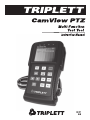
• Thank you for purchasing the Triplett CamView PTZ CCTV Monitor with
PTZ Controller. Please read the complete manual carefully before using
the product.
• To assure safe use of this product, please read the section on Safety
carefully, and observe any Cautions or Warnings posted there and
throughout this manual.
• Please keep this manual for future reference.
Page 1
Table of Contents
Safety Information ...............................................................................................1
Introduction .........................................................................................................2
Features and Function .......................................................................................2.1
Included Items ..................................................................................................2.2
Controls and Indicators .....................................................................................2.3
Connecting and Charging the Battery ................................................................2.4
Using the Camview ..............................................................................................3
General Instructions ..........................................................................................3.1
Introduction to Menu and Functions .................................................................3.2
Video Monitor Mode / PTZ Controller Parameter Setting ..................................3.3
Setting PTZ Parameters (Overview) ................................................................3.3.1
Setting PTZ Parameters (Detail) .....................................................................3.3.2
Using Presets .................................................................................................3.3.3
Accessing a PTZ Camera Menu ......................................................................3.3.4
Video Setting .....................................................................................................3.4
Color Bar Generator ...........................................................................................3.5
Cable Testing .....................................................................................................3.6
Capturing PTZ Protocol .....................................................................................3.7
Device Setting (User Settings) ..........................................................................3.8
Auto Power Off ...............................................................................................3.8.1
Prompt Sound ................................................................................................3.8.2
Language ........................................................................................................3.8.3
Brightness ......................................................................................................3.8.4
Specifications .......................................................................................................4
Page 2
1 Safety Information
• Use this product in accordance with any prevailing safety rules that
may be imposed by local or federal authorized bodies.
• Do not use this product if it is wet or in conditions where the
humidity exceeds 95%.
• Avoid exposing the product to dusty environments. Do not allow the
product to get wet, and do not immerse it in liquid of any kind.
• During transportation and use, avoid mechanical shock and vibration.
• For greatest safety, do not leave the product unattended while charging.
• Although the product contains automatic circuitry to prevent
overcharging, the battery life (number of charge / discharge cycles)
of the product can be maximized by limiting charge time to 8 hours.
• The product should not be used in the presence of flammable gases.
• Do not disassemble. There are no user serviceable components inside.
• The product should not be used in the presence of strong
electromagnetic fields.
• Don’t touch the product with wet hands. Although the product itself
cannot shock the user, circuits connected to the product
(cameras, switches, controllers, chargers, etc.) may present a
shock hazard under some conditions.
• Do not use strong detergents or solvents to clean the product.
A cloth slightly dampened with water is suggested. If the dirt is
not easy to remove, a mild detergent may be used.
Page 3
2 Introduction
The Triplett CamView PTZ is a multi-function test tool designed to aid CCTV
and Security electronics installers and maintenance technicians. A color LCD
video monitor allows viewing of security camera images to verify their operation
and setup. The CamView’s keyboard allows control and setup of the camera’s
PTZ (Pan, Tilt, Zoom) functions (if so equipped) via a standard RS-485, RS-422,
or RS-232 interface. A Color Bar Generator provides a standard test signal to
check video cables, video recorders, and video monitors. LAN cable can also be
tested using the CamView’s built-in cable tester.
The rugged yet lightweight construction and ergonomic design maximizes
convenience and portability, and the 10 hour rechargeable Li-on battery delivers
extended runtime. Its multiple functions, simple operation via on-screen menus,
and reliable performance makes the CamView an efficient time saving test tool
that will enhance any professional tool kit.
Page 4
2.1 Features and Function
• Full Color 2.6” TFT-LCD Video Monitor
• OSD (On Screen Display) of all Modes, Functions, and Settings
• Adjustable LCD Brightness / Contrast / Color Saturation
• BNC connectors match professional CCTV equipment
• Full Loop Thru capability or simultaneous View / Gen mode
• Auto NTSC / PAL detection and video display
• PTZ Keyboard allows fast access to Pan, Tilt, Zoom, Focus, and Iris
• Keyboard allows adjustment of Groups, Tours, and Presets
• Supports more than 20 PTZ Protocols including Pelco, Samsung,
Panasonic, and Sony formats
• Supports RS-485, RS-422, and RS-232 PTZ interfaces.
Baud Rates from 150 to 19.2K
• Data Monitor mode verifies presence of PTZ signals
• PTZ Transmit / Receive LEDs
• Color Bar Generator produces NTSC and PAL video formats
• LAN Cable Test identifies Opens, Shorts, or Miswires
• Rechargeable Lithium Ion Polymer Battery provides 11 hour work time
• On screen battery life indicator and LED charging indicator
• Operates from battery or AC power pak
• Auto-Power-Off extends battery life (can be defeated)
• Carrying case with shoulder strap included
• Neck strap for CamView included
• BNC cable and RS-485 / RS-422 cable included
• Universal AC power pak and charger included
• LAN Remote Terminator included
Page 5
2.2 Included Items
The following items are included with your Triplett CamView PTZ.
Remote Terminator for
LAN Cable Testing
(PN 79-809)
AC Power Pak
(PN 13848)
PTZ Test Cable
(PN 79-810)
BNC to BNC Patch Cable
(PN 79-811)
Page 6
2.2 Included Items Cont.
Shoulder Strap for Carrying Case
(PN 3206-94)
Carrying Case
(PN 10-4303)
Neck Strap for CamView
(PN 3206-95)
Instruction Manual
(PN 84-887)
Page 7
2.3 Controls and Indicators
Page 8
2.3 Controls and Indicators
1
AC Power Indicator. Lights when CamView
is operating from AC power.
2
Receive Indicator: Lights when PTZ signals are
being Received.
3
Transmit Indicator: Lights when PTZ signals are
being Transmitted.
4
Charge indicator: Lights while battery is charging.
Turns off when battery is fully charged.
5
Battery Life Indicator: Shows remaining battery charge.
When charging, indicates “FULL” when completely charged.
6
LCD Screen: Shows video images and On Screen
Display functions.
7
Menu: Shows available Functions, Settings,
Modes, etc.
8
POWER Button: Press for 2 seconds to turn power on or off.
A short press Hides or Reveals the PTZ controller menu.
9
MODE Button: Press momentarily to select one of the 6
available test or setting options from a drop-down menu.
10
SET Button : Press momentarily to enter a test or setting
mode, or press to enter a new value for a test or setting
parameter.
Page 9
2.3 Controls and Indicators
11
UP Button : Tilt the controlled camera ‘up’.
Navigate upward on a menu. Change a parameter value.
12
LEFT Button : Pan the controlled camera ‘left’.
Navigate left on a menu. Change a parameter value.
13
RIGHT Button : Pan the controlled camera ‘right’.
Navigate right on a menu. Change a parameter value.
14
DOWN Button : Tilt the controlled camera ‘down’.
Navigate downward on a menu. Change a parameter value.
15
ENTER/OPEN Button : Confirm the value or setting of
various parameters. OPEN the camera aperture (iris).
16
RETURN/CLOSE Button : ‘Return’ or ‘cancel’ while setting parameters. CLOSE the camera aperture (iris).
17
NEAR Button: Adjust Focus for nearer objects.
18
FAR Button: Adjust Focus for farther objects.
19
TELE Button: ‘Zoom In’ on an object or scene.
20
WIDE Button: ‘Zoom Out’ from an object or scene.
Page 10
2.3 Controls and Indicators
22
Press to Reset CamView to factory defaults.
23
External power jack (5V, 2A): Use only the provided power adapter.
24
UTP Cable Test jack (RJ-45): Use to test cables with RJ-45 plugs.
25
RS232 Jack: Use for connection to PTZ cameras requiring an
RS-232 control signal.
26
Video input (BNC): Input for NTSC or PAL video signal from
camera or other video device
27
Video output (BNC): Loopthrough from Video input (26) or
NTSC / PAL Color Bar video output
28
RS485/422 Connector: PTZ control signal input/output.
Connect to camera or other PTZ device.
29
Attachment point for neckstrap.
Page 11
2.4 Connecting and Charging the Battery
The CamView is shipped with the battery disconnected to prevent any battery
drain that may reduce the battery life. Prior to the use of the instrument, the battery wires inside the battery compartment must be connected together. Open the
battery compartment. Observing the proper polarity (red wire to red wire, black
wire to black wire), connect the battery wires and replace
the cover on the battery compartment.
There is no need to unplug the battery if the CamView is being used regularly
(at least once every few weeks). If the CamView will be unused for more than 1
month, unplug the battery for storage.
For first time usage, it is recommended that the battery be ‘conditioned’ by
operating the CamView until it turns itself off. This will provide the best battery
life in the coming months. If the Auto Power Off feature is activated, it may be
necessary Disable it to allow the product to run until the battery is depleted.
Page 12
2.4 Connecting and Charging the Battery Cont.
To turn the unit on, press POWER for about 2 seconds and release when the
unit powers up. After depleting the battery, connect the supplied battery charger
to the power jack (23). The red Charge Indicator
should turn on. Charge
the battery until the indicator turns off. This could take 4 to 5 hours. When the
Charge Indicator
turns off, the battery is approximately 90% charged.
The charging time can be extended for about 1 hour to ‘top off’ the battery
charge. To obtain the best battery life, limit charging time to about 8 hours.
Leaving the battery on continuous charge may reduce the battery life.
• The CamView can be used while its batteries are being charged, however,
the charging time will be increased.
If the CamView behaves abnormally, it can be reset to the
factory default settings by pressing the RESET button (22).
Page 13
3 Using the CamView
3.1 General Instructions
To turn the unit on, press
powers up.
POWER
for about 2 seconds and release when the unit
To turn the unit off, press POWER for about 2 seconds and release when the unit
powers down. The unit will remember its Mode setting, and when next turned on,
will be in this Mode.
After the CamView is powered on, it will be in the Mode that it was in when last
power off. To see a list of the different modes, press and release the MODE button. The Mode Menu will display for a few seconds. While the Mode Menu is
displayed, select a different Mode by pressing the MODE button repeatedly until
the desired Mode is highlighted on the Menu. You may also select a different
Mode by pressing the
or
buttons when the Mode Menu is displayed.
Once a Mode is selected, the
or the SET buttons may
be used to change settings and alter parameters. If the PTZ Mode is selected,
RETURN
ENTER
NEAR
FAR
WIDE
TELE
the
buttons directly conCLOSE
OPEN
trol the motion and settings of the camera. Notice that the
indicator lights
when any of these buttons are pressed in the PTZ mode. This shows that PTZ
control signals are being generated at the PTZ Connector (28).
When in the PTZ mode, the video input signal can be displayed in full-screen
mode by pressing and releasing the POWER button. To reveal the PTZ header bar
and battery indicator, press and release the POWER button again.
Page 14
3 Using the CamView Cont.
Use the following diagram as a guide to connect the CamView to a PTZ camera.
Connect the video output of the camera to the Video Input of the CamView.
The Video Output of the CamView may be connected to the video input of another video monitor (such as the monitor in the video closet or the monitor at the
guard station). The CamView usually operates in ‘Loopthrough” mode, passing
the Video Input signal to the Video Output connector.
Connect the PTZ control signal from the CamView RS485 or RS232 connector
to the mating connector on the PTZ camera. Observe the proper polarity (D +/ A
to D+ or A, D -/ B to D- or B).
Caution: Do not connect the CamView PTZ connector to anything other than a
camera’s PTZ connections. To do otherwise may damage the CamView.
Page 15
3.2 Introduction to Menu & Functions
Pressing the MODE button reveals the
main menu. By repeatedly pressing the
MODE
button, the user can select any of
the CamView’s test functions or modes,
such as: ‘PTZ controller’, ‘Video setting’,
‘Colorbar generator’, ‘Cable tester’, ‘Data
monitor’, or ‘Device setting’.
1. PTZ Controller (and Video Monitor)
This mode is typically used to display
video images and to control or set
parameters on a PTZ camera. A video
signal connected to the CamViews
Video Input will appear on the PTZ
controller screen. If no video signal is
applied, the screen will display “
No video input”. Basic PTZ camera
functions (left, right, up, down, etc.)
can be controlled by pressing the CamView’s buttons. To access PTZ communication parameters, speed adjustments, and presets, press the SET button.
When in the PTZ mode, the video input signal can be displayed in full-screen
mode by pressing and releasing the POWER button. To reveal the PTZ header bar
and battery indicator, press and release the POWER button again.
Page 16
3.2 Introduction to Menu & Functions Cont.
2. Video setting
This mode is used to adjust the CamView’s LCD Brightness, Contrast, and
Color Saturation. If a video signal is applied to the Video Input connector,
the video image will appear on this
screen. If a video signal is not present,
the screen will display “No video input”.
3. Colorbar generator
The CamView contains a built-in Colorbar
generator. Seven standard PAL and
NTSC formats are selectable by using
the
and
buttons.
The LCD screen can be selected to display the Colorbar signal or a video signal
applied to the CamView’s Video Input.
4. Cable tester
The CamView can test cables consisting
of 2 to 8 wires. The ends of the cable must
be terminated in RJ-45 plugs to match the
jacks on the CamView and the Remote
Terminator. Ethernet LAN cables are
commonly terminated in RJ-45 connectors.
The screen to the right shows the test
results of a cable with ‘cross’ wires and an
open wire on pin 8. The Remote is number 255 (This is the standard Remote
provided with the CamView).
Page 17
3.3 Video Monitor Mode/ PTZ Controller Parameter Setting
5. Data Monitor
The CamView will display incoming PTZ
signals. This allows the user to verify that
the PTZ control wires have a PTZ signal
present. This is useful to determine if a
non-responsive PTZ camera is actually
receiving a PTZ control signal.
6. Device setting (User Settings)
Auto poweroff: Disable or set time for
auto power off.
Prompt sound: Turn ‘keybeep’ on or off.
Language: Select English or Chinese.
Brightness: Set menu brightness
from 0 to 7.
3.3 Video Monitor Mode (PTZ controller)
Press MODE to select ‘PTZ controller’. The
screen displays ‘No video input’ when a
video signal is not applied to the CamView’s
Video Input connection. If a video signal is
applied, it will appear on the LCD screen.
Page 18
3.3 Video Monitor Mode/ PTZ Controller Parameter Setting Cont.
3.3.1
Setting PTZ Parameters
(Overview)
In the PTZ controller mode, press SET
to access settings for the PTZ parameters. Press
or
to move the
yellow cursor, selecting the desired
parameter. Press
or
to change
the value of the parameter.
After setting the value of the
parameter(s), press SET to save the
value(s) and exit.
RETURN
Press CLOSE to exit without saving.
A. Protocol
Move the cursor to “Protocol” and select the protocol used by the camera that
will be controlled. See Specifications for a list of the available protocols.
B. Port
Move the cursor to “Port”. Select the port on the CamView that will be used to
communicate with the camera. RS485 and RS232 ports are available.
C. Baud
Move the cursor to “Baud”. Select the same baud rate that the camera is set
to. Baud rates available for selection: 150, 300, 600, 1200, 2400, 4800, 9600,
19200.
D. Address
Move the cursor to “Address”. Set the value to the address of the camera to be
controlled.
Page 19
3.3 Video Monitor Mode/ PTZ Controller Parameter Setting Cont.
E. Pan speed
Move the cursor to “Pan speed”. Select a value for the Pan
speed from 0 to 63.
Note: The range of adjustment can change depending on the
camera.
F. TiltSpeed
Move the cursor to “TiltSpeed”. Select a value for the Tilt speed
from 0 to 63.
Note: The range of adjustment can change depending on the
camera.
G. Set ps (Setup Preset)
Move the cursor to “Set ps”. Choose a number from 0 to 127 to
identify the preset location.
H. Get ps (Go to Preset)
Move the cursor to “Get ps”. Select a preset number that will be
activated.
Page 20
3.3.2 Setting PTZ Parameters (Details)
Camera Information
Detailed information about a PTZ camera must be known in order to set it up
or test it. First, the PTZ protocol that the camera is set to must be known. Some
cameras offer multiple protocols, and some manufacturers use the same protocol for all of their cameras. ‘Pelco D’ is a popular protocol used by many cameras
and installers.
Most camera settings are determined by the installer. So a record must be
kept of the settings, or the camera must be examined to determine the settings.
Cameras often use a combination of Hardware and Software settings. Hardware
settings are often set with DIP switches located in the base of the camera. Software settings can only be accessed after the camera is powered up and communicating with its controller.
The Baud Rate must be known. This is often determined by a DIP switch setting on the camera. If the CamView and the camera are not set to the same Baud
Rate, they will not communicate.
The camera Address must be known. This is often determined by a DIP switch
setting on the camera. If the CamView and the camera are not set to the same
Address, they will not communicate.
The type of interface must be known. Most new cameras use RS-485. The
CamView supports RS-232, RS-485, and RS-422 Simplex. The CamView has 2
port connections. The RS-232 interface is through a separate port on the side
of the CamView. The RS-485 and RS-422 Simplex interface is on the top of the
CamView. They share the same connector. When configuring the CamView to
communicate with a PTZ camera, select the proper Port and connector (RS-232
or RS-485).
Page 21
3.3.2 Setting PTZ Parameters (Details) Cont.
A. Connecting the CamView to an RS-485 PTZ Camera:
Connect the video signal from the PTZ camera to the VIDEO IN jack of the
CamView. This is usually accomplished with a coaxial cable with BNC connectors. Sometimes, the camera uses a different connection (because BNC’s are
too large). Connect the PTZ wires from the camera to the RS-485 jack of the
CamView using the provided PTZ test cable.
B. Setting the Communication Port:
With the CamView in the ‘PTZ controller’ mode, press SET to access the PTZ
settings. Then press
or
to move the cursor to “Port”, and select
‘RS485’ by pressing
or
as required. Press ENTER
to save the setting.
OPEN
RETURN
Press CLOSE to exit.
C. Setting the Address
With the CamView in the ‘PTZ controller’ mode, press SET to access the PTZ
settings. Then press
or
to move the cursor to “Address”, and set
the address to match the camera address by pressing
or
as required.
Press ENTER
to save the setting. Press RETURN
to exit.
OPEN
CLOSE
D. Setting the Protocol
With the CamView in the ‘PTZ controller’ mode, press SET to access the PTZ
settings. Then press
or
to move the cursor to “Protocol”, and select
ENTER
the camera’s PTZ protocol by pressing
or
as required. Press OPEN to
RETURN
save the setting. Press CLOSE to exit.
E. Setting the Bit Rate
With the CamView in the ‘PTZ controller’ mode, press SET to access the PTZ
settings. Then press
or
to move the cursor to “Baud”, and set the
baud rate to match the camera by pressing
or
as required. Press ENTER
OPEN
RETURN
to save the setting. Press CLOSE to exit.
Page 22
3.3.2 Setting PTZ Parameters (Details) Cont.
F. Testing PTZ communication
If the PTZ setup is correct, and the camera is operating properly, it should
respond to the buttons on the CamView keyboard. Set the CamView to the ‘PTZ
controller’ mode. The video image from the camera should be visible on the LCD
screen. Press the buttons on the keyboard to verify that the camera responds to
the CamView’s commands.
Some cameras may not respond to the Aperture or Focus settings because these
are automatically set by the camera. There may be a software setting in the
camera menu that allows the camera to respond to manual Aperture and Focus
commands. To allow manual operation of these settings, the camera menu must
be accessed and the appropriate settings altered.
Page 23
3.3.2 Setting PTZ Parameters (Details) Cont.
3.3.3 Using Presets
Presets’ are ‘pointing locations’ stored in the camera. The camera may be
pointed at any object within its field of view, zoomed in, and focused. By assigning a ‘preset’ to this location, the camera remembers this specific setup and can
go to it on command.
To setup a preset:
While in the ‘PTZ controller’ mode, use the CamView keyboard to point the camera to the desired location, zoom in, and set the focus and aperture. Press
SET
to access the PTZ parameters, then use
and
to move the cursor to “Set ps”. Chose a preset number (the number chosen must agree with
available memory in the camera)… for example ‘10’. Use
and
to set
ENTER
RETURN
the value to ‘10’. Press OPEN to save the setting. Press CLOSE to exit. If preset
‘10’ already exists, it will be overwritten with the new location. It is common for
cameras to have from 20 to over 100 user settable presets.
To activate a preset:
While in the ‘PTZ controller’ mode, press SET to access the PTZ parameters,
then use
and
to move the cursor to “Get ps”. Select a preset number
ENTER
by using
and
. Press OPEN to activate the preset. The CamView will exit
the ‘Set’ mode and return to the ‘PTZ controller’ screen, where the image of the
preset location chosen will appear.
Page 24
3.3.4 Accessing a PTZ Camera Menu
PTZ cameras have many functions that can be accessed from their main menu.
When the menu is accessed, the camera inserts the menu information in the outgoing video signal. This allows the user to see the menu on a video monitor (like
the CamView) attached to the camera. If the camera overlays the menu with the
camera image, it may be difficult to see some of the menu settings. In this case
it is advisable to point the camera at a contrasting background before accessing
the menu.
It is beyond the scope of this manual to give instructions on how to set the
camera parameters. The method varies depending on the manufacturer and
the camera. It is up to the user to understand the camera and its settings. The
following is for illustration only. The main menu of the particular camera used
as an example is accessed by preset ‘064’. Other cameras use a different preset
number to access their main menu.
While in the ‘PTZ controller’ mode, press SET to access the PTZ parameters,
then use
and
to move the cursor to “Get ps”. Select ‘064’ by using
ENTER
and
. Press OPEN to activate the preset. The CamView screen should then
display the camera’s main menu.
Page 25
Camera Menu (For reference only)
MAIN MENU
1. DISPLAY SETUP
2. CAMERA SETUP
3. CONTROL SETUP
4. CAMERA MASK SET
5. PROGRAM
6. PAL CAMERA
7. CAM DEFAULT SET
8. DOME RESET
9. EXIT
The meaning and available settings of the menu items are determined by the
camera manufacturer. Please review the manufacturer’s camera information for
detailed instructions.
Auto Scan
Many PTZ cameras have an ‘Auto Scan” function. This function usually commands the camera to scan (pan) back and forth repeatedly over a preset location.
To access this function, the camera’s Auto Scan command number must be
known. For the camera in this example, the command is ‘098’. The camera may
have more than one Auto Scan routine that can be accessed by using the appropriate command numbers.
Page 26
It is often possible to set the details of the Auto Scan in the camera menu. For
example, the endpoints for the left/right pan and the up/down tilt can usually
be set. To stop the Auto Scan, send the camera to any new command… like
momentarily press the
button.
Other presets available in the example camera
Preset 033 ……….. Auto-rotate 180 degrees (flip)
Preset 034 ……….. Reset Pan / Tilt to the origin (zero)
Preset 096 ……….. Tour 1
Preset 094 ….……. Day / Night mode
3.4. Video Setting
This mode is used to adjust the Brightness, Contrast, and Color Saturation
of the video image. If a video signal is
applied to the Video Input connector, the
video image will appear on this screen
and a message will indicate if the video
signal is PAL or NTSC format. If a video
signal is not present, the screen will
display “No video input”.
‘Brightness’ can be varied from -128 to +127. A typical setting is +0.
‘Contrast’ can be varied from -128 to +127. A typical setting is +40.
‘Saturation’ can be varied from -128 to +127. A typical setting is +40.
Use the MODE button to select the ‘Video Setting’ mode. Adjust the video settings
using the
and
buttons to select the desired parameter and
set its value.
Page 27
3.5. ColorBar Generator
The ‘Colorbar generator’ can generate
a colorbar signal in 7 different video
formats. Select the format appropriate for
the video equipment to be tested. In the
USA, the common format is NTSC-M
(RS170A). The colorbar video signal can
be used to test the connection between
a camera and a monitor or other video
equipment. By connecting the CamView
to the video cable at the camera, and generating a colorbar signal, the colorbar image should appear on the monitor at the far end of the cable. Failure to
appear on the monitor, with good color, brightness, and contrast, indicates a
problem with the interconnecting cable or the monitor itself. The colorbar can
also be used as a test signal for a video recorder…… verifying that video can be
recorded and played back with acceptable quality.
In the ‘Colorbar generator’ mode, the LCD screen can be selected to display
the Colorbar signal or a video signal applied to the CamView’s Video Input.
• Use the MODE button to select the ‘Colorbar generator’ mode.
• Use
and
to select the desired video format. NTSC-M (RS170A) is
usually used in the USA. The Colorbar image will display on the LCD.
• If the user prefers to see the image from the Video input, use
and
to select the ‘LCD’ setting, then use
and
to select ‘Video output’ (Colorbar) or ‘Video input’ (signal applied to the CamView’s Video input). If a video
signal is not present at the Video input, the LCD will display ‘No video input’.
When the LCD is selected to ‘Video input’, the CamView continues to output
the Colorbar signal from its Video Out connector.
Page 28
3.6 Cable Testing
The CamView can test cables consisting of 2 to 8 wires. The ends of the cable
must be terminated in RJ-45 plugs to match the jacks on the CamView and the
Remote Terminator. Ethernet LAN cables are commonly terminated in RJ-45
connectors.
Use the MODE button to select ‘Cable tester’.Connect one end of the cable to be
tested to the RJ-45 connector on the side of the CamView. Connect the other end
of the same cable to the Remote Terminator. View the test results on the ‘Cable
tester’ screen.
A good ‘straight-through’ LAN cable
will test as shown. The straight-through
cable is identified as a ‘Pin to Pin’ cable
connected to Remote 255.
Page 29
A standard LAN ‘crossover cable’ will
display like this:
Shorted or Open wires are indicated by
a red ‘X’ on the screen. The cable in the
following example is miswired and has
Opens or Shorts on wires 1, 2, and 8.
3.7. Capturing PTZ protocol
The CamView can view PTZ codes using
its ‘Data monitor’ mode. This allows the
user to verify that the PTZ control wires
have a PTZ signal present. This is useful to
determine if a non-responsive PTZ camera
is actually receiving a PTZ control signal.
The actual codes are generally meaningless
to the average user. There is little chance of
decoding their meaning without in-depth knowledge of the PTZ coding scheme.
What’s important is that the PTZ codes are present in the PTZ control wires
connected to a PTZ camera.
Page 30
Use the MODE button to select ‘Data monitor’. The ‘Data monitor’ screen will
appear, showing the current Port and Baud settings. If these do not agree with
the Port on the CamView being used for the test, or the Baud Rate of the PTZ
signal, the settings must be altered so that they do agree. If the settings are OK,
observing the proper polarity, connect the CamView’s PTZ connector to the wires
to be tested. If PTZ signals are present, a display similar to that shown will appear. The display may update periodically and the values may change. If no PTZ
data appears on the LCD, reverse the polarity of the PTZ connection. If data then
appears, note the polarity of the PTZ wires. They must be connected to the PTZ
camera in the correct polarity, or the camera may not respond to PTZ signals.
If the CamView’s ‘Port’ or ‘Baud’ needs to be changed, press SET to access
these settings. ‘Port’ will be accessed first. Use the
and
buttons to
select the correct port. To save the setting and move on to changing the ‘Baud’,
press SET again, then use the
and
buttons to select the correct baud
rate. To save the setting press SET .
3.8. Device setting (User Settings)
Use the MODE button to select ‘Device
setting’. To change any of the settings,
use
or
to move the cursor to
the desired item, then alter its value using
the
or
buttons.
The new values must be saved in order
to take effect. If you alter any values, a
message will appear at the bottom of the
ENTER
screen reminding you to press OPEN to
apply the changes. Or the changes may
be canceled by pressing the RETURN
CLOSE button.
Page 31
3.81 Auto poweroff
The user may set a length of time, in 5 minute increments up to 60 minutes,
during which the CamView will operate normally, but after which the product
will turn itself off. If any button on the CamView is pressed, the ‘time-out’ is reset.
This feature is intended to preserve the charge on the battery if the product is
unused for some period of time. The ‘Auto poweroff’ feature can be Disabled if
desired.
Use
or
to move the cursor to ‘Auto poweroff’. Then use
or
to select the desired ‘time-out’ interval. Select ‘Disabled’ to allow the CamView to
run continuously. ‘Apply’ the change by pressing ENTER
OPEN .
3.8.2 Prompt sound
The ‘Key Beep’ can be turned on or off.
Use
or
to move the cursor to ‘Prompt sound’. Then select ‘Off’ or ‘On’
using the
or
buttons. ‘Apply’ the change by pressing ENTER
.
OPEN
3.8.3 Language
English or Chinese can be selected as the operational language for the
CamView. Use
or
to move the cursor to ‘Language’. Then select
‘English’ or ‘Chinese Symbols’ using the
and
buttons. ‘Apply’ the
change by pressing ENTER
.
OPEN
3.8.4 Brightness
The brightness of the menus can be set as desired.
Use
or
to move the cursor to ‘Brightness’. Then select a brightness
ENTER
from 0 to 7 using the
and
buttons. ‘Apply’ the change by pressing OPEN .
Page 32
4. Specifications
Video Monitor
Formats Supported
Display
Display Adjustments
Connections
NTSC and PAL (Auto Selected)
2.6 inch TFT-LCD ,960 x 240 resolution
Brightness, Contrast, Saturation (Color Level)
1 BNC Video Input, 1 BNC Video Output
(Loopthrough)
1.0 Vp-p into 75 Ohms
Video Input Level
PTZ controller
Communication
RS232, RS422 simplex and RS485
PTZ Protocols Supported Pelco D, Pelco P, YAAN, YAAN-O, Samsung,
Panasonic, Lilin-FAST, Lilin-MLP2, Molynx,
Minking A01, AD, Fastrax, CBC, LC-NEW,
WV-CS850, SONY-EVI, LG-MULTIX, Da Hua, PEARMAIN, Minking B01, ALEC
Address Range 0 to 254
Baud Rates
150,300,600,1200,2400,4800,9600,19200bps
Connections
RS232: 15 pin D-sub
RS422 and RS485: Alligator clips on provided
adaptor cable
Colorbar Generator
Pattern
8 vertical color bars. White, Yellow, Azure, Green,
Magenta, Red, Blue, Black.
Formats Supported
PAL-B,D,G,H,I; PAL-M; PAL-N (Arg.); PAL-N
(non Arg.); NTSC-M (CCIR601); NTSC-M (Japan);
NTSC-M (RS170A)
Connection
1 BNC Video Output
Video Signal
1.0 Vp-p into 75 Ohms
Page 33
4. Specifications Cont.
RJ-45 CABLE TEST
Tests Performed
Connections
Tests 2 to 8 conductors for Opens, Shorts,
and Miswires.
Female RJ-45 on CamView, Female RJ-45
on Remote. Tested cable must have male
RJ-45 connectors on both ends.
Pin to pin connections displayed,
Opens and Shorts indicated with a red ‘X’.
Indications
PTZ data Capture and display
Test Performed
Captures and displays PTZ data from
sending device.
Connections
RS232: 9 pin D-sub (DB9)
RS422 and RS485: Alligator clips on
provided adaptor cable
Settings
Port selection and Baud rate
POWER
AC Adaptor/Charger
Input: 100 to 240VAC, 50/60Hz, 0.30A,
American Blade
Output: DC5V / 2A, 5.5mm x 2.1mm coaxial,
center positive
Battery
Built-in 3.7V Lithium polymer battery, 2000mAh
Charging Time
Approximately 4 hours for 90% charge (the Charge
indicator LED turns off). Additional 1 hour for full
charge. Limit charging time to 8 hours for best
battery life.
Operating time on full
battery charge
Approximately 11 hours
Auto Poweroff
Selectable in 5 minute increments from 5 min to
60 min. Can be disabled.
Page 34
4. Specifications Cont.
Environmental
Working Temperature
Working Humidity
Physical
Dimensions
Weight
Certifications
-30F to 160F
0%-90% RH
2” x 4” x 6”
10oz (CamView only)
CE and FCC
Triplett Product Return Instructions
In the unlikely event that you must return your Triplett equipment for repair, the
following steps must be taken.
1) Call 1-800-TRIPLETT to obtain a Return Material Authorization (RMA)
number from Customer Service.
2) Enclose a copy of the original sales receipt showing date of purchase.
3) Clearly print the RMA number on the outside of the shipping container.
4) Return to:
Triplett / Jewell Instruments
850 Perimeter Road
Manchester, NH 03103
ATTN: Repair Dept.
Page 35
Triplett One Year Limited Warranty
Triplett warrants instruments and test equipment manufactured by it to be free
from defective material or workmanship and agrees to repair or replace such
products which, under normal use and service, disclose the defect to be the
fault of our manufacturing, with no charge within one year of the date of original
purchase for parts and labor. If we are unable to repair or replace the product,
we will make a refund of the purchase price. Consult the Instruction Manual
for instructions regarding the proper use and servicing of instruments and test
equipment. Our obligation under this warranty is limited to repairing, replacing,
or making refund on any instrument or test equipment which proves to be defective within one year from the date of original purchase.
This warranty does not apply to any of our products which have been repaired or
altered by unauthorized persons in any way so as, in our sole judgment, to injure
their stability or reliability, or which have been subject to misuse, abuse, misapplication, negligence, accident or which have had the serial numbers altered,
defaced, or removed. Accessories, including batteries and fuses, not of our
manufacture used with this product are not covered by this warranty.
To register a claim under the provisions of this warranty, contact Triplett’s Customer Service Department for a Return Authorization Number (RMA) and return
instructions. No returned product will be accepted without an RMA number.
Upon our inspection of the product, we will advise you as to the disposition of
your claim.
ALL WARRANTIES IMPLIED BY LAW ARE HEREBY LIMITED TO A PERIOD OF
ONE YEAR FROM DATE OF PURCHASE, AND THE PROVISIONS OF THE WARRANTY ARE EXPRESSLY IN LIEU OF ANY OTHER WARRANTIES EXPRESSED
OR IMPLIED.
Page 36
Triplett One Year Limited Warranty Cont.
The purchaser agrees to assume all liability for any damages and bodily injury
which may result from the use or misuse of the product by the purchaser,
his employees, or others, and the remedies provided for in this warranty are
expressly in lieu of any other liability Triplett may have, including incidental or
consequential damages.
Some states (USA ONLY) do not allow the exclusion or limitation of incidental
or consequential damages, so the above limitation or exclusion may not apply
to you. No representative of Triplett / Jewell Instruments or any other person
is authorized to extend the liability of Triplett in connection with the sale of its
products beyond the terms hereof.
Triplett reserves the right to discontinue models at any time, or change specifications, price or design, without notice and without incurring any obligation.
This warranty gives you specific legal rights, and you may have other rights
which vary from state to state.
Page 37