1
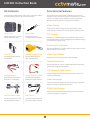
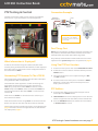
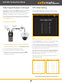
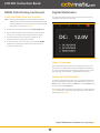
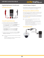
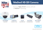
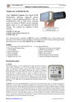
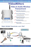
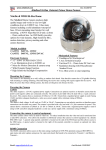
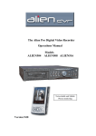
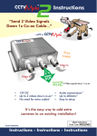
PTZ Control Testing RS485 Data Test Function Monitor Output Testing Built-in Multimeter Video Signal Meter Network Cable Tester LCD330 Up To 10 Hour Battery Life Essential CCTV Camera Test Monitor The feature packed LCD330 CCTV test monitor kit comes with voltage probes for use with the built-in multimeter, an RS485 data test cable, a 12V DC power cable so that cameras can be powered by the test monitor during configuration, a short BNC cable for connecting test monitor to cameras or monitors, sturdy nylon carry case with optional shoulder strap, neck strap, PSU for charging the LCD330 and a network cable tester. LCD330 Instruction Book LCD330 Instruction Book Safety Information Contents Precautions Before Using The LCD330 Safety Information 2 1. Read and understand the User Manual before using this product. Getting Started 3 2. Ensure the CCTV test monitor is used within each specified range to avoid damaging the unit. Connections & Controls 3 3. The LCD330 should only be used under the following conditions: Kit Contents 5 Functions & Features 5 Battery & Power 6 Main Menu 6 Precautions When Using The LCD330 System Information 7 1. Do not use the test monitor in damp, humid or leaking gas environments. Video Testing 8 PTZ Testing & Control 9 Video Signal Analysis 10 UTP (Network) Cable Testing 11 Video Generator 12 RS485 Data Testing 13 Digital Multimeter 14 12V DC Power Output 15 Specification & Warranty 16 A.Temperature: -30° ~ 70° B. Relative humidity: 30% ~ 90% C. Recharging voltage: 9V DC 2.0A 2. Do not touch the LCD330 with moist or wet hands. 3. Measurements may be incorrect when the CCTV test monitor is used in places subjected to strong magnetic fields or electromagnetic waves. 4. Be careful not to expose the ports or joints to dirt or liquid. 5. Do not disassemble the CCTV test monitor. If the unit requires any repairs return the unit to the retail outlet you purchased it from. Attempting to repair the unit yourself will void the warranty. 6. Do not connect this unit to other Input/Output devices when using the multimeter function. Precautions When Charging The Battery 1. Only ever use the original battery supplied with the test monitor, when charging the battery you should only use the original power adapter provided. 2. Do not short-circuit or disassemble the battery. 3. Do not use the multimeter function when charging the battery. 2 LCD330 Instruction Book Getting Started Before taking the CCTVmate out on its first job, please ensure that the unit is fully charged by using the charger supplied. For more information on charging the device see the ‘Battery & Power’ section on page 6. Connections & Controls Front Receiving Indicator Transmitting Indicator Flashes when data is being received. Flashes when data is being transmitted. Charging Indicator Power Indicator Solid light when charging, flashing when fully charged. Solid light when the test monitor is on. 3” LCD Screen Open Iris & Select 960 x 240 Resolution. Open Iris in PTZ control mode or ‘Confirm’ current selection or input. Close Iris & Exit Close Iris in PTZ control mode or ‘Cancel’ current selection or input. Menu Long press returns to main menu. Quick press displays and hides sub menu. Tele 0-9 Zoom in PTZ or start video test signal. Input menu or preset number. Direction Buttons Wide Move PTZ and select menu options. Zoom out PTZ or close video test signal. Address Far Input the address of the PTZ you wish to control. Adjusts PTZ to focus on far away objects. Set Preset Set preset in PTZ control mode. Call Preset Near Call preset in PTZ control mode. Adjusts PTZ to focus on near by objects. 3 LCD330 Instruction Book Side 1 Power On / Off Power Input UTP (RJ45) Socket Power switch. 9V DC jack input. UTP socket for network cable testing. Side 2 RS232 Port 12V DC Output Fold-out Stand For configuration and operation via RS232. For powering 12V DC cameras when testing. Optional fold-away stand. Top Bottom RS485 / RS422 Port + Probe Connection For testing, configuration and control. Connection for ‘Positive’ probe when using the multimeter. Video Input Video Output - Probe Connection BNC connection for video input from the camera. BNC connection for video output to monitor. Connection for ‘Ground’ probe when using the multimeter. 4 LCD330 Instruction Book Kit Contents Functions & Features The LCD330 is supplied with all the cables and tools needed for testing the key aspects of a CCTV installation. The LCD330 is one of the most comprehensive CCTV test monitors on the market. This feature packed device is a must have for any CCTV installer offering all the functions you would only expect to find on higher priced models. Video Testing Displays the camera’s image so that adjustments can be made during installation in order to get the prefect picture. Carry Case Neck Strap Sturdy nylon carry case with optional shoulder strap. For practicality and security whilst up a ladder. PTZ Control Functions as a standard keyboard to control the PTZ’s pan tilt and zoom functions as well as configuring the camera’s settings and creating or calling presets. Powering 12V Cameras The LCD330 features a 12V DC output so that cameras can be powered by the test monitor. 9V DC PSU Network Cable Tester Video Signal Meter For charging the LCD330 test monitor. Used to detect faults in UTP network cables. Displays peak and average video signal strength. Digital Multimeter The LCD330 can be used as a digital multimeter to measure AC and DC voltage and resistance. UTP Network Cable Tester Voltage Probes RS485 Data Test Cable Check straight and crossover cables for short circuits and incorrect terminations. Allows the test monitor to be used as a multimeter. For connecting RS485 & RS422 wires to the LCD330. Video Generator Creates a colour bar output for checking images and colours display correctly on composite monitors. RS485 Data Testing Displays data from PTZ control equipment so that settings can be analysed by an engineer. 12V DC Power Cable BNC Cable For powering cameras with the LCD330 test monitor. Used connect the LCD330 to camera, DVR or monitor. 5 LCD330 Instruction Book Battery & Power Main Menu Power Switch When the LCD330 is turned on the main menu will be displayed as shown below. The On/Off switch is located on the right hand side of the unit. See page 4. Auto Off After a period of inactivity the LCD330 will automatically turn off. To restart the device turn the power switch ‘Off’ and then back ‘On’ again. To see how to set the length of time before the device automatically turns off see page 7. Battery Life The LCD330 is fitted with a high capacity battery providing up to 10 hours of battery life off of a full charge. Charging Only charge the device with the 9V DC PSU supplied. The test monitor takes 6 hours to charge fully. The charging indicator will display a solid light when charging which will flash when the device is fully charged. As a safety feature the LCD330 will automatically stop drawing power when fully charged. Selecting Menu Item Checking Battery Level To select a menu item simply press they corresponding number on the keypad. To view the current battery level enter the ‘System Setup’ from the main menu (option 1). ‘Battery’ is the last item on the page and battery level is displayed in percent. The battery level will be displayed as 100 / 90 / 75 / 50 / 25 or 5%. It is recommended that you charge the LCD330 when the battery level drops to 25% to prevent the battery dying during an installation. Note: The firmware version and serial number can not be selected. Version & Serial Number The firmware version and serial number of the product are displayed at the bottom of the screen. Using The LCD330 When On Charge You can still use all the features of the LCD330 whilst it is on charge except the multimeter function. 6 LCD330 Instruction Book System Setup Idle Time In the System Setup menu you can view and configure system information and PTZ control settings. Set the period of time in minutes the device has to be inactive before automatically turning off. To disable automatic power off set the idle time to 000. 000 ~ 030 Battery Displays the current battery level. 100 / 90 / 75 / 50 / 25 / 5 How To Configure System Settings 1. At the main menu press ‘1’ to enter ‘SYSTEM SETUP’. 1. Press the ‘OPEN/SET’ to start setup. The first menu option will begin to flash on and off. 2. Press the ‘Up’ and ‘Down’ key to highlight the desired menu option. 3. Press the ‘Right’ arrow to switch to the parameter for selected menu item. 4. Press ‘Up’ or ‘Down’ to change the selected parameter. 5. Press ‘Left’ to save selection and return to menu item. Protocol 6. Press ‘Left’ again to finish setup. The menu items will stop flashing once setup is complete. Set the protocol of the LCD330 so that it matches that of the PTZ camera you wish to control. Available protocols: 7. To return to the main menu press and hold the ‘Menu’ button for 1 second. The device will beep twice and display the main menu. Pelco D / Pelco P / Samsung / MinKing / VIDO / Yaam / Molynx / CSR600 / Alec / Vicon / VideoTrec / AD 485 / DynaColor / MLP1 / MLP2 / KDT KB3 / KDT 405 / KDT 304 / LGM / EVERFOCUS / FASTRAX / SANYO SSP / VCL / ADT / ERNA / SIEMENS / HEIJMANS / VISCA / VIDEOTEC / U MACRO / HONEYWELL / TG. Com Set the communication port you wish to use. Available ports: 485 / 232 / 422 Rate (Baud Rate) Set the baud rate used by the LCD330 so that it matches that of the PTZ camera you wish to control. Available baud rates: 2400 / 4800 / 9600 / 19200 / 5100 Speed Set the speed at which PTZs pan and tilt when being controlled. 001 (Min) ~ 016 (Max) 7 LCD330 Instruction Book Video Testing Connection Example 12V DC Power Cable Supplied (Optional, Max 600mA) Video testing allows you to view the camera’s image during installation making it easier to position and configure the camera correctly. It can also be used to check the video signal at the camera end of the installation when fault finding. Video In Although primarily used for camera testing, other video sources such a distributors, quads and DVRs can be connected to the test monitor for testing video output. BNC To BNC Lead Supplied 12V DC 2.1mm Socket Camera Video Output DC 12V Output Using The Video Test Function 1. At the main menu press ‘2’ to enter ‘VIDEO AND PTZ TEST’. 2. To hide the camera’s address and video format press the ‘MENU’ button. 3. The screen brightness can be adjusted using the ‘BR+’ and ‘BR-’ buttons. 4. To return to the main menu press and hold the ‘MENU’ button for 1 second. The device will beep twice and display the main menu. What Information Is Displayed? As well as the camera’s image, the camera’s address (only used for PTZ testing) and video format are also displayed. If no video signal is received the screen will appear black and the video will read ‘NULL’. Connecting Cameras To The LCD330 To view a camera’s image on the test monitor use the short BNC lead provided to connect the camera’s video output to the LCD330’s video input. 12V DC cameras which draw 600mA or less can be powered by the LCD330 with the 2.1mm power cable supplied. For more information on powering cameras with the LCD330 see page 15. The locations of the LCD330’s connections are highlighted on page 4. All of the accessories supplied with the test monitor are displayed on page 5. 8 LCD330 Instruction Book PTZ Testing & Control Connection Example The PTZ test function allows you to control and configure PTZ cameras as you would with a standard keyboard. RS485 Test Cable Supplied PSU + - + Camera Video Output Video In The RS485 + must be connected to terminal ‘A’ on the LCD330. The RS485 - must be connected to terminal ‘B’. PTZ First Things First Before you can control or configure a PTZ you will need to set the protocol, communication method and baud rate of the LCD330 so that they match those of the target PTZ. The protocol, communication method and baud rate can be adjusted in the ‘System Setup’ menu as explained on page 7. What Information Is Displayed? Using The PTZ Test Function As well as the camera’s image, the address (ID) of the PTZ currently being controlled and video format are also displayed. If no video signal is received the screen will appear black and the video will read ‘NULL’. 1. At the main menu press ‘2’ to enter ‘VIDEO AND PTZ TEST’. 2. To hide the camera’s address and video format press the ‘MENU’ button. Connecting PTZ Cameras To The LCD330 3. The screen brightness can be adjusted using the ‘BR+’ and ‘BR-’ buttons. Connect the PTZ’s video output to the LCD330’s video input using the BNC to BNC lead provided. 4. To return to the main menu press and hold the ‘MENU’ button for 1 second. The device will beep twice and display the main menu. The RS485 test cable supplied is used for connecting the PTZ’s RS485 contacts to the test monitor. Connect the ‘Red’ spring clamp to the PTZ’s ‘RS485 +’ contact and the ‘Black’ clamp to the ‘RS485 -’. On the LCD330 the ‘RS485 +’ is connected to terminal ‘A’ and the ‘RS485 -’ is connected to terminal ‘B’. PTZ Address 2. To change the address to that of the PTZ you wish to control press the ‘ADDR’ button. PTZs which use RS422 are connected in the same way as those which use RS485. 3. ‘NEW ADDRESS’ will now be displayed on screen. Use the numeric keypad to enter the address of the desired PTZ. PTZs which communicate using RS232 are connected to the RS232 serial port on the left hand side of the test monitor. 4. Press the ‘OPEN/SET’ button to confirm the new address or ‘CLOSE/CLEAR’ to cancel. The locations of the LCD330’s connections are highlighted on page 4. All of the accessories supplied with the test monitor are displayed on page 5. PTZ Testing & Control continues on next page 9 LCD330 Instruction Book PTZ Testing & Control Continued Video Signal Analysis PTZ Control Video signal analysis allows you to check the strength of the video signal along the cable run in an attempt to find any possible faults. 1. To Pan and Tilt the PTZ simply use the ‘UP’, ‘DOWN’, ‘LEFT’, and ‘RIGHT’ arrow buttons. 2. To adjust the Iris use the ‘OPEN/SET’ button to open the iris and the ‘CLOSE/CLEAR’ button to close the iris. 3. To manually adjust the Focus, press the ‘FAR’ button to focus on objects in the distance and the ‘NEAR’ button to focus on objects close to the PTZ. 4. To adjust the Zoom press the ‘TELE’ button to zoom in and the ‘WIDE’ button to zoom out. Settings Presets 1. Position, focus and zoom the PTZ on the desired location as described on above. 2. Once the PTZ had been position press the ‘SET’ button. 3. ‘SAVE PRESET’ will now be displayed on screen. Use the numeric keypad to enter the preset number you wish to assign to the current position the current position. 4. Press the ‘OPEN/SET’ button to confirm the new preset or ‘CLOSE/CLEAR’ to cancel. What Information Is Displayed? Calling Presets When using the video signal analysis function the max peak to peak voltage of the video signal (MAX Vpp), the average peak to peak voltage (AVERAGE Vpp) and the sync signal will be displayed. 1. To recall a save preset press the ‘CALL’ button. 2. ‘CALL PRESET’ will now be displayed on screen. Use the numeric keypad to enter the preset number you wish to recall. Drops in the video or sync signal could result in no image at the DVR end of the cable run. By testing the video and signal strength at both the camera and DVR ends of the installation then comparing the results could highlight any possible faults. Differences in sync signals can be used calculate the impedance of the co-ax cable. 3. Press the ‘OPEN/SET’ button to confirm input or ‘CLOSE/CLEAR’ to cancel. Configuring PTZ Settings You are likely to encounter problems if the video peak to peak voltage drops below 0.7V or the sync signal drops below 0.3V. If no signal is being received ‘NO VIDEO’ will be displayed. 1. To configure the PTZ’s internal settings you will need to call the preset which displays the PTZ’s OSD. e.g. Call 95. 2. Use the arrow buttons to navigate the menu system and alter parameters. Connecting Cameras For Video Analysis 3. Press the ‘OPEN/SET’ button to confirm selection and the ‘CLOSE/CLEAR’ button to cancel or exit current menu. To achieve true readings the LCD330 must be connected in-line with a 75Ω load or a DVR on the cable. Exiting PTZ Test When checking the signal at the camera end, connect the camera to the ‘VIDEO IN’ socket using the short BNC lead provided. Connect the LCD330’s ‘VIDEO OUT’ socket to the start of the cable run with the DVR connected at the far end. 12V DC cameras which draw 600mA or less can be powered by the LCD330 with the 2.1mm power cable supplied. 1. To return to the main menu press and hold the ‘MENU’ button for 1 second. The device will beep twice and display the main menu. Video Signal Analysis continues on next page 10 LCD330 Instruction Book Video Signal Analysis Continued UTP Cable Testing For checking the signal at the DVR end, connect the LCD330’s ‘Video Out’ socket to the DVR with the short BNC lead provided. Connect the end of the cable run to the LCD330’s ‘Video In’ socket with the camera connected at the start. The UTP cable test function can be used to check straight and crossover network cables for shorts and open circuits. The locations of the LCD330’s connections are highlighted on page 4. All of the accessories supplied with the test monitor are displayed on page 5. Connection Example 75Ω Load Of DVR Video Out BNC To BNC Cable Video In PSU Camera Video Output What Information Is Displayed? The ‘UTP CABLE TEST’ screen shows the termination of each wire of the CAT5 at both ends of the network cable. Using The Video Signal Analysis Function The first column shows the 8 terminations in order from 1 to 8 in the end of the cable which is plugged into the LCD330. The second column shows the corresponding terminations at the opposite end of the network cable. 1. At the main menu press ‘2’ to enter ‘VIDEO AND PTZ TEST’. 2. Press ‘1’ to display the video signal analysis. If a termination in the second column displays a ‘0’ there may be an open circuit in that specific wire. If two terminations show ‘0’ they may both be open circuits or they could be short circuiting to each other 3. If you wish to refresh the results press ‘1’ again. 4. To return to the main menu press and hold the ‘MENU’ button for 1 second. The device will beep twice and display the main menu. The tables below show the correct terminations for both types of network cable. Straight (Patch) Cable Crossover Cable 1 ---------- 1 1 ---------- 3 2 ---------- 2 2 ---------- 6 3 ---------- 3 3 ---------- 1 4 ---------- 4 4 ---------- 4 5 ---------- 5 5 ---------- 5 6 ---------- 6 6 ---------- 2 7 ---------- 7 7 ---------- 7 8 ---------- 8 8 ---------- 8 UTP Cable Testing continues on next page 11 LCD330 Instruction Book UTP Cable Testing Continued Video Generator Connecting The Network Cable Tester The video generator creates a composite video output to test that monitors are displaying images and colours correctly. To preform a network cable test you will need the small Network Cable Tester supplied with the LCD330. Plug one end of the cable into the ‘UTP TEST’ port on the right hand side of the LCD330. Plug the other end of the network cable into the Network Cable Tester. The locations of the LCD330’s connections are highlighted on page 4. All of the accessories supplied with the test monitor are displayed on page 5. Connection Example LCD330 Network Cable Network Cable Tester (Supplied) What Is Displayed? The ‘VIDEO GENERATOR’ will create a colour bar made up of 7 different colours. Alternatively 1 chosen colour can be displayed full screen. Using The UTP Test Function 1. At the main menu press ‘3’ to enter ‘UTP CABLE TEST’. Connecting The LCD330 To A Monitor 2. Press the ‘OPEN/SET’ button to begin cable test. Simply connect the LCD330’s ‘VIDEO OUT’ socket to the monitors video input using the short BNC cable provided. If the monitor does not have a BNC input you will need to use a connector such as a BNC to Phono converter. 3. The test results will be displayed allowing you to diagnose any faults. 4. To return to the main menu press and hold the ‘MENU’ button for 1 second. The device will beep twice and display the main menu. The locations of the LCD330’s connections are highlighted on page 4. All of the accessories supplied with the test monitor are displayed on page 5. Video Generator continues on next page 12 LCD330 Instruction Book Video Generator Continued RS485 Data Testing Connection Example The RS485 data function allows you to check if PTZ control equipment is sending data and how it is configured. BNC To BNC Cable Video Out Composite Monitor Using The Video Generator Function 1. At the main menu press ‘4’ to enter ‘VIDEO GENERATOR’. 2. A colour bar will be displayed. To display a single colour full screen press the ‘OPEN/SET’ button. Repeatedly pressing the ‘OPEN/SET’ button will cycle through the 7 available colours and finally back to the colour bar What Is Displayed? 3. To display the generated video on the connected monitor press the ‘TELE’ button. When the video is displayed on the monitor the LCD330’s screen will be blank. The ‘RS485 DATA TEST’ displays hexadecimal data sent from the PTZ control device so that it can be analysed by an engineer. 4. To end the test on the connected monitor and return the image to the test monitor press the ‘WIDE’ button. Connecting A PTZ Controller To The LCD330 Connect the ‘RS485 +’ of the PTZ controller to terminal ‘A’ of the LCD330. The ‘RS485 -’ of the PTZ controller is then connected to terminal ‘B’. 5. To return to the main menu press and hold the ‘MENU’ button for 1 second. The device will beep twice and display the main menu. The locations of the LCD330’s connections are highlighted on page 4. Note: The Video Generator function is intended for testing composite monitors. Trying to display the video on anything else may result in the video signal not being recognised at all. Connection Example ‘RS485 -’ To ‘B’ ‘RS485 +’ To ‘A’ PTZ Control Equipment RS485 Data Testing continues on next page 13 LCD330 Instruction Book RS485 Data Testing Continued Digital Multimeter Using The RS485 Data Test Function The digital multimeter function can be used to measure DC voltage, AC voltage and resistance. Note: Before the RS485 data test will function correctly the baud rate of the LCD330 needs to match that of the PTZ control equipment. For instructions on setting the baud rate of the test monitor see page 7. 1. At the main menu press ‘5’ to enter ‘RS485 DATA TEST’. 2. On the PTZ controller send the command you wish to analyse. For example move the joystick to the right. 3. The hexadecimal values of the command will be displayed on the screen of the LCD330. 4. To return to the main menu press and hold the ‘MENU’ button for 1 second. The device will beep twice and display the main menu. What Is Displayed? DC and AC voltage measurements are displayed in volts and the resistance is measured in ohms. The digital multimeter has an auto range feature where the most appropriate unit is used depending on measurement. e.g. Millivolt (mV), Volt (V). Setting Up The Multimeter To use the multimeter function you will need to connect the two voltage probes supplied to the bottom of the unit. The ‘Red’ probe is connected to the ‘VΩ’ port and the ‘Black’ probe is connected to the ‘COM’ port. The locations of the LCD330’s connections are highlighted on page 4. All of the accessories supplied with the test monitor are displayed on page 5. Digital Multimeter continues on next page 14 LCD330 Instruction Book Digital Multimeter Continued 12V DC Power Output Connection Example The LCD330 has a useful 12V DC power output for powering 12V CCTV cameras and equipment. The LDC330 can provide 12V DC power up to a maximum current of 600mA. Powering Cameras With The LCD330 Connect the narrow end of the supplied 12V DC power cable to the ‘DC 12V OUTPUT’ of the LCD330. The standard 2.1mm DC plug is then connected to the CCTV camera. Red To VΩ The locations of the LCD330’s connections are highlighted on page 4. All of the accessories supplied with the test monitor are displayed on page 5. Black To COM Note: Only use LCD330’s power output to power 12V DC cameras and equipment. Using The Digital Multimeter Attempting to power devices which draw more than 600mA will automatically trigger the LCD330’s limiter and power output will be stopped. 1. At the main menu press ‘6’ to enter ‘Multimeter’. 2. Select the required test option by pressing the corresponding button. Press ‘1’ for ‘DC VOLTAGE’, press ‘2’ for ‘AC VOLTAGE’ or press ‘3’ for ‘RESISTANCE’. Do not connect the 12V DC output to the LCD330’s 9V DC input as this may damage the unit. Voltage tests are accurate to 0.1mV and the resistance test is accurate to 0.1Ωo. Connection Example The DC voltage test has a test range of 0-1000V. The AC voltage test has a test range of 0-750V. The Resistance test has a test range of 0-40MΩ. 12V DC Power Cable (Supplied) 3. To return to the main menu press and hold the ‘MENU’ button for 1 second. The device will beep twice and display the main menu. DC 12V Output Note: Do not use the multimeter function whilst the LCD330 is on charge. Do not test equipment outside the specified test ranges. Doing so may damage the LCD330. 15 LCD330 Instruction Book Specification Feature Video PTZ Multimeter Power & Battery Other Function Specification Video Input 1 Channel BNC Video Output 1 Channel BNC Format NTSC / PAL (Automatic) Display 3 Inch LCD Screen / 960 x 240 Resolution Protocol Pelco D / Pelco P / Samsung / MinKing / VIDO / Yaam / Molynx / CSR600 / Alec / Vicon / VideoTrec / AD 485 / DynaColor / MLP1 / MLP2 / KDT KB3 / KDT 405 / KDT 304 / LGM / EVERFOCUS / FASTRAX / SANYO SSP / VCL / ADT / ERNA / SIEMENS / HEIJMANS / VISCA / VIDEOTEC / U MACRO / HONEYWELL / TG Communication RS485 / RS422 / RS232 Baud Rate 2400 / 4800 / 5100 / 9600 / 19200 RS485 Input Terminal Strip RS422 Terminal Strip RS232 9 Pin RS232 Serial Port DC Voltage Test Range: 0 ~ 1000V / Accuracy: 0.1mV AC Voltage Test Range: 0 ~ 750V / Accuracy: 0.1mV Resistance test Range: 0 ~ 40MΩ / Accuracy: 0.1Ω Input Power 9V DC Battery 7.4V 1500mAh Rechargeable battery Recharge Time 6 Hours Battery Life 10 Hours Output Power 12V DC Max Current Output 600mA Output Power Battery Life 3 ~ 5 Hours OSD Language English Working Temperature -30oC ~ 70oC Working Humidity 30% ~ 90% Dimensions 166 x 91 x 48mm Weight 340g Warranty For service and support please contact the original supplier from which the LCD330 was purchased or visit www.cctvmate.com All specifications are approximate. We reserve the right to change any product specifications or features without notice. Whilst every effort is made to ensure that these instructions are complete and accurate, We cannot be held responsible in any way for any losses, no matter how they arise, from errors or omissions in these instructions, or the performance or non-performance of the equipment that these instructions refer to. WEE/CG0783SS This symbol on the products and/or accompanying documents means that used electronic equipment must not be mixed with general household waste. For treatment, recovery and recycling please return this unit to your trade supplier or local designated collection point as defined by your local council. © Copyright 2014 16