1
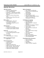
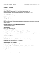
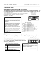
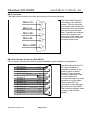
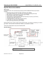
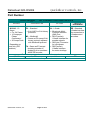
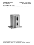
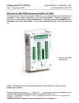
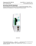
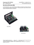
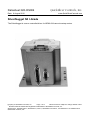
Datasheet:QCI-DS006 Date: 9 August 2010 QuickSilver Controls, Inc. www.QuickSilverControls.com SilverNugget N3 I-Grade The SilverNugget is a servo controller/driver for NEMA 34 frame microstep motors. Property of QuickSilver Controls, Inc. Page 1 of 11 This document is subject to change without notice. QuickControl® and QCI® are Registered Trademarks of QuickSilver Controls, Inc. SilverLode™, SilverNugget™, SilverDust™, PVIA™, QuickSilver Controls™, and AntiHunt™ are trademarks of QuickSilver Controls, Inc.. QuickSilver Controls, Inc. Datasheet:QCI-DS006 System Overview Special Functions • Electronic Gearing/Caming • 100:1 Inertial Mismatch • Anti-Hunt™: Eliminates servo dither. • Multi-Tasking (Run Programs During Motions) • Position & Velocity Using Analog Input • Variable Torque Brake (Eliminates Slip Clutches) Motion Commands • Move Relative And Absolute • Linear & S-Curve Acceleration & Deceleration • Velocity Mode • Torque Mode • Step And Direction Input • Complex Profiles (Change Position, Velocity, Acceleration Or Deceleration On The Fly) Memory Size • Program Buffer: 200 words • Non-Volatile: 32K bytes Thousands of program lines and data storage. Initialization Commands • RS-232 Or RS-485 • Serial Baud Rate • Address Number For Network Operation • All Digital I/O As Inputs or Outputs • Servo Control Constants • Torque Limits • Motor Shutdown Conditions & Recovery • Input Voltage • Over Voltage & Under Voltage Detection • Over Temperature • Error Limits • End of Travel Limits • Multi-Tasking Enable/Disable • Driver Enable/Disable Analog Inputs • 4 Inputs (0 To +5 Volts) • Continuous And Single Readings • Can Be Used For Motion Control Digital I/O • 7 I/O Lines (All TTL Level) • I/O Can Be Programmed For Input Or Output Servo Cycle Rate • 120 microseconds = 8.33 kHz Maximum Rotational Speed • 4000 RPM General Commands • Conditional Jumps • Wait On Inputs • Delay Timer • Program Call And Return • Math Functions: Add, Sub, Mult, Div • Logic Functions: AND, OR, XOR • Storing And Loading User Data • Load And Run Other Programs QuickSilver Controls, Inc. Page 2 of 11 Read Status & Info Commands • Errors Conditions • Internal Conditions • I/O States • Data Registers • Position, Velocity, Target Etc. Datasheet:QCI-DS006 QuickSilver Controls, Inc. Electrical Specifications Input Power Voltage +12 VDC to +48 VDC, regulated. Device must be initialized for the actual operating voltage. Over-Voltage Protection None available. Voltages exceeding +55 VDC will permanently damage the controller/driver electronics. All N3 servo systems require active voltage clamping regardless of the deceleration profile. See the High Current Voltage Clamp technical document, QCI-TD017, for information on the voltage clamp. For aggressive braking/deceleration motions or applications with high inertial loads, substantial power dissipation by the voltage clamp is required. Reverse Polarity Protection Controller Input Power is reverse protected by a diode. None available for the Driver Input Power. Connecting supply voltage in reverse can damage the driver electronics. However, limiting the supply current externally, to 20 Amps or less, will greatly minimize the chance of hardware failure. Input Current 20 Amps maximum for any input voltage, +12 VDC to +48 VDC. Output Power Output/Driver Current 18 Amps continuous per phase *; 24 Amps peak per phase *. • With Adequate Heat Sink. Maximum Output Power 800-Watts continuous power with adequate heat dissipation. Encoder Interface Primary Encoder Resolutions 4000 Lines = 16000 counts/revolution Designed to work exclusively with QCI’s I-Grade motor/encoders. Property of QuickSilver Controls, Inc. Page 3 of 11 This document is subject to change without notice. QuickControl® is a registered trademark of QuickSilver Controls, Inc. Other trade names cited are property of their explicit owner. QuickSilver Controls, Inc. Datasheet:QCI-DS006 Inputs & Outputs Digital Inputs 0 or +5 VDC. TTL level only. Active low (sinking). Inputs 1, 2 and, 3 have internal 4.7K ohm pull-up resistors to the +5 V. Inputs 4, 5, 6, and 7 have an effective internal 200K ohm impedance to +5 V. Digital Output Voltage 0 or +5 VDC. TTL level only. Digital Output Current Sinking or Sourcing All 7 I/Os ± 5 milliamps I/O Over-voltage Protection Each I/O line is double protected with parallel MOV clamping devices followed by series overvoltage limiting. External (Secondary) Encoder Maximum Bandwidth 1 million counts per second. Analog Inputs 0 to +5 VDC input signal range. 10 bit ADC resolution (single). 11 bit ADC resolution (differential). Analog inputs 1 to 4 are mapped to share digital I/O lines 4 to 7. Each input has an effective internal 200K ohm impedance to +5 VDC. Analog signals are read every servo cycle (120 usec.) and the converted analog data is processed through a 5 ms filter to reduce noise & transients. Communications Hardware Interfaces RS-232, RS-232 multi-drop, or RS-485 multi-drop (software selectable). Protocols: 8-bit ASCII, 9-bit binary, or Modbus Communication Line Protection Each line is protected with MOV clamping devices. Hardware Configuration Settings Available Baud Rates: 2400, 4800, 9600, 19.2k, 28.8k, 57.6k, 115.2k or 230.4k Data Bits: 8 Stop Bits: 1.5 or 2 Parity Bit: None QuickSilver Controls, Inc. Page 4 of 11 QuickSilver Controls, Inc. Datasheet:QCI-DS006 Connector Data SilverLode Multi-Function Interface (SMI) Port (On Board) The SMI port is a DB15HD (pin) connector containing input power, I/O and communications. Any QCI breakout with an SMI port can be connected to this port via an SMI cable (QCI-EC-SMI-nn). SMI Pin Layout Front View on SilverNugget Technical Data (DB-15HD) 15-pin High Density D-subminiature, Plug (w/pins) type gender. Crimp type contacts, Rated at 5 Amps per contact. Shell size is a std. DB-9. 1 Signal Comments: 6 11 * Drive Enable operates from a DC voltage range of +10 to +48 to enable the servo drive. It is commonly connected to the +V driver power supply when not used independently. 5 10 SMI Port Controller +V Power (pin 7) and both Controller Power Grounds (pins 6 & 11) must connect respectively to the +V and ground terminals of a +8 to +48 VDC supply. I/O lines 1, 2, and 3 each has a 4.7k Ohm pull-up resistor connected to the internal +5 VDC 100mA power supply. I/O lines 4 thru 7 each have a 200k Ohm effective pullup impedance to the internal +5 VDC power supply. ** N3 Controller Power Ground is isolated from the SilverNugget Case. DB-3 Connector This high current connector is found on each SilverNugget N3. It connects an external power source to the servo drive only. DB-3 power cables are offered by QCI, allowing easy connection to power sources. DB-3 Plug Layout Technical Details (DB-3W3) Front View on SilverNugget 3 contact D-subminiature, Socket (w/plugs) type gender. A1 A2 A3 Size 20 solder cup contacts, Rated at 20 Amps per contact. Shell size is standard DB-15. DB-3 Plug to Signal Assignments Pin Signal Description A1 Chassis Ground † +V Power Input (+12 to 48 +VDC) A2 A3 Power Ground (Input) † QuickSilver Controls, Inc. †N3 DB-3 Comments: Power Ground (A3) & Chassis Ground (A1) are not internally shorted together. +V Input Power and Power Ground are not reverse bias protected. Page 5 of 11 QuickSilver Controls, Inc. Datasheet:QCI-DS006 DB-5 Connector This high current connector provides drive current to the motor windings. 1 Motor A+ 2 Motor A- 3 Motor B+ 4 Motor B- 5 Motor GND The “Motor GND” signal is connected to the controller chassis. This pin should be connected to the shields and shield drain wires associated with the two driver twisted pairs. It should be connected at both the controller and motor ends of the cable, also connecting to the connector housings at both ends. DB-15 Socket type Connector (Side DB-15) This connector provides the encoder position feedback signals needed for commutation. No Connect No Connect No Connect No Connect Motor Body Ground Encoder Z Encoder B Encoder +5v Encoder A Encoder GND Encoder AEncoder Z/ Reserved Encoder B- QuickSilver Controls, Inc. 6 11 1 7 12 2 8 13 3 9 14 4 10 15 5 Page 6 of 11 The “Motor Body Ground” in the 15 pin connector is internally connected to the chassis (same as Motor Ground). These grounds should be connected to the encoder shields and connector housing only at the controller end of the cable. These should NOT be connected to the anything at the motor end of the cable. This minimizes chopper noise coupling to the encoder signals. QuickSilver Controls, Inc. Datasheet:QCI-DS006 Mechanical Specifications n.18 n4.5 mm 3.60 91.4 mm n.14 n3.5 mm 2.46 62.6 mm n.22 n5.6 mm 2.07 52.6 mm 1.36 .97 24.5 mm .20 5.1 mm 4.21 106.9 mm 4.41 111.9 mm 3.8 96 mm .19 4.8 mm Note: See our website for 2D drawings and 3D models. Environmental Specifications Operational Temperature -10 C to +80 C Storage Temperature - 40 C to +85 C Humidity Continuous specification is 95% RH non-condensing. Shock Limitation is approximately 50g/11ms. IP Rating IP50 QuickSilver Controls, Inc. Page 7 of 11 QuickSilver Controls, Inc. Datasheet:QCI-DS006 System Recommendation Start-Up Kit For first time users, QCI recommends purchasing the QCI-SKB-N3-EE Start-Up Kit which includes: • SilverNugget N3 (QCI-N3-E3-04-EE) & Datasheet (QCI-DS006) • QuickControl Software CD, User Manual & Command Reference (QCI-SLM) • Basic Breakout 3 (QCI-BO-B3) & Tech Doc (QCI-TD038) • Communication Cable (QCI-C-D9M9F-6) • Clamp Module w/ Internal Resister (QCI-CLCF-04-R2) & Tech Doc (QCI-TD017) • Line Power cable (QCI-34EC-LP-10) • 4’ DB15HD Motor I/F Cable (QCI-C-D15P-D15S-4) • 4’ D5P Motor I/F Cable (QCI-C-D5P-D5S-4) • Start-Up Kit Setup Instructions (QCI-TD023) With this Start-Up kit, a power supply, and a motor/encoder, you will have everything you need to get started. See technical document QCI-TD023 on our website for details. The system detailed below uses the QCI-SKB-N3-EE. Standard System (White) (Green) Note: the QCI-34EC-LP-nn cable may come in Red/Black/White or White/Black/Breen (V+/V-/Chassis) QuickSilver Controls, Inc. Page 8 of 11 QuickSilver Controls, Inc. Datasheet:QCI-DS006 Basic Breakout Module (i.e. QCI-BO-B3) QCI recommends purchasing a breakout to simplify wiring power, communications and I/O. The recommended breakout module for any N3 system is QCI-BO-B3. Encoder Cable (i.e. QCI-C-D15P-D15S-nn) This encoder cable goes between the motor and the SilverNugget. The generic part number is QCI-C-D15P-D15S-nn. Replace the last two digits “nn” with length of cable in feet (i.e. –10 for 10 feet). Standard stock lengths are 1, 4, and 10 feet. Motor Cable (i.e. QCI-C-D5P-D5S-nn) All N3 systems require a separate high power cable due to high power delivery in the system. The generic part number is QCI-C-D5P-D5S-nn (nn = length). Replace the last two digits “nn” with length of cable in feet (i.e. –10 for 10 feet). Standard stock lengths are 1, 4, and 10 feet. Motor (i.e. QCI-A34HC-n) The SilverNugget N3 is capable of driving any 34-frame I-Grade motor/encoder. See the following datasheets for more information: QCI-DS009: NEMA 34 frame I-Grade Motor/Encoder N3 Line Power Cable (i.e. QCI-34EC-LP-nn) This DB3 power cable provides the main power input to the system from the clamp module. Clamp Module (i.e. QCI-CLCF-04-R2) A clamp module is required for all N3 system to protect the main power bus from regenerative braking during high acceleration and deceleration operations. See QCI-TD017 for more details on the high current clamp module. Power Supply (i.e. SCN-800-48, SP-500-48, SE-1000-48) Power supply selection is motor dependent. See motor datasheet for power supply recommendations. SP-500-48 (500 watts power supply) SCN-800-48 (800 watts power supply) SE-1000-48 (1000 watts power supply) 24V Optical I/O Module (QCI-OPTMC-24) DIN mountable breakout used in place of the QCI-BO-B3 to breakout the 7 TTLLV I/O to isolated, 24V I/O. Note, an SMI cable (QCI-EC-SMI-2) is required to connect the controller to the OPTMC. QuickSilver Controls, Inc. Page 9 of 11 QuickSilver Controls, Inc. Datasheet:QCI-DS006 Other Recommendations SilverLode User Manual & Command Reference (QCI-SLM) For beginning and brand new users, please see chapter 1 User Manual for getting started instructions. The SilverLode user manual is in a textbook format. It begins with the fundamentals of use and progresses into advanced topics that are application oriented. Any new user can follow the material in a natural progression of product usage. In addition, there are exercises throughout the text that provide users a hands-on approach toward understanding the topics better. The manual is thorough, but not exhaustive. Users that explore this material fully and complete the exercises should gain the ability to operate, program, and prototype any SilverLode servo system into working applications. Both the user manual and command reference are available for download on our website. QuickSilver also sell hard copies of the SilverLode User Manual & Command Reference set under part number QCI-SLM. Software QuickControl QuickControl® allows developers to quickly program and operate all SilverLode family of products using a standard PC running Windows (2K, XP, or Vista). Communication to the SilverLode controller/driver products is accomplished from the PC's serial port (i.e. COM1 or COM2). QuickControl also provides tools for uploading and downloading programs and user data. Data can be typed in manually or import from text files. Documentation features include remarks, line labels, namable registers and I/Os. QuickSilver Controls, Inc. Page 10 of 11 QuickSilver Controls, Inc. Datasheet:QCI-DS006 Part Number II SilverNugget™ N3 I-Grade Controller/Drivers DRIVER CONTROLLER OPTION MOTOR INTERFACE E3 – Standard 04 – I-Grade EE - Standard I-Grade Interface • 8 bit ASCII or 9 bit binary • SilverLode Multifor connection to protocols Function Interface I-Grade motor / (SMI) Port encoders. M3 – Modbus® • DB15 (socket) • Same as E3 except 9 bit I-Grade Interface for binary protocol replaced encoder signals. with Modbus® protocol • DB3 (pin) Connector for input power * Depending on F4 – Same as E3 except heat sink (25C • DB5 (socket) incoming encoder is ambient). I-Grade Interface divided by 4 to emulate a for motor windings. 4000CPR encoder To create a part number, choose one from each column above. QCI-N3 E3 04 EE This selection creates the part number: QCI-N3-E3-04-EE QCI-N3 - 10 Amps • For 34 Frame • 10 Amps per Phase Continuous* • 20 Amps Peak QuickSilver Controls, Inc. Page 11 of 11