1
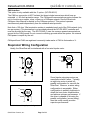
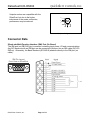
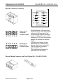
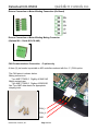
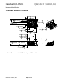
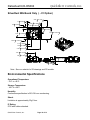
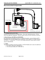
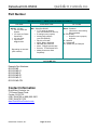
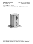
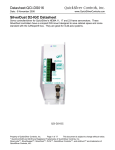
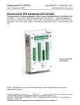
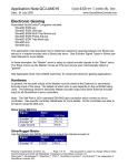
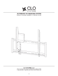
Datasheet:QCI-DS004 Date: 10 Dedember 2008 QuickSilver Controls, Inc. www.QuickSilverControls.com SilverDust M-Grade (MG) The SilverDust MG is a servo controller/driver for NEMA 17 & 23 frame microstep motors also know as a closed loop stepper motor controller. The SilverDust MG-C adds a CAN port which supports CANopen® protocols. (See Below.) QCI-D2-MG QCI-D2-MG-01 Property of QuickSilver Controls, Inc. Page 1 of 13 This document is subject to change without notice. QuickControl® and QCI® are Registered Trademarks of QuickSilver Controls, Inc. SilverLode™, SilverNugget™, SilverDust™, PVIA™, QuickSilver Controls™, and AntiHunt™ are trademarks of QuickSilver Controls, Inc.. QuickSilver Controls, Inc. Datasheet:QCI-DS004 System Overview Point-to-Point Moves • Relative or Absolute • Velocity or Time Based • S-Curve Advanced Motion Profile Moves • Profile Move Commands • Register Based o Position/Accel/Decel/Vel o Modify On-the-Fly Multi-Axis Linear Interpolation • XYZ Coords Contained in Text File • CANopen® used for local bus • 1000+ Points Stored In NV Memory Input/Output • 7 TTL Digital I/O o Use for QCI-BO-B52 24V I/O • 4 Analog Inputs (Joystick) • Analog Output Option • Programmable Limit Switch (PLS) • Secondary Encoder In Program and Data Storage • 32K Non-Volatile Memory: • 2000-3000 Program Lines • User Data Examples o CAM Tables o Motion Profiles o Lookup Tables Electronic Slip Clutch/Brake • Variable Torque • Wind/Unwind Applications Anti-Hunt™ • Optionally use Open Loop While Holding • No Servo Dither While At Rest QuickSilver Controls, Inc. Page 2 of 13 Electronic Gearing/Camming • Follow Encoder (A/B Quadrature) or Step and Direction • Dynamic Gear Ratios o Integer Ratios 32767:1 to 1:32767 o Decimal Ratios to 7 Places • Electronic Cam o Import Tables From Text File o Over 2500 Points o Multiple Tables Communications • RS-485/RS-232 @ 230K Baud • ASCII,Binary,Modbus®,DMX512 • CANopen® Option • Host Control While Servo in Motion Programming Language • Easy, Menu Driven Interface • Command Parameter Prompts • No Syntax Errors • User Namable I/O and Registers Advance PVIA™ Servo Loop • 100:1 Inertial Mismatch • Direct Drive Oversized Inertial Loads o Flywheels/Belt Drives o Typically Without Gearheads • More Stable Than PID Digital 4 Quadrant Vector Drive • DSP Driven for Reduced Noise Multi-Task/Multi-Thread Compatible with QCI Motor/Encoders • NEMA 11 Frame o 4000 Counts/Rev Encoder o Up To 9 oz-in (continuous) • NEMA 17 Frame o 8000 Counts/Rev Encoder o Up To 43 oz-in (continuous) o IP50 or IP65 • NEMA 23 Frame o 8000 Counts/Rev Encoder o Up To 300 oz-in (continuous) o IP50 or IP65 UL, CUL, CE Datasheet:QCI-DS004 QuickSilver Controls, Inc. Electrical Specifications Input Power Voltage +12 VDC to +48 VDC, regulated. Device must be initialized for the actual operating voltage. Over-Voltage Protection None available. Voltages exceeding +55 VDC will permanently damage the controller/driver electronics. Supply inputs may require active voltage clamping for aggressive braking/deceleration motions or applications with high inertial loads. See the Voltage Clamp Module technical document, (QCI-TD017), for more information on the voltage clamp. Reverse Polarity Protection None available. Connecting supply voltage in reverse can damage controller and the driver circuitry. However, limiting the supply current externally, to 5 Amps or less, will greatly minimize the chance of hardware failure. Input Current 4 Amps maximum for any input voltage, +12 VDC to +48 VDC. Output Power Output/Driver Current 3.5 Amps continuous per phase *; 4.5 Amps peak per phase *. * With Adequate Heat Sink. Maximum Output Power 150 Watts continuous power with adequate heat dissipation. Encoder Interface Permissible Primary Encoder Resolutions 1000 Lines = 4000 counts/revolution 2000 Lines = 8000 counts/revolution 4000 Lines = 16000 counts/revolution Primary Encoder Index or Z Channel QCI recommends obtaining an encoder with an Index or Z channel for use with the SilverDust. The index allows the SilverDust to perform minor alignment corrections while in motion. Property of QuickSilver Controls, Inc. Page 3 of 13 This document is subject to change without notice. QuickControl® is a registered trademark of QuickSilver Controls, Inc. Other trade names cited are property of their explicit owner. QuickSilver Controls, Inc. Datasheet:QCI-DS004 Inputs & Outputs Digital Inputs 0 or +3.3 VDC. TTL level compatible. Active low (sinking). Effective internal 200K ohm impedance to +3.3 V. Digital Output Voltage 0 or +3.3 VDC. Digital Output Current Sinking or Sourcing I/O 1, 4, 5, 7 outputs 4 mA MAX I/O 2 and 3 outputs 2 mA MAX I/O 6 outputs 8 mA MAX I/O Over-Voltage Protection Each I/O line is protected by series over-voltage limiting circuitry. External (Secondary) Encoder Maximum Bandwidth 1 million counts per second Analog Inputs 0 to +3.3 VDC input signal range. 10 bit ADC resolution (single). 11 bit ADC resolution (differential). Analog inputs 1 to 4 are mapped to share digital I/O lines 4 to 7. Each input has an effective internal 200K ohm impedance to +3.3 VDC. Analog signals are read every servo cycle (120 µsec.) and the converted analog data is processed through a 5 ms filter to reduce noise & transients. Communications Hardware Interfaces RS-232, RS-232 multi-drop, or RS-485 multi-drop (software selectable). Protocols 8-bit ASCII, 9-bit binary, DMX512, or Modbus Communication Line Protection Each line is protected with MOV clamping devices. Hardware Configuration Settings Available Baud Rates: 2400, 4800, 9600, 19.2k, 28.8k, 57.6k, 115.2k or 230.4k (250k DMX only) Data Bits: 8 Stop Bits: 1.5 or 2 Parity Bit: None QuickSilver Controls, Inc. Page 4 of 13 QuickSilver Controls, Inc. Datasheet:QCI-DS004 CAN interface This option is only available with the -C option. (QCI-D2-MG-C) The CAN bus connection is NOT isolated, but does include transceivers which have an extended +/- 80v fault protection range. The CANopen® communications protocol allows the unit to function as a master, slave, or peer on a CANopen network. See the SilverLode CANopen User Manual for details on the CANopen protocol. This protocol operates simultaneously and independently from the standard serial protocols. Note that a 120 ohm 1/2w termination resistor is needed at each end of the CAN network (only two per system). This termination is not provided onboard the QCI-D2-MG-C controller and must be provided by the user. The QCI-D2-MG-C uses the common power/communications ground as the CAN ground. Do not connect conflicting grounds within the system. No external CAN power is require by the unit. CANopen® and CiA® are registered community trade marks of CAN in Automation e.V. Stepmotor Wiring Configuration Ideally, the SilverDust will be interfaced with a four wire bipolar motor. A+ A+ A- M A- M B+ B- Four Wire Bipolar Configuration B+ B- 8 Wire Parallel Wiring Bipolar Configuration A+ M A- B+ B- 8 Wire Series Wiring Bipolar Configuration QuickSilver Controls, Inc. Page 5 of 13 Some bipolar microstep motors are manufactured with 8 wires. Typically, an eight wire motor is wired in a parallel configuration for use with the SilverDust. However, a series wiring configuration is acceptable. Either configuration is perfectly legitimate to obtain the best motor characteristics and achieve optimum performance. If the driver is capable of drivering the parallel configuration (current rating), then this mode usually provides superiour performance. QuickSilver Controls, Inc. Datasheet:QCI-DS004 Unipolar motors are compatible with the SilverDust, but due to the higher inductance of the series connection, performance may be reduced. A+ M n/c A- B+ n/c B- Unipolar Configuration Connector Data SilverLode Multi-Function Interface (SMI) Port (On Board) The SMI port is a DB15HD (pin) connector containing input power, I/O and communications. Any QCI breakout with an SMI port can be connected to this port via an SMI cable (QCI-ECSMI-nn). Alternately, the Basic Breakout (QCI-BO-B) attaches directly to the SMI port (no cable). SMI Pin Layout Front View on SilverDust 1 6 11 5 10 QuickSilver Controls, Inc. Page 6 of 13 QuickSilver Controls, Inc. Datasheet:QCI-DS004 Encoder Connector (On Board) Jumpering for Differential Encoder Signals Jumpering for Single-Ended Encoder Signals Either Differential or Single-Ended encoders may be used. The jumpers at the lower left hand side of the controller select between these two modes. In Differential mode, an AC terminator of 120 ohms is connected between the positive and inverted signals. In Single-Ended Mode, only the positive signal is used while the negative signal input is grounded. The 485 receiver is biased to approximately 1.56v. The board comes jumpered for Differential from the factory. Encoder Mating Connector and Pins (Optional Kit – PN # QCI-CK-5AS) QuickSilver Controls, Inc. Page 7 of 13 QuickSilver Controls, Inc. Datasheet:QCI-DS004 Drivers Connection or Motor Winding Connection (On Board) Drivers Connection or Motor Winding Mating Connector (Optional Kit – Part # QCI-CK-4AS) CAN Communications Connection -C option only A three (3) pin header is provided on MG controllers ordered with the –C (CAN) option. The CAN pinout is shown below. Mating connector is: Tyco AMP 770602-3 DigiKey A19491-ND Mating contacts are: Tyco AMP 770666-2 Digikey A23962-ND See Tyco AMP data sheets for appropriate crimping tools. CAN_L CAN_H GND QuickSilver Controls, Inc. Page 8 of 13 QuickSilver Controls, Inc. Datasheet:QCI-DS004 Mechanical Specifications SilverDust MG With L-Bracket 2.88 73.0 mm .13 3.2 mm .96 24.3 mm .72 18.3 mm n.138 n3.51 mm 2.38 60.3 mm 1.67 42.4 mm 1.91 48.4 mm n.118 .75 19.0 mm n3.00 mm 2.50 63.5 mm 2.25 57.1 mm 3.00 76.2 mm 2.88 73.0 mm 2.25 57.2 mm .75 19.1 mm n.118 1.50 38.1 mm 1.16 29.4 mm 1.38 34.9 mm .47 11.9 mm .13 3.2 mm Note: See our website for 2D drawings and 3D models. QuickSilver Controls, Inc. n3.00 mm Page 9 of 13 QuickSilver Controls, Inc. Datasheet:QCI-DS004 SilverDust MG Board Only ( - 01 Option) 2.05 52.1 mm .11 2.8 mm 2.50 63.5 mm .24 6.0 mm 2.39 60.7 mm .94 23.9 mm 1.93 48.9 mm 1.62 41.2 mm 1.89 48.1 mm .11 2.7 mm .74 18.8 mm 2.24 57.0 mm 1.50 38.1 mm .60 15.2 mm .75 19.1 mm .02 .5 mm Note: See our website for 2D drawings and 3D models. Environmental Specifications Operational Temperature -10 C to +80 C Storage Temperature - 40 C to +85 C Humidity Continuous specification is 95% RH non-condensing. Shock Limitation is approximately 50g/11ms. IP Rating IP20 with cables attached. QuickSilver Controls, Inc. Page 10 of 13 QuickSilver Controls, Inc. Datasheet:QCI-DS004 Recommended Components 5. Power Supply + _ 1. Controller/Driver QCI-D2-MG 2. Breakout QCI-BO-B 4. Motor Generic Motor with Encoder 1. Controller/Driver (QCI-D2-MG) Standard SilverDust MG servo controller/driver. This is the L-bracketed version. All other options are application dependent. See part number section for more information on options. 2. Basic Breakout (QCI-BO-B or QCI-BO-B52) QCI recommends purchasing a breakout to simplify wiring power, communications and I/O. QuickSilver offers several breakouts (see our website), but the simplest is our Basic Breakout (QCI-BO-B). To convert the 7 TTL I/O to 5 24V isolated inputs and 2 open collector outputs, select the QCI-BO-B52. 3. Cables The cables are specific to the motor selected. If a QCI M-Grade motor is used, the cables are: • 5 Pin Motor Cable (QCI-C-1BS-4AS-10) • 10 Pin Encoder Cable (QCI-C-2BS-5AS-10) QuickSilver Controls, Inc. Page 11 of 13 QuickSilver Controls, Inc. Datasheet:QCI-DS004 4. Motor The SilverDust D2 is capable of driving any a 17 or 23 I-Grade motor/encoder. See the following datasheets for more information: QCI-DS007: NEMA 17 I-Grade Motor/Encoder QCI-DS008: NEMA 23 I-Grade Motor/Encoder 5. Power Supply Power supply selection is motor dependent, but the following will work with all the 17 and 23 frame motors. S-210-48 (48V, 4.4A, 210 Watt) Other Recommendations SilverLode User Manual & Command Reference (QCI-SLM) For beginning and brand new users, please see chapter 1 User Manual for getting started instructions. The SilverLode user manual is in a textbook format. It begins with the fundamentals of use and progresses into advanced topics that are application oriented. Any new user can follow the material in a natural progression of product usage. In addition, there are exercises throughout the text that provide users a hands-on approach toward understanding the topics better. The manual is thorough, but not exhaustive. Users that explore this material fully and complete the exercises should gain the ability to operate, program, and prototype any SilverLode servo system into working applications. Both the user manual and command reference are available for download on our website. QuickSilver also sell hard copies of the SilverLode User Manual & Command Reference set under part number QCI-SLM. Clamp Module (optional) Some rapid acceleration and deceleration applications may require a clamp module. See technical document QCI-TD017 on our website for more details. Software QuickControl QuickControl® allows developers to quickly program and operate all SilverLode family of products using a standard PC running Windows (9x, Me, NT, 2K, or XP). Communication to the SilverLode controller/driver products is accomplished from the PC's serial port (i.e. COM1 or COM2). QuickControl also provides tools for uploading and downloading programs and user data. Data can be typed in manually or import from text files. Documentation features include remarks, line labels, namable registers and I/Os. QuickSilver Controls, Inc. Page 12 of 13 QuickSilver Controls, Inc. Datasheet:QCI-DS004 Part Number SilverDust™ MG Controller/Drivers DRIVER CONTROLLER QCI-D2 - 3.5 Amp • For 23 Frame and Smaller • 3.5 Amps per Phase Continuous* • 4.5 Amp Peak • Input Power: 4A@12V-48V * Depending on heat sink (25C ambient). MG – SilverDust D2 MG • 7 TTL Inputs or Outputs (use QCI-BO-B52 for 24V I/O) • 4 Analog Inputs (Joystick) • Analog Output Option (use QCI-BO-B1A) • RS-232 or RS-485 • ASCII, Binary, Modbus® • DB15HD (pin): SMI Port • Motor: Plugged terminal strip • Encoder: 10 Pin/Double Row • Mating Connectors Sold Separately OPTIONS Blank – Standard • L-Bracket for heat sinking. • DIN compatible 01 –Board Only • Requires user to properly heat sink. D – DMX512 C – CANopen® C1 – Board Only w/ CANopen Example: SilverDust MG board only with DMX512 and CANopen QCI-D2-MG-CD1 Example Part Numbers: QCI-D2-MG QCI-D2-MG-01 QCI-D2-MG-D QCI-D2-MG-D1 QCI-D2-MG-C1 QCI-D2-MG-CD1 Contact Information QuickSilver Controls, Inc. 712 Arrow Grand Circle Covina, CA 91722 (626) 384-4760 or (888) 660-3801 (626) 384-4761 FAX www.QuickSilverControls.com QuickSilver Controls, Inc. Page 13 of 13