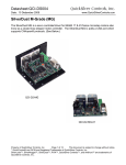
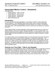
1
Application Note:QCI-AN019
Date: 24 July 2008
QuickSilver Controls, Inc.
www.QuickSilverControls.com
Electronic Gearing
Associated QuickControl® programs included:
SlaveSD EGM.qcp
SlaveSD EGM 32bit.qcp
SlaveSD EGM Multi Trap Moves.qcp
SlaveSD EGM Phase Adj.qcp
SlaveSD EGM Trap Move.qcp
SlaveSD.qcp
SlaveSN.qcp
This application note describes how to implement electronic gearing between two SilverLode
servos or a master encoder and a SilverLode servo. See Encoder Signal Types in SilverLode
User Manual for more details.
In these examples, the “Master” servo is setup to output encoder signals to the “Slave” servo.
The Slave moves as the Master moves as if the two servos were mechanically linked or
"geared".
See Application Note “QCI-AN029 Camming” for advanced electronic gearing applications.
Hardware
In general, the encoder output of the Master must be wired to the External (or secondary)
Encoder input of the slave. The details of which pins to use depends on the controller being
used. The following sections describes Master encoder output and Slave External encoder
input for all QuickSilver’s servo controllers.
Note: The SMI Port is QCI’s standard DB15HD (pin) connector which comes on all our
controllers. See specific controller datasheets for more details. All the controllers are able to
be slaves using the SMI port.
Slave Using SMI Port
Signal
Encoder "A"
Encoder "B"
Logic Ground
Slave
I/O
I/O 4
I/O 5
SMI Port
Pin 14
Pin 10
Pin 8
SilverNugget Master
Use the Modulo Set (MDS) command to output the internal encoder to:
Signal
Master
I/O
SMI Port
Encoder "A"
I/O 6*
Pin 5
Property of QuickSilver Controls, Inc.
Page 1 of 16
This document is subject to change without notice.
QuickControl® and QCI® are Registered Trademarks of QuickSilver Controls, Inc.
SilverLode™, SilverNugget™, SilverDust™, PVIA™, QuickSilver Controls™, and AntiHunt™ are trademarks of
QuickSilver Controls, Inc..
Application Note:QCI-AN019
Encoder "B"
Logic Ground
I/O 7*
QuickSilver Controls, Inc.
Pin 15
Pin 8
*4.7K pull-up resistors (I/O pin to +5 volt) should be added to increase signal integrity.
SilverDust MG/IGF/IGC Master
The SilverDust MG, IGC, and IGF do not have an encoder output option and can therefore not
be Masters.
SilverDust IG Master
The SilverDust IG always outputs it encoder on Aux connector pins 13,15 and 16. See QCIDS019 for details.
Signal
Encoder “A”
Encoder “B”
Logic Ground
Master
Aux Conn
Pin 15
Pin 13
Pin 16
SilverDust IGB
The SilverDust IGB always outputs its encoder on the breakouts terminals ENC OUT A,B,Z.
See QCI-DS003 for details. External encoder input is available from either the breakout
terminals ENC IN A,B,Z or from the SMI port.
Master
Signal
Encoder “A”
Encoder “B”
Logic Ground
Master
Breakout
ENC OUT A
ENC OUT B
Gnd*
Slave:
Standard SMI Port
or
Signal
Encoder "A"
Encoder "B"
Logic Ground
QuickSilver Controls, Inc.
Slave
I/O
I/O 4
I/O 5
Breakout
ENC IN A
ENC IN B
Gnd
Page 2 of 16
Application Note:QCI-AN019
QuickSilver Controls, Inc.
SilverDust IG8
The user can configure the IG8 to output its
encoder to the SMI port (I/O 4,5) using the
Encoder Monitor (EMN) command. See
Command Reference and QCI-DS018 for more
details.
Signal
Encoder "A"
Encoder "B"
Logic Ground
Master w/ EMN cmd
I/O
SMI Port
I/O 4
Pin 14
I/O 5
Pin 10
Pin 8
Gear Ratio (GR)
The GR of the Slave to Master is expressed as follows:
< Change in Slave Encoder (CS) >:< Change in Master Encoder (CM)>
<CS|CM>
For example a 1 to 2 GR would be expressed as 1:2 and would mean for every 2 encoder
counts of the Master, the Slave would move 1 encoder count.
Therefore a Gear Ratio of CS:CM would be
Gear Ratio (GR) = CS/CM = CS:CM
Slave Position (S)
Master Position (P)
S = GR * M
S = (CS/CM) * M
For 1:2 Gear Ratio example
CS = 1
CM = 2
GR = CS/CM = ½
S = GR * M = ½ * M
There are several ways of programming GR depending on what controller is being used. See
below for details.
QuickSilver Controls, Inc.
Page 3 of 16
Application Note:QCI-AN019
QuickSilver Controls, Inc.
Software
In order for a Slave to follow the Master's encoder, it must first be configured to read the
encoder and then to slave off it using a specific GR.
Select External Encoder (SEE)
On all the controllers, the SEE command is used to read the Master servo's encoder signals
through I/Os 4 and 5 in A/B Quadrature format or Step and Direction formats. Once SEE is
executed, the master encoder is automatically read in the background. The master encoder
value is also stored in register 200. See example programs below for usage information.
Gear Ratio Commands
Registered Step and Direction (RSD) and Electronic Gearing Mode (EGM) can both be used to
specify a GR and start electronic gearing.
RSD
Simple
Available on both SilverDust
and SilverNugget
Specify GR as interger ratios
i.e. 1:3
QuickSilver Controls, Inc.
EGM
Advanced
Available on SilverDust Only
Specify GR as decimal
i.e. 1:1.234567
Optional: Acceleration Factor
An acceleration ramp can be specifed
to change between GR.
Optional: Trapezoid Move
A trapezoid move can be triggered to
advance/retard a specified distance in
addition to base GR.
Page 4 of 16
Application Note:QCI-AN019
Registered Step And Direction
(RSD)- SilverDust Rev 32
CM and CS are stored in the upper and lower
words of the SF register specified by the RSD
command. This allows for easy entry when both
CM and CS are integers (i.e. GR=CS/CM=1:3).
RSD SF Register
Upper Word
Change in Master
Encoder (CM)
Lower Word
Change in Slave
Encoder (CS)
CM may range from 1 to 32767 and CS may range
from -32768 through 32767. A negative CS
causes the slave to move in the opposite direction
as the master.
Note, a GR of 1000:2000 is the same as 1:2,
therefore setting CS and CM to 1 and 2 will have
the same affect as setting them to 1000 and 2000.
The example to the right (SlaveSD.qcp), GR=1:2
(CS=1, CM=2). RSD's SF registers is register 11.
QuickSilver Controls, Inc.
Page 5 of 16
QuickSilver Controls, Inc.
Application Note:QCI-AN019
QuickSilver Controls, Inc.
Registered Step And Direction (RSD)- SilverNugget and
SilverDust Pre Rev 32
An older implementation of RSD defines the SF register as follows. Note this implementation
is the only option for the older SilverNugget controllers.
SF = GR * SF1
SF1 is the Scale Factor for a 1:1 gear ratio. SF1 depends on encoder resolution as follows:
4000 CPR; SF1 = 1024
8000 CPR; SF1 = 512
16000 CPR; SF1 = 256
Example:
If the Slave has an 8000 counts per revolution (CPR)
encoder and the desired GR is 1:2, what should be
stored in the SF register.
Step 1. Determine the SF1.
The Slave’s encoder is 8000 CPR so SF1=512.
Step 2. Calculate SF Value.
SF = GR * SF1
SF = 1/2 * 512
SF = 256
QuickSilver Controls, Inc.
Page 6 of 16
Application Note:QCI-AN019
QuickSilver Controls, Inc.
Electronic Gearing Mode (EGM) - SilverDust Rev 34
EGM provides high-resolution electronic gearing capability including the ability to smoothly
transition between different gear ratios.
The basic EGM command requires two registers. See below for advanced Trapezoid Move.
Scale Factor (SF) Register
The Scale Factor (SF) register is Gear Ratio multiplied by 10,000,000 to provide a range of +/200 with 7 places behind the decimal point. The upper limit will depend upon the motor
encoder resolution and the allowable output shaft motion for each Master count.
SF = GR * 10,000,000
Acceleration Factor (AF) Register
The Acceleration Factor (AF) register is used to limit the rate of change of the Internal Scale
Factor (ISF). ISF is the internal or actual scale factor used by EGM while SF is the desired or
target scale factor. Normal usage has a positive value for AF.
When first initialized, the ISF starts at 0. For each count change in the "Master" position, ISF is
moved in the direction of SF by AF counts. Once running, when the SF register is changed, the
ISF smoothly ramps from its previous value to the new requested value over a number of
Master counts.
In the example “SlaveSD EGM.qcp”
SF=10,000,000 (1:1)
AF=10,000
Then ISF will ramp from 0 (stopped) up to
SF=10,000,000 (1:1) over 1000 Master counts.
Note: if the input is oscillating back and forth, these
movements count as excursions and the ISF will
grow without regard to the direction of the motion.
Setting AF to a negative value will act as if a Stop
Condition was met, causing the EGM to ramp to a
stop using the absolute value of AF. This will also
cause the EGM command to end regardless of the
“End Command When Stopped” option setting. If
the continuous operation is desired, then set the
SF register to zero, which will cause ISF to ramp to
zero, but will not cause the motion to end.
A value of zero for the Acceleration Factor is
flagged as an error, and will
cause the EGM to ramp down fairly quickly and to
end.
QuickSilver Controls, Inc.
Page 7 of 16
Application Note:QCI-AN019
QuickSilver Controls, Inc.
If the user does not want the command to smoothly ramp between values, but
to rather operate as just a fixed scale factor, set the Acceleration Factor
to larger than the largest expected Scale Factor (i.e. 100,000,000) and the
ramping will all occur with a single count of motion.
See below for description of Options.
EGM-Trapezoid Move - SilverDust Rev 37
When “Enable Trapezoid Move” is checked, the EGM advanced Trapezoid Move option is
enabled.
Requirements:
QuickControl Rev 4.64
SilverDust Rev 37
The Trapezoid Move option provides the highresolution electronic gearing capability of the
EGM command plus the ability to add an
electronically geared Trapezoid Move while the
background gearing is under way.
A set of seven registers is required to configure
EGM and the Trap Move. With the Starting
Register=N, the seven registers are as follows:
Background EGM Registers:
• Register N = Acceleration Factor (AF)
• Register N + 1 = Scale Factor (SF)
For a given Gear Ratio (GR), SF = Gear Ratio (GR) * 10,000,000.
Trapezoid Move Registers:
• Register N + 2 = Start Position (SP)
• Register N + 3 = Master Distance (MD)
• Register N + 4 = Master Ramp Distance (MRD)
• Register N + 5 = Trapezoid Move Distance (TMD)
• Register N + 6 = Master Modulo Distance (MMD)
These registers are described in detail below.
Note: During the move, only the background EGM registers (AF, SF) can be updated. The
Trap Move registers are only sampled when the command is started.
The Trap Move works in both directions. If the modulo option is enabled, continuous forward
motion will allow repeated trapezoids to be commanded, otherwise the trapezoid will only be
executed as the Master transitions through Master Distance (MD).
QuickSilver Controls, Inc.
Page 8 of 16
Application Note:QCI-AN019
QuickSilver Controls, Inc.
Note: The EGM command utilizes registers 170 through 192 for its internal operations. The
user should not alter these registers while the EGM command is operating.
Register Definitions
Acceleration Factor (AF) (Starting Register N)
Scale Factor (SF) (Register N+1)
These are described above.
Start Position (SP) (Register N+2)
SP is used to locate the Trap Move with respect to the Master position count in register 200.
This trapezoid may be located at ether an absolute position or relative to the current value in
register 200. The Trap Move is located either positive from the starting point or negative from
the starting point according to the sign of MD (see below).
Master Distance (MD) (Register N+3)
MD may be positive or negative, according to the intended direction of motion of the master. A
positive value will locate the Trap Move motion positive of Start Position (SP), while a negative
value will locate the Trap Move motion negative from SP.
Master Ramp Distance (MRD) (Register N+4)
MRD defines the number of Master counts the Trap Move will accelerate/decelerate over.
MRD must be positive, and must be less than half of the absolute value of Master Distance
(MD) - that is, the acceleration and deceleration ramps must fit within MD.
Trapezoid Move Distance (TMD) (Register N+5)
TMD is the total extra counts the Slave will move the Master position count (register 200) has
transitioned across the selected MD in the specified direction.
Master Modulo Distance (MMD) (Register N+6)
MMD allows register 200 to be modulo’ed. Note: this modulo is only realized outside the region
of the Trap Move motion, thus the MMD must be greater than MD and the Trap Move starting
position, SP, must also be consistent with MD. A single add or subtract is calculated each
cycle (when not inside the trapezoid), so it may take a considerable amount of time to initially
reach the valid modulo range if register 200 contains a large value when the modulo is first
engaged.
QuickSilver Controls, Inc.
Page 9 of 16
Application Note:QCI-AN019
QuickSilver Controls, Inc.
Options - QuickControl
The Trapezoid Move has the following options.
End Command When Stopped
Set this option to end the command when the Trap
Move has completed and servo is commanded to zero
velocity (SF=0) and stops (actual velocity=0). Note, if
Trap Move enabled, option “One Trapezoid Move Only”
must be set for this option to work.
Override Existing Move
Set this option to have EGM override any existing move commands (requires multi-tasking
enabled).
Do Not Override Trapezoid Move
Do not override if Trap Move is still active. When used in conjunction with “Override Existing
Move”, the option allows the prior Trap Move to complete while keeping the background EGM
operation active.
On Stop Conditions, Only Stop Trapezoid Move
If unchecked, all motion is stopped and EGM exits if a Stop Condition is met.
If checked, only Trap Move is stopped when Stop Condition is met. EGM continues.
One Trapezoid Move Only
If checked, once the Trap Move completes, it will not repeat even if the Master count reverses
or Master Modulo Distance is enabled.
QuickSilver Controls, Inc.
Page 10 of 16
Application Note:QCI-AN019
QuickSilver Controls, Inc.
EGM Mode Word (non-QuickControl)
The Mode parameter is edited by QuickControl. The following bit definitions are provided for
those users who are not using QuickControl.
Bit #
0
1
2
3
4
5
6
Description
End Command When Stopped
see Options above
Override Existing Move
see Options above
Do Not Override Trapezoid Move
see Options above
NOTE: Only valid if bit 4 set
Must be set to 1.
NOTE: EGM has the same command number as PVC (cmd=93). The
command is EGM if this bit=1 and PVC if this bit=0.
1 enables the Trapezoid Move
0 causes the Trapezoid start position to be Relative; 1 causes the
Trapezoid start position to be absolute. Input value is Register N+2
NOTE: Only valid if bit 4 set
1 enables the Modulo operation, allowing the Trap Move to repeat
multiple times. Register 200 is automatically modulo’ed by Register N +
6. This may take some time to initially adjust if register 200 has a large
value. This Modulo is only adjusted between trapezoid moves.
7
NOTE: Only valid if bit 4 set
On Stop Conditions, Only Stop Trapezoid Move
see Options above
8
NOTE: Only valid if bit 4 set
One Trapezoid Move Only
see Options above
NOTE: Only valid if bit 4 set
QuickSilver Controls, Inc.
Page 11 of 16
Application Note:QCI-AN019
SlaveSD EGM Trap Move.qcp
This example will help clarify the Trap Move
parameters and how they affect a motion.
In this example, the Slave will move an additional
6000 counts every 10000 Master counts.
Lines 9-21: Initialize Trapezoid Move Parameters
The seven EGM registers are initialized prior to
executing EGM.
Line 23 Execute Trapezoid Move
The move is executed in the background because of
the Enable Multi-Task Command (EMT) command at
the top of the program.
EGM is configured as follows:
QuickSilver Controls, Inc.
Page 12 of 16
QuickSilver Controls, Inc.
QuickSilver Controls, Inc.
Application Note:QCI-AN019
The following chart of Slave Position with respect to Master Position shows how the Slave
moves as the Master changes from 0 to 18000.
EGM w/ Trapezoid Move
SP
MMD
20000
Slave Position
16000
MD
12000
MRD
GR
8000
TMD
4000
0
-2000
0
2000
4000
6000
8000
10000
12000
14000
16000
18000
Master Position
The following table details each transition point.
Master
Position
0-2000
2000
2000-3000
3000-5000
5000-6000
6000
6000-10000
10000
Internal Gear Ratio (IGR)1
Description
IGR = GR = 0.5
IGR = GR = 0.5
IGR = 0.5 to Trap Move GR 2
IGR = Trap Move GR 2
IGR = Trap Move GR 2 to 0.5
IGR = GR = 0.5
IGR = GR = 0.5
IGR = GR = 0.5
Base Gear Ratio (GR)
Start of Trap Move
Ramp up to Trap Move GR 2
1
Ramp down to GR
Trap Move Complete
Base Gear Ratio (GR)
End of Modulo
Internal Gear Ratio (IGR) is the actual GR being used. The controller calculates this based
on the Base Gear Ratio (GR) and what part of the Trap Move is currently being executed.
2
Trap Move GR is calculated internally by the controller to achieve the TMD in the given MD.
QuickSilver Controls, Inc.
Page 13 of 16
Application Note:QCI-AN019
QuickSilver Controls, Inc.
SlaveSD EGM Phase Adj.qcp
This example shows how to follow a master encoder
with the additional ability to adjust the phase. In
particular, the Slave will advanced an additional 1000
counts every time I/O #1 goes LOW.
Lines 9-19: Initialize Trapezoid Move Parameters
In this example, only 6 of 7 EGM registers are
required because EGM modulo feature is not being
used.
Line 21 EGM
EGM is executed in the background. Note, the Trap
Move is not enabled, so this EGM simply sets GR to
0.5 and starts moving.
Line 24 WBE
Wait for I/O #1 to transition from HIGH to LOW.
Line 25 EGM – Advance 1000 Counts
This second EGM is configured as follows to override
the previous EGM at the same base GR but with a
1000 count Trap Move.
Note, both “Override Existing Move” and “Do Not
Override Trapezoid Move” are checked. This will
cause this EGM to override the previous EGM, but it
will not interrupt any unfinished Trap Moves.
Note, “One Trapezoid Move Only” is checked to ensure that the Slave will not “retard” 1000
counts if, after completing the Trap Move, the Master reverses.
QuickSilver Controls, Inc.
Page 14 of 16
Application Note:QCI-AN019
QuickSilver Controls, Inc.
SlaveSD EGM Multi Trap Moves.qcp
This example shows how to follow a master encoder
with the additional ability to adjust the phase. In
particular, the Slave will advanced an additional 1000
counts every time I/O #1 goes LOW.
Lines 7-13: Initialize Trapezoid Move Parameters
In this example, only 6 of 7 EGM registers are
required because EGM modulo feature is not being
used.
Note, AF and SF=0. This means that the Base Gear
Ratio (GR) = 0. In other words, the Slave will only
move the Trapezoid Move Distance (TMD) when
triggered.
Line 15-16 1st EGM
Move 2000 counts over a Master Distance (MD) of
16000 counts.
Line 17-18 2nd EGM
Move -2000 counts over a Master Distance (MD) of
16000 counts.
Since “Do Not Override Trapezoid Move “ is checked,
each EGM will wait for the previous EGM’s Trap Move to complete before executing a new
Trap Move.
QuickSilver Controls, Inc.
Page 15 of 16
Application Note:QCI-AN019
QuickSilver Controls, Inc.
SlaveSD EGM 32bit.qcp
This example shows how to dynamically calculate very accurate gear ratios.
The SilverLode servos deal only in integers, so calculating a gear ratio like:
GR = 123.456 to 789.123 (123.456/789.123)
requires some extra manipulation.
1) Multiply GR’s numerator and denominator by 1000 to get rid of the fractions.
GR = 123456/789123
2) Since SF = GR*10,000,000, multiply numerator by 10,000,000 first then divide by
denominator. This has to be done in this order or resolution will be lost do to truncation.
SF = 123456 * 10000000/789123
The only problem with the above method is that the resultant of
123456 * 10000000
is greater than 32 bits which means it cannot be held in a normal 32 bit register.
The CLX command solves this by providing a 32x32 multiply that puts the resultant into a pair
of 32 bit registers. For division, CLX has a 64/32 operation.
Line 5: Numerator (reg 25)
Line 6: Denominator (reg 26)
Line 7: 32x32
Store
reg 25 * 10,000,000
into reg 27/28.
Line 8: SF
Divide 64 bit value stored in reg 27/28 by reg 26 and store as
SF in reg 31.
QuickSilver Controls, Inc.
Page 16 of 16