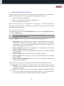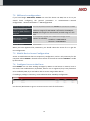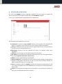
1
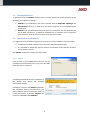
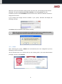
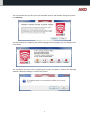
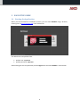
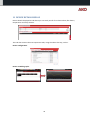
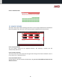
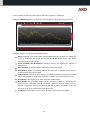
5010H002 Ed.02 GB AKONet Monitoring and supervision software for refrigerated facilities User manual Index 1 2 3 4 5 6 7 8 9 10 11 12 13 14 15 16 17 18 19 20 INTRODUCTION.................................................................................................................................... 3 PRODUCT INSTALLATION ..................................................................................................................... 4 EASY SETUP GUIDE............................................................................................................................... 9 USER AND GROUP CREATION ............................................................................................................ 13 SERVICE CONFIGURATION ................................................................................................................. 14 DOCUMENT MANAGEMENT FOLDER CONFIGURATION .................................................................... 15 CONNECTIVITY CONFIGURATION ...................................................................................................... 16 DEVICE REGISTRATION....................................................................................................................... 18 SERVICES ............................................................................................................................................ 20 DEVICE LIST ........................................................................................................................................ 21 DEVICE DETAIL DISPLAY ..................................................................................................................... 23 GRAPH VIEWER .................................................................................................................................. 24 REPORTS ............................................................................................................................................ 27 SYNOPTICS ......................................................................................................................................... 29 DOCUMENT MANAGEMENT .............................................................................................................. 31 TASK PLANNER ................................................................................................................................... 33 ALARMS ............................................................................................................................................. 37 BACKUPS ............................................................................................................................................ 38 UPDATES ............................................................................................................................................ 39 SYSTEM VARIABLES ............................................................................................................................ 40 2 1 INTRODUCTION 1.1 Welcome to AKONet Welcome to AKONet, AKO's new monitoring, supervision and control software. AKONet has been designed since its conception to be accessible and very easy to use, but very efficient and capable of scale up to the largest projects. This guide is aimed at introducing the user to the software and its architecture, allowing starting quickly and then providing all the necessary resources for getting the most out of it. 1.2 Licence and Demo Mode 1.2.1 How does the Demo mode work? AKONet can be used for two hours running without any restriction, and after this demo period the system will stop most of the functions such as communication with the devices for example. Rebooting the system obtains a further two hours of execution and so on. 1.2.2 How does the licence work? The licence system is based on an USB dongle that contains the product activation, just inserting the dongle into the USB slot of the server where the software was installed, the licence will be activated and you can use the software without any time restrictions. The dongle should always be inside the USB slot, as if not it will return to the demo mode with the aforementioned restrictions. If you do not have a software licence USB dongle, contact your usual dealer for them to send you one. 3 2 PRODUCT INSTALLATION Before installing the product, read the following minimum requirements and incompatibilities thoroughly. 2.1 Minimum System Requirements 2.1.1 Compatible Operating Systems Windows XP SP3 Windows Vista Windows 7 2.1.2 Requirements Intel Core 2 processor at 2.40 GHz (or equivalent). 1 GB of RAM (2 GB recommended). 1 GB hard disk for the installation 100 Mb of hard disk per connected device/year. Screen resolution: 1024 x 768 CD-ROM 3 available USB ports Google Chrome Web Browser recommended although it works with the Microsoft Internet Explorer 9, Mozilla Firefox 8 or later and Opera 11 browsers. 2.1.3 Web Browser It is important to point out that to get a better performance out of AKONet you will have to have the latest versions of the browsers in all the computers that are going to use the application. AKO recommends using Google Chrome as the browser for the AKONet software, and if you want to download it free, go to: http://www.google.com/chrome?hl=es 4 2.2 Incompatibilities To guarantee that the AKONet software works correctly, please pay special attention to the following points before installing it. AKONet is not compatible in the same computer with the AKO-5004, SOFTRegis and SOFTREGIS.H software, so make sure that these programs are not installed before installing it. AKONet uses the 5432 communications ports for connection with the database and 82 for Web connections, it should be validated that no software exists using these ports and also, checked that no security system blocks its usage. 2.3 Installation in Windows It is important to take the following points into account for the installation to be successful: Installation should be carried out by a user with administrator privileges. It is advisable to temporarily stop the antivirus and firewalls so that they do not block the installation process. The AKONet installation is made up of three steps: 2.3.1 Step 1 Insert the CD in the CD-ROM drive and wait for the installation to automatically start or go to the CD-ROM drive and click on setup.exe. If installing under Windows Vista or Windows 7, the system may display the following confirmation window: Click Yes to continue and AKONet will display the installation features window where you will be asked to select the drive and folder to install the product, by default, AKONet will install in C:\AKOSOFT\SOFTAKONET\. 5 When the system has finished installing all the necessary files, the following window will be displayed. This point is not the end of the installation, and clicking Finish starts the installation process of the AKO-80039 communication drivers and the installation of the free Google Chrome driver. If you already have Google Chrome installed in your system, Windows will display the following message: Click Close and the installation will continue normally. When the process has finished, the installation will ask you to reboot the system, and it is important to do this for the software to work correctly. 2.3.2 STEP 2 After rebooting the system, AKONet will automatically boot the configuration process, displaying a series of windows. The first window asks us to confirm that you are entering with a user with administration privileges, and if so, click Continue. 6 The next window tells you that you have to disable antivirus and firewalls during this process, click Continue. The next step allows configuring the default language of the language (you can change it later if you want). The installation will then finish configuring the system and when it finishes the following window is displayed asking us to reboot the system. 7 2.3.3 Step 3 When AKONet is started in step 3 and if you have not connected the AKO-80039 converter or the ILock licence dongle, AKONet will ask us to connect both devices: Once connected, AKONet will detect this automatically. Finally, AKONet will automatically open the application on a full screen. 8 3 EASY SETUP GUIDE 3.1 Starting the Application When you have finished the installation process, you can access AKONet using a browser, entering the url http://localhost:82/ in the address bar. The default user and password are: Default user: superuser Default password: superuser After entering the user and password, click the Login button and enter AKONet 's main window. 9 3.2 Application Work Area The application work area is divided into four parts: 3.2.1 General menu area This area contains the most important menu options of the application, and as you will see later on, the options are displayed or hidden depending on the privileges of the group the user is assigned to. The menu points are: Administration In this menu you will find all the application's setup options, and here you can maintain users, groups, services, document management folders ... Alarms This option will open the list of existing alarms, and you can confirm them, print them or change the filters to see the alarm log. Services The Services option displays all the devices you have registered graphically and ordered (using tabs) by the services you have registered. A service is a functional group of devices, for example, positive or negative cold rooms, and they are created to identify the device more easily. Devices It also displays the devices, but in a list mode with each ones' most important variables. In this section you will see that the devices are classified according to its model: CAMControls, where you will find all the AKO control devices. CAMRegis, it will display all the temperature data logger devices. AKODUO, the DUO family devices will be displayed. CAMAlarm, all the alarms will be listed. Graphs This option lets us enter the graph generation Wizard. Reports You can use this option to obtain all the reports (lists) of the samples of our devices. Synoptics It gives us access to the graphical representation module of the facilities. Documentary Management This last option allows accessing the place where the generated reports are stored. 10 Apart from these options, the top menu gives us six icons for performing a series of tasks easily and simply: When this icon is clicked the application will automatically go to the home screen. If you are on any screen of the application and you click this button, the system will save it to be the home screen for our user. It will open the details of the user you are logged on with and will let us change its details. On any screen, clicking this button makes the screen appear for entering a favorite. This favorite will be associated to our user and will be displayed on the side menu (up to a maximum of 10). It opens the application's help. Close the session and return to the login window. 3.2.2 Side menu The side menu shows the favorites you have associated using the top button with up to a maximum of 10 entries. When one of the options is clicked, the system will go to the option associated to this favorite. 3.2.3 Work area This is the middle area of the application, and it will be here where all the application's screens are displayed. 3.2.4 Bottom information bar Alarm events that occur are displayed in this area. 11 3.3 Obtaining reports AKONet provides a quick and simple way to obtain sample reports, and to do to so: 1. Select the device you want to get a report on from the Services tab. 2. Go to the Graph tab and select the samples you want to include in the report. In the example, the Set Point and Oven 4 sample is selected. 3. Click the Generate button that will present the graph with the last fortnight, and if you agree with the period go to step 5. 4. Click the Filter button and change the period you want to generate for the report. 5. Click the Print button, and then AKONet will generate the report made up of: a. Graph printing. b. Samples that make up the graph. c. Maximum, minimum and medium data for the selected period. 12 4 USER AND GROUP CREATION The next step for quick set up will be to create users and groups of users needed for the application to work properly. The aim of this task is to register the users that: 1. Are going to access the application. 2. Want to notify via SMS or e-mail the system's alarms. 3. Want to send reports via e-mails. Before creating the users, it is important to create groups of users and assign them permissions, in other words, it is important to prevent that all of the users can access the application without restrictions. 4.1 Group Maintenance To create the user groups, go to the Administration menu, click the Users and Groups option and select the Groups tab. Attention, the Administrator group should not be eliminated yet, as if so, you would eliminate the superuser. A series of AKONet functions can be allowed or refused for each group of users: Administration, this option gives or denies access to the Administration menu point, and allows or disables the synoptics creation or edition options, the document maintenance option in the document management module and, in general, any option for deleting general characteristics. Device configuration, access to the modification and configuration of the devices' modules can be controlled with this option. Access to Graphs, access to the graph generation function can be given or denied using this option. Access to Synoptics, gives or denies access to the synoptics module. Access to Reports, which users have access to the report module can be controlled with this option. Access to Document Management, who has access to the document management module can be controlled. As a general recommendation, it would be advisable to create at least two more groups: Operators who would have all privileges except for the Administration option. All users who need to modify any system variable such as the Set Point should be included for this group. Viewers that would have access to Administration and Device Configuration denied. All users whose daily job is exclusively monitoring and who in no case should have access to modifying system variables should be included for this group. 13 4.2 User Maintenance When all of the different groups have been registered, it will be the time to create the users who are going to use the system, and to do so access the Administration menu, click the Users and Groups option and select the Users tab. Attention: The Administrator group should not be eliminated yet, as if so, you would eliminate the superuser. Click the Add button to add new users. This button will open in a pop-up window the user registration tab, and you should include all of the user's data in this window. Important: Fill in the e-mail and mobile telephone fields so that the user receives alarm notifications by e-mail and/or SMS. The group you assign the user to should be paid attention to. 5 SERVICE CONFIGURATION Another important point to bear in mind in the initial configuration is the configuration of the services. A service is a logical way of grouping our devices, for example, you can classify the devices if they are going to service positive, negative or neutral cold rooms, or for example, they can be grouped according to location … This step is not compulsory, as the AKONet creates the service by default. To configure the services, access the Administration menu, click the General Configuration option and select the Services tab. By default, when a new service is added, it is visible for all user groups, but the groups you want that can display this service can be assigned when the service is added or modified. 14 6 DOCUMENT MANAGEMENT FOLDER CONFIGURATION The document management module allows storing all the documents regarding the installation of AKONet, for example sample reports, graphs, and any other document regarding the facility can be saved. If you want to use the document management module, it will be important to configure the folders then. To configure the document management folders access the Administration menu, click the General Configuration option and select the Document Folders tab. This step is not compulsory, as the AKONet creates the folder by default. 15 7 CONNECTIVITY CONFIGURATION An important element of AKONet is that it can emit alarms and reports via e-mail and sms (only alarms) and in the same way, you can access the application from any mobile device with a browser incorporated. You have to adjust some settings to configure each of these features: 7.1 E-mail service configuration Important: For AKONet to be able to send e-mails, it is essential that the computer it is installed in has access to the Internet. AKONet sends the e-mails via a SMTP server, which can be local or remote, and therefore access to a server of this type should be available to equip the AKONet with this function. To configure these parameters you should access: Administration -> General Configuration -> General Parameters -> E-mail configuration Where you find the following parameters: Send messages via e-mail Name of the SMTP server Connection port with the SMTP server SMTP server account user SMTP server account password This box should be ticked for the service to work. Write the name of the outgoing mail server. Write the port the outgoing mail server uses. Server account user Password Normally, this data is supplied by the mail server administrators, and if you need to know them, the easiest way is to copy this list for them to give it to you. 16 7.2 SMS service configuration If you have bought AKO-52043, AKONet can send the alarms via SMS, but to do so you should finish configuring the general parameters in Administration -> General Configuration -> General Parameters -> SMS Configuration Sending messages by SMS Communications port where the GSM modem is assigned SIM supplier message service centre SIM PIN number This box should be activated for AKONet to send alarms via SMS It should inform the communications port where the GSM modem is assigned, if AKO-52043 is inserted in the USB port, AKONet will recognise it automatically and will assign it in this field. Each telephony supplier has a different message centre number, for example: - Vodafone: +34607003110 - Movistar: +34609090909 Leave empty When you have registered the parameters, you should reboot the server for it to get the new configuration. 7.3 Mobile Device Access Configuration Access via mobile devices does not require any configuration, and it is only necessary for the computer where AKONet is housed to have access to the Internet and that AKONet is visible by the Internet. 7.4 Configure Access to the Users Each AKONet user can have sending messages by SMS or e-mail active or inactive, have or not access from mobile devices, by default, when a user is registered, they have permission to be notified by SMS, by e-mail and be able to access using mobile devices. If revoking a privilege is necessary, access Administration->Mobility configuration: Use the YES / NO buttons to give or remove access to each of the functions. 17 8 DEVICE REGISTRATION You now have AKONet correctly configured. Therefore, the next step is to register the devices connected to the modbus network using the AKO-80039 converter. To do so go to Administration->Registered Devices->New Device: The parameters the window asks us for are: Installation: If you have bought AKONet Advance, you can select the installation the device is assigned to, and on the contrary, leave it with the default installation. Service: It will display all the services you have registered previously, and pay attention to which service you assign the device to. Description: Include a text that identifies the device, for example Frozen Food, Vegetables … Location: You can assign a more specific location for the control. Bus address: You should indicate what bus address the device you are registering has, this step is important and causes a lot of errors. Model: You will assign the device's exact model. Generate DataLog: If you indicate YES, the system will obtain samples and log them to be able to make graphs and lists later on, but if you only want to monitor and are not bothered about the logs, you can assign a NO. Status: It should be active for AKONet to be able to communicate with the device, and if it is inactive, it will be saved in the database but no attempts to communicate with it will be made. Image: You should select an image from our hard drive or from the library, and this will allow you to visually identify the device quicker. 18 When registered, it will be displayed on the registered device list. If it is a device with memory, the logs will start to automatically download. From then on, the registered device will appear in AKONet. 19 9 SERVICES The application's general menu services option allows seeing the status of the facility graphically. This screen is divided into tabs, one per service you have registered and a further two tabs that display all of the devices and the ones that are offline. In this example AKONet has three services configured, Ovens, Ambient and Positive Cold Rooms, and it also shows you the All tab and the Offline Devices tab. When you click a service, the devices the application displays are the ones that belong to that service. This window is automatically updated after a period set in the general parameters (Administration->General Configuration->General Parameters->Application Refresh->Refresh seconds of the devices in the Services display). This parameter is set at 30 seconds by default. Therefore, you will se any change in the facility's situation indicated in this window. Each device is shown in the following format: If it is a device like a CAMRegis with more probes and without relay statuses, it will be shown in the following way: Clicking any device the application opens its detail. If an alarm occurs in a device, the device background will be displayed in RED. If communication errors occur in a device, the device background will be displayed in ORANGE. 20 10 DEVICE LIST The device list displays the devices in a list format, and this screen divides this display depending on the device type. This division is carried out by tabs that are grouped in four groups, CAMControls, CAMRegis, AKODUO and CAMAlarm. The division is basically carried out due to the display format, as the important data for each group are different, therefore for: CAMControls the following is displayed: o Alarm icon, that represents if the device has alarms or not. o Device description. o Service it belongs to. o Facility it belongs to. o Set Point Value o COOL relay status o DEFROST relay status (only for technical display) o FAN relay status (only for technical display) o Probe 1 value o Probe 2 value (only for technical display) o Probe 3 value (only for technical display) CAMRegis o Alarm icon, that represents if the device has alarms or not. o Device description. o Service it belongs to. o Facility it belongs to. o Probe 1 to 10 value (depending on the model, it will display more or less probes). AKODUO o Alarm icon, that represents if the device has alarms or not. o Device description. o Service it belongs to. o Facility it belongs to. o Probe 1 to 5. CAMAlarm o Alarm icon, that represents if the device has alarms or not. o Device description. o Service it belongs to. o Facility it belongs to. o Input 1 to 4. 21 You can generate the following actions for each device: Display the detail of the device clicking the Display Device button. Change the Set Point value (as long as the selected device has this feature). 22 11 DEVICE DETAIL DISPLAY Device detail is displayed as tab where you can easily see all of its relevant data, like alarms, temperature and relay statuses. This tab also accesses the most important tasks, using the tabs at the top, such as: Device configuration. Device variables graphs. 23 Device scheduled tasks. 12 GRAPH VIEWER The Graph menu option allows obtaining information on the samples obtained from the different devices in graph format, and to do so the system provides a Wizard based on three levels: Level 1. Device Selector You can browse around all the registered devices, and selecting a specific one will automatically load level 2. Level 2. Feature Selector This level loads with all the properties that generate the logs of the device selected in level 1. If you select one, it will go to level 3. Level 3. Selected Features All the features you select will be included here and you can include different features from different devices. 24 In this example the features of the Oven 1 and Oven 2 device are combined. Clicking the Generate button, the application directly goes to the graph viewer window: The graph allows carrying out the following options: Zoom: Selecting a part of the graph automatically generates a zoom of it. When the zoom is generated, the graph will display the Reset zoom option that allows returning to the original mode. Series activation and deactivation: Clicking a series in the legend can activate or deactivate it. Return button, clicking this button goes back to the home screen. Filter Button, where a contextual window will open with a calendar where you can select the start date and end date. Update Button, with a drop-down menu to be able to programme an automatic update where you will have the option Stop, 1 minute, 5 minutes, 15 minutes and 30 minutes. Print Button, that allows you to send the graph to PDF format. Save Button, the generated graphs can be saved as a photo or, just saving the defined series. Therefore, clicking this button displays a window where you can include a name (free text) to give to the graph and an option to indicate if you save the series or save the series and the specific period. List Button, it will display in a list format all the data contained in the graph. 25 The main graph generation window has two extra tabs: "Saved graphs" tabs Here all graphs that have been saved with defined periods from the save button will be displayed. The option of deleting this graph using a button will exist if you have administration privileges or if you have created this. "Preset graphs" tab Here all graphs that have been saved without defined periods from the save button will be displayed. The option of deleting this graph using a button will exist if you have administration privileges or if you have created this. 26 13 REPORTS The application's general menu Reports option allows extracting any information from any parameter of any device registered on which the DataLog option has been marked, and the format of the data extracted data is in the list mode. The main is divided into five tabs, which will allow us to extract the specific data you need to carry out. The tabs are Report Selector, Sample Reports, Alarm Reports and Other Reports. All tabs have the format of three levels in common for the selection of the features to be listed in the report, and this format is based on three levels: Level 1. Device Selector You can browse around all the registered devices, and selecting a specific one will automatically load level 2. Level 2. Feature Selector This level loads with all the properties that generate the logs of the device selected in level 1. If you select one, it will go to level 3. Level 3. Selected Features All the features you select will be included here and you can include different features from different devices. 27 In this example the features of the Oven 1 and Oven 2 device are combined. Clicking the Generate button makes the application go to the date range selection window, where you will be allowed to select the start date and end date, and reclicking Generate goes to the window where the report will be displayed. This window has four buttons in charge of exporting the list. It can be exported to the Document Manager (in PDF format), sent directly by e-mail (in PDF format), or downloaded to the computer in Excel or PDF. 28 14 SYNOPTICS The Synoptics Module is in charge of equipping AKONet with HMI (Human Machine Interface) functions. These functions allow users to display the information of their facility graphically using a group of controls that simulate the devices in it, dynamically. The functions of the new synoptic module are: Loading an image representing the drawing or structure of the synoptic. Freehand drawing of a drawing or structure of the synoptic. Representation of industrial controls using specific libraries. The graphical representation of the variables of the AKO devices can be included on this image (temperatures, relay statuses, alarm statuses, …) Easy access to the details of the device (current status, graphs and remote configuration). 14.1 Synoptics Design AKONet allows generating two different types of synoptics: Using a background image, this mode allows including a background image that represents the scenario you want to represent. Using a freehand drawing (only valid for browsers with SVG support such as Mozilla or Chrome), in this case AKONet allows creating freehand drawings. When a new synoptic is registered, you should define the type of synoptic you want to make, and also, each synoptic will have a description and an icon that represents it. The synoptics design tool provides an easy and intuitive way to generate from simple representations of the facility, to complex animations. It allows including a free text. It allows including a real value of a parameter of a device. Using this control previously created icons (like relay statuses, alarms…) can be included It allows creating objects based on the application's icon library. Using this option you can include controls that change their behaviour (colour) depending on the values that the device parameters take. 29 Clicking this icon, all the objects created in the synoptic can be moved. Clicking this icon, the objects can be resized. Clicking this icon, the object clicked after this icon will be deleted from the synoptic. If you are creating a synoptic with freehand drawing, the designer will display the following buttons: It allows drawing a line. It allows drawing a rectangle. It allows drawing a circle. It allows drawing an ellipse. It stops the drawing control. It opens the drawing options window, where you can select the fill colour and thickness of the line. 30 15 DOCUMENT MANAGEMENT The document management menu lets you save and recover documents regarding the facility, such as reports, images, PDF documents, etc., to have all of the information centralised. The document manager organises these files based on folders, and these folders can be created from the Administration->General Configuration->Document Folders menu. To do so, when you click the document management option on the main menu, it displays a screen with all the folders, and each folder is defined by a name and a description as well as the association of the amount of documents it contains. If you click on one of the folders, the application will display a list of the documents in this folder. A folder called All is also included where all of the documents will be displayed. The screen that lists the existing documents allows the option of filtering among the listed documents, allowing looking for any chain of text that is contained in the name of the document. Clicking the button downloads a copy of the file onto the computer. Clicking the button deletes this device from the document management module (only for administrators). 31 15.1 New Document Two methods can be used to insert new documents in the document management module: 1. New Document Option directly from the document management module will allow for uploading any document from the user's disk to AKONet. To do so click the New Document icon that will appear on the new document generation window. 2. From the Lists windows, a button called Document Management will appear in the application's lists, and clicking it opens a window for uploading the document. In this case, the system creates the document. For these two options a window similar to the following will be displayed: a) Group: (or folder) where you can select the folder where you want to insert the document using a drop-down menu. b) Title: it is a free text field used to indicate the document title. c) Description: free text for creating a small description explaining the document. d) Date Period: Allows indicating what dates the document is related to, and this is useful in lists for example. e) Document Type: The type of document that is going to be inserted should be indicated. f) Document: Field that allows uploading the document on to the system (only visible in option 1). 32 16 TASK PLANNER AKONet has a function that allows carrying out scheduled tasks according to a calendar. There are two types of tasks that can be scheduled, automatic report generation and modification of devices features and parameters. To schedule a new task go to Administration->Task Planner, where the following window will be displayed: 33 16.1 Automatic Report Generation Automatic report generation allows planning a task so that at a given moment a report is generated with the data of the parameters of one or several specific devices. In this way, the user does not have to obtain these logs. For example, a task can be scheduled so that at the beginning of each month samples from a given device are sent by mail and saved in the document management module. To do so, the scheduled task creation window presents the following features: Name: Free text that will allow identifying the task later on. Description: Free text that will allow identifying the task later on. Color: A color that will allow identifying the task later on can be indicated. Starts on: Indicates the date and time the task will occur the first time. Type: For reports, you should mark the Report button. Select the destination of the report: In these fields you can decide how to transmit the report, and it can be sent to: Document Management, indicating the destination folder. E-mail addressees, indicating one or several addresses separated by a comma. It is repeated: It allows identifying how often it will be repeated, the possible options are every day, every week, every month and every year, and if you decide to do it every 2 days it should be indicated in the following option. Repeat every X repetitions: This parameter can be used to indicate how often the event will be repeated, depending on what is indicated in the It is repeated selector. Ends on: You can indicate when this event will end, which can be Never, after N repetitions or on a specific date. 34 After registering the report, a window will be displayed that allows selecting the parameters that make up the report, and to do so it will display the format of three levels to select the features to be listed in the report: Level 1. Device Selector You can browse around all the registered devices, and selecting a specific one will automatically load level 2. Level 2. Feature Selector This level loads with all the properties that generate the logs of the device selected in level 1. If you select one, it will go to level 3. Level 3. Selected Features All the features you select will be included here and you can include different features from different devices. 35 16.2 Device feature modification Device feature modification allows carrying out scheduled tasks that involve communication with the devices, such as for example the modification of the set point at given times. To do so, the scheduled task creation window presents the following features: Name: Free text that will allow identifying the task later on. Description: Free text that will allow identifying the task later on. Color: A color that will allow identifying the task later on can be indicated. Starts on: Indicates the date and time the task will occur the first time. Type: You should click the Device Control button to control devices. It is repeated: It allows identifying how often it will be repeated, the possible options are every day, every week, every month and every year, and if you decide to do it every 2 days it should be indicated in the following option. Repeat every X repetitions: This parameter can be used to indicate how often the event will be repeated, depending on what is indicated in the It is repeated selector. Ends on: You can indicate when this event will end, which can be Never, after N repetitions or on a specific date. After registering the report, a window will be displayed that allows selecting a parameter of a device and associating the value it will be given when executed. 36 17 ALARMS AKONet is designed to be able to satisfactorily manage any exception that arises in the facility and to do so provides different methods for notifying these exceptions: Bottom alarm presentation bar, the software provides a bottom bar with the alarm information in real time. This control is automatically updated in configurable periods. When an alarm on the bottom bar is clicked, the system displays an emerging window with its details, on which you can: Access the device using the Display Device button. Confirm the Alarm, using this action the alarm stops being displayed in alert format for all users. Pop-up messages, when an alarm goes off, AKONet shows all users a pop-up message on the screen. Clicking the AKONet message show the information in the pop-up with the confirmation and display device options. The generated alarms will sent via: E-mails SMS (if the software is bought with the GSM modem) Alarm sending can be configured, the sending mode of each alarm can be defined using the following module: Administration->General Configuration->Alarm Literals. 37 18 BACKUPS AKONet provides a tool to generate and recover backups, and to access this function you should go to Administration->Backups. This option is only accessible for users with administration rights and is not available if the product in is demo mode. 18.1 Generate Backup In the Generate Backup tab you can generate new backups, and you have the following options in this window: Generation mode: Complete or only configuration, the configuration mode does not copy the log data backup file, and this option may be useful if you want to configure an installation in the office and then restore in the customer's company. Delete the log data to the present date: When you mark this option, after generating the backup, the log data will be deleted, to generate copies and empty the database. This is useful if you run out of disk space or, if you have a lot of stored information and the application's performance is bad. Click the Execute button and the process will start (this process can take longer or shorter depending on the volume of stored information) and when it finishes, you will see this icon: Clicking on this icon downloads the file to our computer and save it if it is necessary in the future. 18.2 Restore Backup To restore a backup, the only thing you have to do is click the file with the backup you want to upload and click Execute. 38 19 UPDATES AKONet provides a function to update the software with the latest version generated from AKO. To access and check if there are available version access Administration->AKO Live Update. This option is only accessible for users with administration rights and is not available if the product in is demo mode. To be able to receive updates, the computer where AKONet is installed has to have connection to the Internet. To validate that the version you have installed needs to be updated, just click Check version. This process will send a request to the AKO servers and will validate if a new version exists and when it has finished, it will display which version exists and you can download it if it is more recent. To download the new version, click Install and follow the instructions on the screen. Remember that while the update is being carried out, the system is stopped and users cannot access it until it finishes. 39 20 SYSTEM VARIABLES AKONet's operation is governed by a series of general system variables, and these variables can be changed by any administrator user. To access this function go to Administration->General Configuration->General Parameters. The variables are organised in eight groups: 20.1 Visual configuration options This section includes the variables that affect the display behavior of the data that depend on the location of the user such as for example the date format, the day the week starts … Long date format Short date format First day to show in calendars Maximum rows returned in a results query Languages for server messages Application style (requires rebooting) Background color for graphs (requires rebooting) This allows establishing the format in which the dates will be displayed (date and time) This allows establishing the format in which the dates will be displayed (only date) It establishes the first day of the week. It indicates the number of records any query will return, and this parameter has a direct impact on the application's performance, the higher the values the lower the performance of the application. It establishes the language in which the reports of the planned tasks will be generated. AKONet allows changing the general appearance of the application from some preset styles. You need to reboot AKONet for the change to become visible. AKONet allows configuring the background color of the graphs among four varieties. You need to reboot AKONet for the change to become visible. 40 20.2 Data Recording Configuration The variables contained in this section determine the way in which AKONet will obtain the log records. Sample generation mode Interval in minutes to take a new sample Number of variation units to take a new sample This parameter allows establishing how the log will be made, and each device can be made to take samples according to different periods, or all the devices taking samples at the same time. If the previous parameter of all devices taking samples at the same time is selected, the log interval can be established here. Attention, entering very small values is not recommended (like one minute) as this affects the performance of the application. Values over 10 minutes are recommended. If all the devices make the interval together, this parameter allows us to obtain a sample if a device varies a number of units. For example, if the devices take samples every 15 minutes, but you have indicated taking samples if they vary in over one degree. If a device goes from 0 °C to 1 °C, this sample will be logged. 20.3 Application Refresh The variables contained in the application refresh section are used in several windows and represent the time that should pass for their updating. Refresh seconds of devices in the Device List display Refresh seconds for Alarm notification Refresh seconds of the devices in the Services display Refresh seconds of the elements contained in a Synoptic This allows establishing every how many seconds the data will be asked for on the device list screen. Attention, including very low values has a negative impact on performance. This allows establishing every how many seconds the data will be asked for in the alarm notification. Attention, including very low values has a negative impact on performance. This allows establishing every how many seconds the data will be asked for on the service screen. Attention, including very low values has a negative impact on performance. This allows establishing every how many seconds the data will be asked for on the synoptics screen. Attention, including very low values has a negative impact on performance. 41 20.4 SMS Configuration A series of variables necessary for the SMS messages to work correctly can be configured in this section. Sending messages by SMS Communications port where the GSM modem is assigned SIM supplier message service centre SIM PIN number Literal that will be attached as the SMS header Literal that will be attached as the SMS footer This box should be activated for AKONet to send alarms via SMS AKONet configures the COM port in which the AKO-52043 device is automatically assigned. Each telephony supplier has a different message centre number, for example: - Vodafone: +34607003110 - Movistar: +34609090909 Leave empty. It allows adding a default text as the header of each SMS. It allows adding a default text as the footer of each SMS. 42 20.5 E-mail configuration A series of variables necessary for the e-mail messages to work correctly can be configured in this section. Sending messages via e-mail Name of the SMTP server Connection port with the SMTP server SMTP server account user SMTP server account password Number of days the sent electronic mail records will remain Literal that will be displayed in the subject of the electronic mail on sending an alarm Literal that will be attached as the header of the body of the message of the electronic mail on sending an alarm Literal that will be attached as the footer of the body of the message of the electronic mail on sending an alarm This box should be ticked for the service to work. Write the name of the outgoing mail server. Write the port the outgoing mail server uses. The default port of the SMTP servers is 25, but others use the 465 port, e.g. Gmail. SMTP server account user. SMTP server account password. If when you attempt to send an e-mail, this fails, using this counter the system will keep it and attempt to send it again for a defined amount of days. The literal that will be attached in the subject for sending alarms via e-mails can be included in this feature. The literal that will be attached as a header in the message body for sending alarms via e-mails can be included in this feature. The literal that will be attached as a footer in the message body for sending alarms via e-mails can be included in this feature. 20.6 Communications Recording Configuration The variables existing in this section are designed to control the traceability of the system regarding modbus communications. Enable the communication data record Type of communication data record Number of days for keeping the communication data log Number of days for keeping the audit record The communications log can be activated or deactivated. It allows establishing if a log of all the communications or only frames with errors are going to be made. It represents how many days AKONet will save the frame log. It represents how many days AKONet will save the application access log. 43 20.7 Device Options (Advanced) These advanced options control a series of parameters regarding how the application should act during communication faults with the devices. Generate alarms if communication errors occur Number of communication errors to generate a communication alarm Change a device to Offline mode if communication errors are generated Number of errors to change the device to offline mode Send alarms when the device goes to offline mode This feature allows setting if you want to generate an alarm when a series of communication errors occur in a given device. If the previous parameter has been marked, this parameter indicates how many errors should occur to generate this alarm. It indicates if you want to remove a device from the network when a given number of errors is exceeded. It indicates the number of errors that must happen in a specific device to take it to offline. If this feature is activated, the system will send an alert via email when the system marks a device as offline. 20.8 System Options (Advanced) This last group contains three parameters that allow configuring some general features of the performance of the application. Send messages when the alarms are disabled Number of minutes without communication you have to wait to reboot the system AKO update server address (AKO Live Update) When activated, if a device generates an alarm and it is then solved (e.g., a maximum alarm), the system will send a notification reporting that the alarm does not exist any more. This system has a control that allows restarting it if there is no activity for a given period of time. The system will use this address to validate if there are updates of the application. 44 45 2012 Rev01 Av. Roquetes, 30-38 | 08812 Sant Pere de Ribes | Barcelona | Spain Tel. (34) 938 142 700 | Fax (34) 938 934 054 | e-mail: [email protected] | www.ako.com We reserve the right to supply materials that might vary slightly to those described in our Technical Sheets. Updated information is available on our website 355010002 AKO ELECTROMECÁNICA, S.A.L.